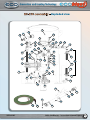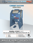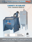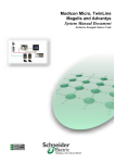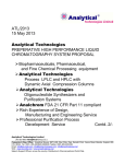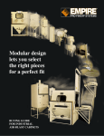
1
Innovation and Leading Technology
PORTABLE PRESSURE BLASTER
Models 346-646
With systems RC-176, RC-186 and Dual
( LG series )
INSTRUCTION MANUAL & PARTS
2013-04-03
346 & 646 Blasters - Instructions manual & parts
2013-04-03
1
Innovation and Leading Technology
Ta b l e o f c o n t e n t s
Page
Definition of Terms Used In This Manual.............................................................................................. 3
WARNINGS................................................................................................................................................................. 4
SETTING UP THE BLASTER..................................................................................................................................... 5
Control system RC 176..................................................................................................................................... 6
Control system RC 186..................................................................................................................................... 7
Dual control system RC176/RC186............................................................................................................ 8
Before you blast................................................................................................................................................. 9
Blasting................................................................................................................................................................. 10
Blasting (cont’d).............................................................................................................................................. 11
Maintenance schedule................................................................................................................................. 12
Maintenance Procedures............................................................................................................................ 13
Troubleshooting............................................................................................................................................. 14
Troubleshooting (cont’d).......................................................................................................................... 15
Troubleshooting (end)................................................................................................................................. 16
RC-176 assembly - Exploded view.................................................................................................................. 17
RC-176 assembly - Parts list.............................................................................................................................. 18
AV-176 Air valve assembly - Exploded view............................................................................................ 19
Abrasive metering valve MMV-175 - Exploded view............................................................................ 20
RC-186 assembly - Exploded view.................................................................................................................. 21
RC-186 assembly - Parts list.............................................................................................................................. 22
Air valve AV-186 - Exploded view................................................................................................................... 23
Abrasive metering valve PMV-186 - Exploded view............................................................................. 24
RC176/RC186 assembly - Exploded view...................................................................................................... 25
RC176/RC186 assembly - Parts list.................................................................................................................. 26
RC176 & RC186 - Electrical boxes, exploded view.......................................................................................... 27
RC176 & RC186 - Electrical boxes, Parts list.................................................................................................... 28
RC176 & RCzx186 assembly - Electrical boxes, exploded view............................................................. 29
Control handle systems - Exploded view.............................................................................................. 30
Control handle systems - Parts list.......................................................................................................... 31
NOVA 2000 assembly - Exploded view.......................................................................................................... 32
NOVA 2000 assembly - Parts list...................................................................................................................... 33
RADEX Breathing airline filter - Exploded view.................................................................................. 34
RADEX Breathing airline filter - Parts list.............................................................................................. 35
WARRANTY INFORMATION................................................................................................................................. 36
2013-04-03
346 & 646 Blasters - Instructions manual & parts
2
Innovation and Leading Technology
D e f i n i t i o n o f Te r m s U s e d I n T h i s M a n u a l
Abrasive (also known as “media”): granular material used for blasting a surface.
Blow down (also known as “depressurize”): to expulse air automatically or manually from a pressurized
vessel.
Control Handle: mandatory remote-control device used to start and stop the blaster.
Depressurize (also known as “blow down”): to expulse air automatically or manually from a pressurized
vessel.
Pressure Hold System (also known as “manual blow-down system”): blasting system in which the
pressure vessel stays pressurized when the control handle is released.
Pressure Release System (also known as “automatic blow-down system”: blasting system in which the
pressure vessel is automatically depressurized when the control handle is released.
Pressure Vessel: enclosed section of the blaster filled with pressurized air and abrasive during blasting
operations.
Pressurize: to fill the pressure vessel with compressed air.
Properly Trained Person: a person who has successfully passed a training course in sandblasting
pertaining mainly to the safe operation of stationary or portable Abrasive Blasters with capacities ranging
from 1.5 ft3 to 6.5 ft3 and who has read this entire manual and understands it
Silica : hazardous substance found in many naturally occurring abrasives.
NOTE: Abrasives containing silica must NEVER be used in any blasting situation. Even if respiratory protective
equipment is used, the resulting dust can cause respiratory disease
Safety Symbols
The safety symbols below are designed to ensure the safety and protection of the Abrasive Blaster
operator and of anyone else nearby. The explanations provided apply to sandblasting equipment.
WARNING :This symbol indicates a potentially
dangerous situation that could result in serious
injury or death if the instructions related to the
symbol are not carried out. Throughout the
manual, this warning triangle will appear to
denote instructions requiring special attention.
2013-04-03
DANGER : This symbol indicates a potentially
dangerous situation that WILL result in serious
injury or death if the instructions related to the
symbol are not carried out. Throughout the
manual, this warning triangle will appear to
denote instructions requiring special attention.
346 & 646 Blasters - Instructions manual & parts
3
Innovation and Leading Technology
Anyone who will be running the Abrasive Blaster or who will be nearby during its operation must
receive appropriate training in the safe operation of the equipment and must be cautioned
about the potential hazards. Besides being adequately trained, anyone who will be running the
Abrasive Blaster or who will be nearby during its operation must read, understand and follow
all the procedures explained in the user manual. For replacement manuals, please contact your
distributor or go to www.ECO.com.
Anyone who will be running the Abrasive Blaster or who will be nearby during its operation must
use respiratory protection that meets OSHA and NIOSH standards for breathing apparatus and
supplied air.
Because they contain large amounts of accumulated energy, Pressurized Vessels can cause serious
injury or death if safety procedures are ignored. Never perform maintenance on a pressurized
Pressure Vessel or attempt to open it under any circumstances. Always depressurize the equipment
and disconnect it properly from its air source before beginning maintenance. Never modify the
Pressure Vessel or do grinding or welding on it under any circumstances. Otherwise, the ASME
certification will be void. Damaged pressure vessels must NEVER be used.
The appropriate Remote (Deadman) Control System must be used to operate the Abrasive Blaster.
Abrasive Blasters must NEVER be used without Remote Controls. Bleeder-Type Control Handles
must NEVER be used with RC-176 or RC-186 Series Blasters because they can create dangerous
conditions where the blaster does not shut off when the handle is released.
Anyone who will be running the Abrasive Blaster or who will be nearby during its operation must
use the appropriate safety equipment as well as common sense to protect themselves. The required
safety equipment includes, but is not limited to, hearing, eye, body and lung protection. Because
of their weight, Abrasive Blasters and the objects being blasted can cause serious injury or death if
they topple over. All OSHA and NIOSH safety requirements must be followed at all times.
Only genuine ECO replacement parts must be used for maintenance on the Abrasive Blaster. The
equipment must NEVER be altered under any circumstances. Using altered brand parts can create
hazardous conditions and will void your warranty.
Before using the Abrasive Blaster, inspect it and make sure it is in good working order. Malfunctioning
or damaged equipment must NEVER be used.
Only clean, cool, dry compressed air must be supplied to the Abrasive Blaster. Hazardous conditions
can result if moisture or debris reaches the Remote Control System. Compressed air supplied to the
Blaster must not exceed 150 psi.
Using an air-line pressure regulator is strongly recommended.
Abrasive Blasters must NEVER be used in locations that could be deemed potentially hazardous
according to Article 500 of the National Electrical Code, NFPA 70. The Abrasive Blaster must NEVER
be used in wet locations. Electrically controlled Abrasive Blasters must always be connected to a
ground fault circuit interrupter (GFCI).
2013-04-03
346 & 646 Blasters - Instructions manual & parts
4
Innovation and Leading Technology
how to S E T U P T H E B L A S T E R
WARNING : The Operating Procedures described in this manual are intended to pr ovide basic
information about the safe operation of the features of ECO RC-176/RC-186 Series Abrasive
Blasters. The Abrasive Blaster should be operated only by persons who are fully trained in
abrasive blasting.
INSPECT THE PRESSURE VESSEL
PURGE THE AIR SUPPLY HOSE
When your Abrasive Blaster arrives, remove
the Handway Assembly and check if any
foreign objects have fallen in through the
pop-up opening. If so, remove them all, and
then reinstall the Handway Assembly.
Before the Air Supply Hose is connected to
the Abrasive Blaster, the hose must be purged
of any moisture or debris. If there is standing
water or moisture in the air line, the Abrasive
Blaster will not perform optimally. Air supplied
to the Abrasive Blaster must be cool, dry and
clean.
DANGER : Maintenance must NEVER be done
on the Abrasive Blaster nor should anyone try
to open it while it is pressurized. Otherwise,
serious injury or death will result from the
violent expulsion of compressed air and
propelled objects.
RE-TIGHTEN the HANDWAY ASSEMBLY
Once you have pressurized the Abrasive
Blaster for the first time, tighten the nut on
the Handway Assembly. Also, whenever
the Handway Assembly is removed for
maintenance, you must tighten the nut again,
prior to and following the next pressurization.
DANGER : Maintenance must NEVER be done
on the Abrasive Blaster nor should anyone try
to open it while it is pressurized. Serious injury
or death will result from the violent expulsion
of compressed air and propelled objects.
2013-04-03
ATTACH THE REMOTE CONTROL HANDLE
Using hose clamps or heavy wire ties, fasten
the Remote Control Handle to the Blast Hose
near the Nozzle. Next, form a loop of Twinline/
Control Cord where the first 6 inches of cord
curve away from the Blast Hose, then the next
6 inches run parallel to the Blast Hose, and then
the last 6 inches curve back to join the Blast
Hose. At the location where the loop ends,
fasten the Twinline/Control Cord to the Blast
Hose by wrapping duct tape twice around the
Twinline/Control Cord and then around the
Blast Hose to form a strain-relief attachment.
Do this only on the first connection near the
Control Handle. Fasten the rest of the Twinline/
Control Cord to the blast hose by wrapping
duct tape around the cord and the hose, every
3 feet, beginning at the Nozzle end of the Blast
Hose.
346 & 646 Blasters - Instructions manual & parts
5
Innovation and Leading Technology
R C 176 C o n t r o l s y s t e m
How it works
IMPORTANT :
A PRESSURE REGULATOR SHOULD BE INSTALLED ON THE AIRLINE FROM AIR COMPRESSOR
When the main air-line ball valve is ON, air is supplied to the AV-176 Combination Air Intake and Exhaust Valve,
which is usually closed.
When the Remote Control Handle on the dual air line is depressed, the AV-176 Combination Valve will be
activated, so the air can flow in. This forces the Plunger Pop-up Valve to seal the filling port and close the exhaust
section of the Combination Valve at the same time, thus pressurizing the Pressure Vessel.
When the Control Handle is released, blasting will stop and the Pressure Vessel will automatically depressurize.
When you have finished blasting, always be sure to close the main inlet air-line ball valve.
2013-04-03
346 & 646 Blasters - Instructions manual & parts
6
Innovation and Leading Technology
RC 186 Control system
How it works
AV186
6
IMPORTANT :
A PRESSURE REGULATOR SHOULD BE ON THE AIR LINE FROM THE AIR COMPRESSOR
Make sure the main air-line ball valve is turned on. The Vessel will be pressurized, so the air can flow to the AV186 Air Valve.
To begin blasting, depress the Remote Control Handle on the Blasting Hose near the Nozzle end. The Air Valve
and the PMV186 Abrasive Metering Valve will then open, and blasting will begin.
To stop blasting, release the Remote Control Handle. The Air Valve and the Abrasive Metering Valve will then
close to interrupt the blasting stream; however, the Pressure Vessel will stay pressurized.
When you have finished blasting or when you need to refill the Pressure Vessel with abrasive, depressurize the
Vessel. To do so, first make sure the Control Handle is released. Next, close the main inlet air-line ball valve, and
then slowly turn the manual depressurizing ball valve.
2013-04-03
346 & 646 Blasters - Instructions manual & parts
7
Innovation and Leading Technology
R C 176 / R C 1 8 6 D u a l c o n t r o l s y s t e m
How it works
AV186
6
The air line feeds air to an AV-176 Combination Air Intake and Exhaust Valve, which is usually closed.
Turning the Vessel Pressurizing Switch to ON activates the AV-176 Combination Valve. The Exhaust Valve part
of the valve seals the Vessel as air pushes the Plunger up to seal the filling port of the Vessel, which will then
become pressurized. Once pressurized, the Vessel is ready for blasting.
Before blasting begins, close all the doors in the blasting room equipped with a safety door switch.
Blasting can begin only once all the doors are closed. To begin, depress the Remote Control Handle on the
Blasting Hose near the Nozzle end. The Air Valve and the PMV-186 Abrasive Metering Valve will then open, and
blasting will begin.
When you release the Remote Control Handle, the blasting will STOP. The Pressure Vessel will stay pressurized,
ready to resume blasting when the Remote Control Handle is depressed again.
When you have finished blasting or when you need to refill the Pressure Vessel with abrasive, release the Remote
Control Handle. To depressurize the Pressure Vessel, switch the Vessel Depressurizing Switch to OFF.
WARNING : THE PRESSURE VESSEL MUST NEVER BE LEFT PRESSURIZED WHEN NOT IN USE.
The Pressure Vessel should be depressurized and the air-line supply turned OFF.
2013-04-03
346 & 646 Blasters - Instructions manual & parts
8
Innovation and Leading Technology
Before Blasting
PRE-BLASTing inspection
Before each use of the Abrasive Blaster, check and
make sure it is in safe working condition. Examine
the seals, hoses and other components closely for
wear or damage. Replace any damaged or worn
component before you begin blasting.
WARNING : An Abrasive Blaster must NEVER be
used if any of its components are damaged or
worn. Replace all damaged or worn parts before
using the equipment.
HOW TO ADD THE ABRASIVE
Before you fill the Abrasive Blaster, be sure that the
Inlet Valve is closed and that the Pressure Vessel is
depressurized. Pour the abrasive into the top of
the Abrasive Blaster. Allow it to flow around the
Pop-up and into the Pressure Vessel. Make sure
you neither overfill nor allow foreign materials
to enter. To prevent foreign items from getting
inside, the use of a screen is recommended.
DANGER : NEVER reach inside while the Abrasive
Blaster is being filled. The pop-up opening can
close unexpectedly and cause serious injury or
death.
WARNING : Abrasives containing silica must
NEVER be used with ECO Abrasive Blasters.
WARNING : The Inlet Valve must NEVER be open
while the Abrasive Blaster is being filled. Before
you begin filling, always be sure to close it.
WARNING : NEVER use electrically conductive
abrasives when the Abrasive Blaster is being used
with Electrical Remote Control Systems, unless
the sealed strain relief connectors have been
changed.
WARNING : An Abrasive Blaster containing
abrasive must NEVER be moved or transported.
2013-04-03
ABOUT THE REMOTE CONTROL SYSTEM
An electrical or pneumatic Remote Control System
(also referred to as “Deadman”) must always be used
with an Abrasive Blaster to start and stop blasting.
Electrical : On the Abrasive Blaster, the Remote
Control Handle must be connected to the female
twist-lock connector on the Abrasive Blaster. A 12
VDC power source (12-V battery or optional 120
VAC to 12 VDC converter) must be connected to the
male twist-lock connector.
Pneumatic : The Remote Control twin-line hose
must be connected to the Abrasive Blaster using
the threaded or quick-disconnect fittings that are
supplied. Using pneumatic Remote Control Systems
is not recommended with Blast Hoses exceeding
100 feet.
WARNING : The Abrasive Blaster must NEVER be
operated without a Remote Control System.
DANGER : Caution must always be used around
electrical sources to avoid electrical shock. Never
operate electrically remote-controlled Abrasive
Blasters in wet or other hazardous conditions.
HOW TO CONNECT HOSES
Before you connect hoses to the Abrasive Blaster,
be sure the Inlet Valve is closed and the compressed
air supply is off. Next, connect the hose from
the compressed air supply to the inlet on the
Abrasive Blaster and use safety clips to secure it.
Using an air-line pressure regulator is strongly
recommended. Connect the blast hose to the
coupling on the Metering Valve at the base of the
Abrasive Blaster. Use safety clips to secure it.
WARNING : Safety devices, such as clips and whip
checks (safety cables), must always be used to
secure the hose.
346 & 646 Blasters - Instructions manual & parts
9
Innovation and Leading Technology
Blasting
HOW TO PRESSURIZING THE ABRASIVE
BLASTER
Before you pressurize the Abrasive Blaster,
make sure that:
All “BEFORE BLASTING” procedures have been carried out.
The Inlet Valve is shut off.
The Blow-down Valve is shut off (RC-186 systems only).
The Remote Control Handle is released.
Each hose connection is secure and reinforced with a safety clip.
The Abrasive Blaster is set up in a safe
location, on level ground, and everyone
nearby has been informed of its presence.
Anyone who will be near the Abrasive Blaster
is wearing the required safety equipment.
The only persons who will be near the
Abrasive Blaster are those who have received
the proper training and who have read the
manual and understand it.
Once these conditions are met, you can turn
on the compressed air source and open the
Inlet Valve on the Abrasive Blaster. At that
point, the Abrasive Blaster will be ready for
blasting.
DANGER : Maintenance must NEVER be done on
the Abrasive Blaster nor should anyone try to open
it while it is pressurized. Otherwise, serious injury
or death will result from the violent expulsion of
compressed air and propelled objects.
The compressed air supplied to the Abrasive
Blaster should NEVER exceed 150 PSI (10.3 BAR).
WARNING : Activating the Remote Control
Handle can cause the Blast Hose to kick back.
Prepare by bracing yourself. Blasters with MMV175 Metering Valves usually kick back erratically
for a short while when they first start up.
WARNING : All persons who will be in the vicinity
of the blasting operation must be adequately
trained, must have read and understood the
manual and must be wearing the necessary safety
equipment.
2013-04-03
HOW TO USE THE ABRASIVE BLASTER
To prepare for blasting, pressurize the Abrasive
Blaster. To begin the flow of abrasive and compressed
air, push the safety flap down and squeeze the
Remote Control Handle. To adjust the air-abrasive
mixture, turn the handle on the Metering Valve. It will
take a bit of time for the adjusted mixture to reach the
Nozzle. The delay will vary according to the length of
the Blast Hose. Before you make adjustments, stop
the Abrasive Blaster by releasing the Remote Control
Handle. After a short period, which will again depend
on the length of the hose, the flow of compressed air
and abrasive will come to a halt. On Pressure Release
(RC-176) Abrasive Blasters, the Pressure Vessel
automatically exhausts through the Blow-Down
valve. This causes a burst of compressed air, which
can project loose objects, debris or abrasive toward
anyone in the area. Therefore, no one should be
close to a Pressure Release (RC-176) Abrasive Blaster
during blasting operations.
DANGER : Respiratory disease can result from
airborne particles generated by abrasive blasting.
Anyone involved in the blasting operation or in the
vicinity must wear the appropriate NIOSH/OSHAapproved breathing apparatus. Abrasives containing
silica must NEVER be used.
DANGER : Always stay clear of a Pressure Release (RC176) Abrasive Blaster while it is running. When the
Remote Control Handle is released, compressed air
will rush out suddenly and violently from the exhaust
valve. You must wait until the Abrasive Blaster is
depressurized before adjusting the Metering Valve.
WARNING : Only persons who have been fully
trained in abrasive blasting should run the Abrasive
Blaster. This manual provides only basic information
on the safe operation of the features of ECO RC-176/
RC-186 Series Abrasive Blasters..
WARNING : You must NEVER point the Blast Nozzle
towards anyone, including yourself, or towards the
Abrasive Blaster.
WARNING : Make sure the Choke Valve is completely
open during blasting to prevent damage to the
equipment.
346 & 646 Blasters - Instructions manual & parts
10
Innovation and Leading Technology
Blasting (end)
HOW TO DRAIN THE MOISTURE SEPARATOR
The Moisture Separator must be drained
periodically during blasting. To do so, it is best to
keep the Drain Valve slightly open. This way, air
will continuously escape and force the moisture
out.
WARNING : The Abrasive Blaster must receive
clean, cool, dry compressed air to run properly.
Depending on the quality of the air being
supplied, the Moisture Separator included with
the Abrasive Blaster may not have the capacity to
ensure this is the case.
HOW TO SHUT DOWN THE ABRASIVE BLASTER
When you have finished blasting, you must shut
down the Abrasive Blaster. To do so, release the
Remote Control Handle and then shut off the Inlet
Valve. In the case of an RC-176 Pressure Release,
the Abrasive Blaster will be depressurized by that
time.
HOW TO DISCONNECT THE AIR SUPPLY HOSE
Even once you have depressurized the Abrasive
Blaster and shut off the Inlet Valve, the Compressed
Air Supply Hose may still contain pressure, which
must be expelled before you disconnect the hose. To
do so, shut off the compressed air at its source and
open the Drain Valve on the Abrasive Blaster. Slowly
open the Inlet Valve on the Abrasive Blaster. This will
allow the compressed air stored in the Compressed
Air Supply Hose to exit through the Drain Valve. Once
the sound of air escaping through the Drain Valve
has stopped, squeeze the Compressed Air Supply
Hose and make sure there is no more compressed air
left inside. Once this is done, you can disconnect it.
DANGER : Compressed Air Supply Hoses must NEVER
be disconnected until the “HOW TO DISCONNECT
THE AIR SUPPLY HOSE” procedures have been carried
out. Otherwise, the hose could blow off violently and
injure or kill someone in the area.
When using an RC-186 Pressure Hold, make sure
that the pneumatic Control Handle is released.
Next, shut off the Main Air Supply Valve and
slowly open the Blow-Down Valve to let out the
compressed air that is stored in the Abrasive
Blaster.
AV186
RC-176 Pressure Release System
2013-04-03
RC-186 Pressure Hold System
346 & 646 Blasters - Instructions manual & parts
11
Innovation and Leading Technology
Maintenance Schedule
WARNING : Only experienced, qualified persons should perform maintenance. The
maintenance procedures and timetable below must be followed; otherwise, the equipment
may perform poorly or fail. Furthermore, the equipment warranty will become void.
DANGER : Maintenance must NEVER be done on the Abrasive Blaster nor should anyone
try to open it while it is pressurized. Serious injury or death will result from the violent
expulsion of compressed air and propelled objects.
Inspections and Maintenance
Frequency
1- Inspect personal protective equipment
Every day
2- Inspect remote control handles and control hose/cord
Every Day
3- Inspect blast hose, couplings & gaskets
Every Day
4- Inspect blasting nozzle
Every Day
5- Inspect air hose, couplings and gasket
Every Day
6- Inspect & clean blow-down muffler (if equipped)
Every Week
7- Inspect pop-up & pop-up gasket
Every Months
8- Service metering valve
Every 3 Months
9- Service combination valve (if equipped)
Every 3 Months
10- Service control valve(s) (if equipped)
Every 3 Months
2013-04-03
346 & 646 Blasters - Instructions manual & parts
12
Innovation and Leading Technology
Maintenance Procedures
1. Inspect Personal Protective Equipment (PPE)
Inspect all PPE to make sure that it fits and that it is in good working condition. Replace or repair PPE, or have it fitted, as needed.
2. Inspect Remote Control Handles and Control Hose/Cord
Pneumatic Remote Control Systems :
Inspect the Control Handle to be sure the Safety Flap/Lever Lock/Button is in good working condition. Check for damages, and replace or repair components as needed. Inspect the twin-line hoses and replace them if there are leaks, abrasions or soft spots.
Electric Remote Control Systems :
Inspect the Control Handle and make sure the Safety Flap/Lever Lock/Button is in good working condition. Check
for damages, and replace or repair components as needed. Inspect the control cord and replace it if there are
damaged plug ends or signs of abrasion, exposed wires or cracks
3. Inspect Blast Hose, Couplings & Gaskets
Check the Blast Hose for leaks, abrasions and soft spots. Inspect the couplings for damage, leaks and wear. Check
the coupling gaskets for leaks and wear. Replace all components as needed. Be sure safety clips and whip checks
(safety cables) are used to secure Blast Hose connections.
4. Inspect Blasting Nozzle
Check the Blasting Nozzle for wear, and measure the bore diameter. If the bore diameter is worn to the point of
being 1/16 in. larger than its original diameter, replace the Blasting Nozzle. For instance, a #5 Nozzle (5/16 in. bore)
needs to be replaced when the bore reaches 3/8 in.
5. Inspect Air Hose, Couplings & Gaskets
Check the Air Hose for leaks, abrasions and soft spots. Check the couplings for damage, leaks and wear. Check
the coupling gaskets for leaks and wear. Replace all components as needed. Be sure safety clips and whip checks
(safety cables) are used to secure Air Hose connections.
6. Inspect & Clean Blow-down Muffler
Remove the Blow-Down Muffler and turn it upside down. Tap it on a hard surface to free any debris that may be
trapped inside. Replace the muffler if it is blocked and the obstruction cannot be cleared
7. Inspect Blow-down Hose Assembly
Remove and inspect the Blow-Down Hose Assembly. Replace it if you find leaks or soft spots.
8. Inspect Pop-Up & Pop-Up Gasket
Check the Pop-up and Pop-up Gasket for wear. Replace as needed
9. Service Metering Valve
Disassemble and clean the Metering Valve. Check for worn components and make sure it is working properly.
Replace any worn components. Lubricate the MMV-175 and PMV-186 valves with an anti-seize compound before
reassembly.
10. Service Air Valve AV-186
Disassemble and clean the valve. Check for worn components and make sure it is working properly. Replace any worn components. Lubricate with an anti-seize compound before reassembly.
11. Service Combination Valve AV-176
Disassemble and clean the valve. Check for worn components and make sure it is working properly. Replace any worn components. Lubricate with an anti-seize compound before reassembly.
12. Service Control Valve(s)
Disassemble and clean the valve(s). Check for worn components and make sure everything is working properly. Replace any worn components. Lubricate with an anti-seize compound before reassembly
2013-04-03
346 & 646 Blasters - Instructions manual & parts
13
Innovation and Leading Technology
Tr o u b l e s h o o t i n g
DANGER : The Abrasive Blaster must NEVER be opened while it is pressurized. Extreme
caution is required when troubleshooting involves pressurizing the Abrasive Blaster.
Only experienced, qualified persons should perform troubleshooting procedures.
ABRASIVE NOT FLOWING DURING BLASTING (AIR
ONLY)
Possible Causes :
1. The Abrasive Blaster is empty. The abrasive cut-off function (if equipped) is engaged
and is preventing the abrasive from flowing.
2. The Metering Valve is closed or not properly adjusted.
If you suspect that a PMV-186 Metering Valve is not
opening, conduct the following test : Shut off the Metering Valve completely by turning the knob clockwise
until it stops. Next, turn it counterclockwise about 9
full turns. Then, depress the Control Handle and check
if the knob is difficult to turn or does not turn at all If so,
the Metering Valve is opening properly.
3. There is a blockage in the Metering Valve.
To free the blockage from a PMV-186 Metering
Valve, begin by turning the knob on the Metering
Valve clockwise until it stops. Then, turn the knob
counterclockwise 9 full turns so it is fully open. Depress
the Control Handle and have a second qualified person
close the choke valve for 2 seconds and then re-open
it immediately. Minor obstructions, such as paint chips,
a bit of wet abrasive or a piece of paper, will be forced
through the Metering Valve and out the Nozzle. Turn
the Metering Valve back to the required blast setting
and check if the obstruction has been removed.
If there is still a blockage, depressurize the Abrasive
Blaster, remove the Pusher Line and the Metering Valve
and check if there is a steady stream of abrasive. If so,
allow the Abrasive Blaster to empty, and then reinstall the
Metering Valve.
It is advisable to use a screen to keep foreign objects
from getting inside the Abrasive Blaster and causing
a blockage.
4. There is wet abrasive in the Abrasive Blaster.
The wet abrasive must be removed. To do so,
depressurize the Abrasive Blaster, remove the Handway
Assembly and scoop or vacuum out the wet abrasive.
The Abrasive Blaster must always be used with dry
abrasive and supplied with clean, cool, dry air to keep
the abrasive dry. For outdoor operations, using a lid
is recommended to prevent water from getting inside
the Abrasive Blaster.
ABRASIVE STREAM TOO HEAVY OR THROBBING
during BLASTING
Possible Causes :
Note : When RC-176 systems first start up, they may throb
for a while if there is an accumulation of abrasive in the
blast hose from a previous operation. This is normal, and
no corrective action is needed.
1. The Choke Valve is partially closed.
The Abrasive Blaster should be operated ONLY with the
Choke Valve fully open. Doing otherwise will cause
2. The Metering Valve needs adjusting.
Refer to the instructions on page 10 on how to adjust
Metering Valves.
If you find a large obstruction, you will have to remove it
from inside the Pressure Vessel. To do so, start by making
sure that the Abrasive Blaster is depressurized. Next,
remove the Handway Assembly, scoop or vacuum all the
abrasive out of the Pressure Vessel, and then remove the
obstruction. You can then reinstall the Handway Assembly
and the Metering Valve. Be sure to tighten them securely.
Once this is done, you can refill the Abrasive Blaster.
2013-04-03
346 & 646 Blasters - Instructions manual & parts
14
Innovation and Leading Technology
Tr o u b l e s h o o t i n g ( c o n t ’ d )
DANGER : The Abrasive Blaster must NEVER be opened while it is pressurized. Extreme
caution is required when troubleshooting involves pressurizing the Abrasive Blaster.
Only experienced, qualified persons should perform troubleshooting procedures.
LOW PRESSURE AT THE NOZZLE
Possible Causes :
ABRASIVE BLASTER DOES NOT TURN ON OR IS SLOW
TO DO SO
Possible Causes :
1. The air compressor is too small or the load
button is not activated.
2. The Nozzle is worn out, creating too much
demand for the compressor.
3. The hose supplying air to the blaster is too small.
4. There is a hole in the blast hose.
5. The pop-up is not sealing properly.
6. There are one or more leaks in the Handway
Assembly.
7. The Inlet Air Valve is dirty or blocked.
8. The lower plunger (if equipped) in the Inlet Air
Valve is damaged, faulty or worn out.
9. The Choke Valve is partially closed. The Abrasive
Blaster should be operated ONLY with the Choke
Valve fully open. Doing otherwise will cause
damage to the Abrasive Blaster.
10.The Abrasive Metering Valve is open too far.
11.The Nozzle is blocked.
12.The Regulator (if equipped) needs adjusting.
2013-04-03
1. The air compressor is too small or the load button
is not activated.
2. The Nozzle is worn out, creating too much
demand for the compressor.
3. The hose supplying air to the blaster is too small.
4. There are one or more leaks in the control hoses
and/or fittings.
5. The Nozzle is blocked.
6. The Inlet Air Valve is dirty or blocked.
7. The Pneumatic Control Handle (if equipped) is
faulty, damaged or worn out.
8. The Electrical Control Handle (if equipped) is
faulty, damaged or worn out.
9. The Electrical Control coil or coils (if equipped)
are faulty.
10.The Power Source (battery or AC-DC converter)
is not generating enough power to open the
electrical control valves (if equipped).
11.The Control Valve (if equipped) needs servicing
due to insufficient lubrication, or it is jammed,
faulty, damaged or worn out.
346 & 646 Blasters - Instructions manual & parts
15
Innovation and Leading Technology
Tr o u b l e s h o o t i n g ( e n d )
DANGER : The Abrasive Blaster must NEVER be opened while it is pressurized. Extreme
caution is required when troubleshooting involves pressurizing the Abrasive Blaster.
Only experienced, qualified persons should perform troubleshooting procedures.
BLAST MACHINE TURNS ON ACCIDENTALLY OR
unexpectedly
Possible Causes :
1. The safety flap, lever or lock button on the Control
Handle is damaged or missing.
2. The Pneumatic Control Handle (if equipped) is
faulty, damaged or worn out.
3. The Electrical Control Handle (if equipped) is
faulty, damaged or worn out.
4. The Electrical Control Cord (if equipped) is faulty,
damaged or worn out (if equipped).
BLAST MACHINE TURNS OFF TOO SLOWLY OR
DOES NOT TURN OFF WHEN CONTROL HANDLE IS
RELEASED
Possible Causes :
1. The Pneumatic Control Handle (if equipped) is
faulty, damaged or worn out
2. .The Electrical Control Handle (if equipped) is
faulty, damaged or worn out.
3. The Electrical Control Cord (if equipped) is faulty,
damaged or worn out.
4. The Air Valve (if equipped) needs servicing due
to insufficient lubrication, or it is jammed, faulty,
damaged or worn out.
5. The Combination Valve Assembly (if equipped) is
not seating properly because it is faulty, damaged
or worn out.
6. An obstruction in the Blow-Down Muffler is
hindering the release of air. .
2013-04-03
AIR BLAST STOPS BUT ABRASIVE CONTINUES TO
FLOW WHEN CONTROL HANDLE IS RELEASED
(APPLIES ONLY TO SYSTEMS WITH PMV-186 SERIES
METERING VALVES)
Possible Causes :
1. The Urethane Seat (black) in the Metering Valve is
faulty, damaged or worn out.
2. The MN2 Sleeve in the Metering Valve is faulty,
damaged or worn out.
3. The MN2 Plunger in the Metering Valve is faulty,
damaged or worn out.
4. Foreign material is jammed between the Plunger
and the Metering Valve Seat.
5. The Metering Valve Spring is faulty, damaged or
worn out.
ABRASIVE STOPS FLOWING BUT AIR BLAST
CONTINUES WHEN CONTROL HANDLE IS RELEASED
Possible Causes :
1. The lower plunger in the AV-176 or AV-186 Air Valve
is faulty, damaged or worn out.
2. The piston seal in the AV-176 or AV-186 is faulty,
damaged or worn out.
3. The O-ring in the AV-176 or AV-186 Valve is faulty,
damaged or worn out.
346 & 646 Blasters - Instructions manual & parts
16
Innovation and Leading Technology
R C - 176 a s s e m b l y - Exploded view
10
30
1
29
12
7
2
29
30 15
8
3
19
31
18
21
28A
10
22
17
32
14
15
15
20
11
23
16
28B
15
29
28
26
5
28C
15
21
25
13
23
15
28B
4
28A
9
27
21
24
6
43
39
38
41
42
2013-04-03
43
40
36
37
346 & 646 Blasters - Instructions manual & parts
17
Innovation and Leading Technology
R C - 176 a s s e m b l y - Parts list
#
STOCK
PRESSURE VESSEL ONLY (346)
26
630890
UNION PA 1¼’’
723000
PRESSURE VESSEL ONLY (646)
27
608230
DRAIN COCK VALVE
610056
740102
618241
740101
ACcESS DOOR KIT
ACcESS DOOR KIT (LG serie)
ACcESS DOOR gasket
ACcESS DOOR gasket (LG serie)
28
28A
28B
28C
770100
607087
607088
770101
PUSH LINE HOSE ASS’y (28A-b-c)
HOSE INSERT SWIVEL 1¼’’
DOUBLE BOLT CLAMP
PUSH LINE HOSE 30’’ X 1¼’’
4
740001
740002
AXle (model 346)
AXle (model 646)
29
630805
NIPPLE 3’’ X 1¼’’
5
608821
6
770070
AIR valve av-176 *
30
31
32
630840
630864
632214
776100
‘’T’’ 1¼’’ X 1¼’’
1¼’’ X ¼’’ COUPLING
REDUCER NIPPLE ¼’’ X 1/8’’
#
1
2
3
STOCK
DESCRIPTION
713000
9
10
11
12
13
740004
740100
740104
740007
610044
611053
630884
607051
611022
740006
MMV-175 VALVE assembly * *
‘‘O’’ ring
‘‘O’’ ring (LG serie)
‘‘O’’ ring FOR 10 pi3 (LG serie)
5’’ plunger
5’’ plunger (LG serie)
1¼’’ moisture separator
1¼’’ plug
NH-¾’’ ALUM. NOZZLE HOLDER
¼’’ NTP gauge
Wheel
14
606003
hose ¾’’ sbh
15
630801
1¼’’ nipple CLOSE
16
630111
NIPPLE 6’’ X ¼’’
17
18
19
20
630838
632214
611035
632232
CROSS 1¼’’
HEX NIPPLE ¼’’ x 1/8’’
AIR LINE FILTER
¼’’ BRASS STREET ELBOW
21
630851
1¼’’ x 90° elbow mF
22
632026
1/8’’ BRASS STREET ELBOW
23
24
25
608105
607074
631151
1¼’’ ball valve
7
8
607001
50’ X 1’’ hose ass’y c/w fitting QCN-NHN
50’ x 1’’ hose ass’y w/O fitting
346
50 ‘ hose EXTENSION c/w fitting QCN-qcn
50’ X 1¼’’ hose ass’y c/w fitting QCN-NHN
mOD.
50’ 1¼’’hose ass’y w/O fitting
646
50 ‘ hose EXTENSION c/w fitting QCN-qcn
qcn - 1’’ qUICK sNAP fITTING (346)
607011
qcn - 1¼’’ qUICK sNAP fITTING (646)
607018
607019
nhn - 1’’ NOZZLE COUPLING (346)
nhn - 1¼’’ NOZZLE COUPLING (646)
DVC-4 STD. TUNGST. VENTURI NOZZLE
MODEL 346
DVC-5 STD. TUNGST. VENTURI NOZZLE
MODEL 646
nw-1 NOZZLE WASHER
qcn-o qUICK sNAP fITTING WASHER
DUAL LINE REMOTE CONTROL HOSE 55’
C/W FITTING
PNEUMATIC DEADMAN CONTROL HANDLE
776101
36
776102
776125
776127
776128
37
38
605204
39
605205
41
618016
618005
42
606193
43
908006
40
DESCRIPTION
mOD.
***
tank coupling 1¼’’ nylon
2’’ x 1¼’’ REDUCER
details parts page 19
* See
See
parts page 20
* * See details
details
parts page 30
* * *
2013-04-03
346 & 646 Blasters - Instructions manual & parts
18
Innovation and Leading Technology
AV - 176 A i r v a l v e a s s e m b l y - Exploded view
A
32
30
31
14
15
21
20
13
22
11
10
33
9
12
8
34
7
6
19
18
26
28
23
5
17
27
29
3
2
4
1
16
A
#
608821
STOCK CODE
av-176 complete valve ass’Y
DESCRIPTION
#
STOCK CODE
DESCRIPTION
10
11
12
VALVE PLUG
O-RING
BASE
O-RING
1
770181
2
770191
PIN
17
3
770186
PINCH RAM
18
4
770184
UPPER ROD ASS’Y , include : ITEMS 26, 27, 28, 29
19
5
770192
CYLINDER
21
6
770187
SPRING
22
CURVED SPRING WASHER
CAP
SEAL KIT
770182
EXTERNAL CIRCLIP
PISTON SEAL (770190)
LOCK NUT
7
770188
SHAFT
28
UPPER ROD SEAL
8
770189
PISTON
29
CIRCLIP
9
770185
LOWER ROD ASS’Y , nclude : ITEMS 30, 31, 32, 33
32
13
770196
BASE
26
770219
UPPER ROD GUIDE
LOWER ROD SEAL
14
770197
HEX HEAD BOLT
27
770220
UPPER ROD GUIDE BUSH
15
770198
FLAT WASHER
30
770223
LOWER ROD GUIDE
16
770199
NUT
31
770224
LOWER ROD GUIDE BUSH
20
770213
FLAT WASHER
32
770225
LOWER ROD SEAL
23
770216
EXHAUST FILTER
33
770226
CIRCLIP
(34)
PLUG KIT
770183
2013-04-03
include : ITEMS 11,12, 20, 21, 22
346 & 646 Blasters - Instructions manual & parts
19
Innovation and Leading Technology
Abrasive metering valve MMV-175 - Exploded view
B
2
1
3
4
5
6
7
8
9
10
#
STOCK
DESCRIPTION
1
2
3
4
5
770069
770079
770078
770077
770073
knob
roll pin
bolt c/w washer
cap
plunger
B
770070
2013-04-03
#
STOCK
6
7
8
9
10
770076
770072
770074
770075
770071
DESCRIPTION
body
seal
urethane sleeve
gasket
pipe nipple 1¼’’ fEM. x 1¼’’ mal.
MMv-175 COMPLETE AIR VALVE ASSEMBLY
346 & 646 Blasters - Instructions manual & parts
20
Innovation and Leading Technology
R C - 1 8 6 a s s e m b l y - Exploded view
10
14
20
1
7
17
8
15
20
22
23
16
15
11
26
10
2
3
31 29
9
16
18
13
31
12
15
5
21
22
14
15
19
27
25
28
22
24A
24B
4
24 24C
24B
43
24A
6
30
39
21
38
41
42
2013-04-03
43
40
36
37
346 & 646 Blasters - Instructions manual & parts
21
Innovation and Leading Technology
R C - 1 8 6 a s s e m b l y - Parts list
#
STOCK
STOCK
DESCRIPTION DESCRIPTION
1
713000
713000
723000
723000
2
2
3
610056
610056
618241
740102
PRESSUREVESSEL
VESSELONLY
ONLY(346)
( MOD. 346 ) 24 770100
PRESSURE
PRESSUREVESSEL
VESSELONLY
ONLY(646)
( MOD. 646 ) 24A 607087
PRESSURE
24B 607088
ACcESSDOOR
DOORKIT
KIT
ACcESS
24C 770101
DOOR DOOR
GASKET
ACcESS
KIT (LG serie)
4
3
740001
618241
740002
740101
5
4
6
608822
740001
5
7
608822
740004
8
6
9
10
7
740007
608845
611053
740004
11
740104
630864
740007
611022
610044
740006
12
8
13
9
14
10
15
11
16
12
17
13
18
14
19
15
20
16
21
17
22
18
23
19
20
21
740002
608845
630840
740100
611053
630884
630840
630801
630864
632202
611022
632226
740006
324570
630884
324571
630801
630805
AXel (FOR
MODEL
346)
ACcESS
DOOR
gasket
AXel (FOR
MODEL
646)(LG serie)
ACcESS
DOOR
gasket
av-186
AIR valve
AXle
(model
346) *
AXle
(model
646)
PMV-186
VALVE
assembly * *
‘‘O’’valve
ring av-186 *
AIR
5’’ plunger
PMV-186
VALVE assembly * *
1¼’’
moisture separator
ring
‘‘O’’
1¼’’
‘‘t’’ coupling
‘‘O’’
ring
(LG serie)
‘‘O’’
10 pi3 (LG serie)
ring
1¼‘‘
x ¼’’FOR
coupling
plunger
5’’¼’’
NTP gauge
5’’WHEEL
plunger (LG serie)
1¼’’
moisture
separator
1¼‘‘
PLUG
1¼’’
coupling
1¼‘‘‘‘t’’
nipple
1¼‘‘
x ¼’’ couplin
nipple
¼’’
¼’’STREET
NTP gauge
‘‘T’’ ¼’’
Wheel
PUSH IN FITTING 1/8’’
1¼‘‘
PLUG
BLUE
TUBING AIR LINE
630851
1¼’’
nipple
nipple
3’’ CLOSE
x 1¼’’
NIPPLE
¼’’
1¼’’ x 90° elbow mf
STREET
‘‘T’’ valve
¼’’
1¼’’ ball
PUSH
IN FITTING
AIR LINE
FILTER 1/8’’
BLUE TUBING AIR LINE
nipple 3’’ x 1¼’’
1¼’’ x 90° elbow mF
22
608105
1¼’’ ball valve
23
611035
AIR LINE FILTER
632202
630851
632226
608105
324570
611035
324571
630805
#
STOCK
DESCRIPTION
push line assembly (24A-b-c)
HOSE INSERT SWIVEL 1¼’’
DOUBLE BOLT CLAMP
PUSH LINE HOSE 30’’ X 1¼’’
25
770180
2’’ x 1¼’’ REDUCER bst
26
630838
1¼’’ coupling cross
27
608230
drain cock valve
28
630801
1¼’’ NIPPLE CLOSE
29
632018
TEE 1/8’’
30
607074
632214
776100
TANK COUPLING 1¼’’ nylon
31
REDUCER NIPPLE ¼’’ X 1/8’’
42
607001
607011
607018
607019
605204
605205
618016
618005
606193
50’ X 1’’ hose ass’y c/w fitting QCN-NHN
50’ x 1’’ hose ass’y w/O fitting
346
50 ‘ hose EXTENSION c/w fitting QCN-NHN
50’ X 1¼’’ hose ass’y c/w fitting QCN-NHN
mOD.
50’ 1¼’’hose ass’y w/O fitting
646
50 ‘ hose EXTENSION c/w fitting QCN-NHN
qcn - 1’’ qUICK sNAP fITTING (346)
qcn - 1¼’’ qUICK sNAP fITTING (646)
nhn - 1’’ NOZZLE COUPLING
(346)
nhn - 1¼’’ NOZZLE COUPLING (646)
DVC-4 STD. TUNGST. VENTURI NOZZLE MODEL 346
DVC-5 STD. TUNGST. VENTURI NOZZLE MODEL 646
nw-1 NOZZLE WASHER
qcn-o qUICK sNAP fITTING WASHER
DUAL LINE REMOTE CONTROL HOSE 55’ C/W FITTING
43
908006
PNEUMATIC DEADMAN CONTROL HANDLE * * *
776101
36
776102
776125
776127
776128
37
38
39
40
41
mOD.
details parts page 23
* See
See
parts page 24
* * See details
details
parts page 30
* * *
2013-04-03
346 & 646 Blasters - Instructions manual & parts
22
Innovation and Leading Technology
A i r v a l v e AV - 1 8 6 - Exploded view
B
1
2
22
23
5
4
7
8
9
3
11
6
13
14
10
16
18
19
12
15
17
20
B
608822
#
STOCK CODE
1
2
4
5
*
*
*
6
7
*
8
9
10
*
*
11
12
*
13
14
2013-04-03
aIR VALVE av-186 : complete valve ass’Y
DESCRIPTION
QTY
*
#
1
15
O-RING 31.5mm x 2mm
1
16
COVER
1
17
LOCK NUT 5/16’’ UNF
1
18
FLAT WASHER 8mm
2
FLAT WASHER
CAP
3
21
STOCK CODE
*
DESCRIPTION
QTY
RETAINER
1
LOCK NUT 1/4’’ UNF
1
INNER BUSH
1
O-RING 34mm x 1.8mm
1
19
BODY
1
20
SPRING WASHER 1/4’’
4
2
21
NUT 1/4’’ unc
4
DIAPHRAGM
1
22
hex head machine screw ¼’’ unc x 35mm
4
GUIDE BUSH
1
23
spring
1
O-RING 45mm x 3mm
1
O-RING 9mm x 2.65mm
1
SHAFT
1
FLAT WASHER
1
SEAT HOLDER
1
RUBBER GASKET
1
*
* Service kit available only :
608823 = # 2, 4, 5, 7, 9, 10, 12, 14,16, 18.
346 & 646 Blasters - Instructions manual & parts
23
Innovation and Leading Technology
Abrasive metering valve PMV-186 - Exploded view
B
21
1
2
23
3
6
8
4
5
10
7
9
13
14
11
12
15
17
25
18
19
20
16
22
24
A
608845
#
STOCK CODE
PMV-186 complete valve ass’Y
#
DESCRIPTION
STOCK CODE
DESCRIPTION
1
770022
top
15
608840
URETHANE SEAT
2
770201
anti-vibration washer
16
608841
SEAT HOLDER
3
770023
STOP RING
17
608839
O-RING
4
Spring
18
770032
BASE
PISTON SEAL
19
FLAT WASHER
PLUNGER COVER
770207
7
770024
770213
770202
770203
20
HEX HEAD BOLT
NYLON WASHER
770033
770213
21
770208
EXHAUST FILTER
8
PISTON
22
770209
SQUARE HEAD PLUG
9
770204
770121
TUNGSTENE PLUNGER
23
770021
CONTROL KNOB
10
CYLINDER
24
1 ¼’’ X 1 ¼’’ PIPE NIPPLE
11
608830
770034
PLUNGER SEAL c/wITH o-ring
25
TUNGSTEN SEAT KIT INCLUDE : #15, 16, 17
12
770030
770211
PLUNGER SEAL c/without o-ring
13
770206
BUSH
14
608832
TUNGSTEN CARBIDE SLEEVE
5
6
2013-04-03
26
KIT
770210
INCLUDE ITEMS # 5,11,12, 13, 14, and 15, 16, 17
346 & 646 Blasters - Instructions manual & parts
24
Innovation and Leading Technology
R C 176 / R C 1 8 6 a s s e m b l y - Exploded view
A
See details
page 29
1
26
12
7
10
20
20
20
8
2 3
11
14
31
33
22 16
21
32
18
26
5
15
24
15
10
19
24
18 20
17
19
29
23
30
15
28A
21
15
28B
28C
25
13
28A
4
27
6
44
42
2013-04-03
B
See details
page 29
21
43
38
43
28
28B
9
23
18
40
39
36
41
37
346 & 646 Blasters - Instructions manual & parts
25
Innovation and Leading Technology
R C 176 / R C 1 8 6 a s s e m b l y - Parts list
##
#
STOCK
PRESSURE
PRESSUREVESSEL
VESSELONLY
ONLY(346)
(346)
27
608230
723000
723000
PRESSURE
PRESSUREVESSEL
VESSELONLY
ONLY(646)
(646)
28
770100
drain COCK VALVE
PUSH LINE HOSE ASS’Y (28-a-b-c)
610056
610056
ACcESS
ACcESSDOOR
DOORKIT
KIT
28A
607087
SWIVEL HOSE INSERT 1¼‘‘
618241
740102
ACcESSDOOR
DOORKIT
gasket
ACcESS
(LG serie)
28B
607088
DOUBLE BOLT CLAMP
740001
618241
740101
740002
AXle (model
346)
ACcESS
DOOR gasket
ACcESS
DOOR gasket
(LG serie)
AXle (model
646)
28C
770101
29
630838
5
4
6
608822
740001
AXle
(model
346) 1¼’’ *
AV-186
AIR valve
30
608821
608845
740002
AXle
(model
646)
PMV-186
VALVE
assembly * *
31
630864
PUSH LINE HOSE 30’’ x 1¼‘‘
1¼’’ coupling cross
aV 176 VALVE ASS’Y * * *
1 ¼’’ X ¼’’ coupling
57
618201
608822
AIR
‘‘O’’valve
ring av-186 *
32
611035
68
610041
608845
PMV-186
VALVE assembly * *
5’’ plunger
33
632232
9
740004
611053
‘‘O’’
1¼’’ring
moisture separator
36
776100
710
740100
630884
‘‘O’’
1¼’’ring
plug(LG serie)
11
740104
607051
‘‘O’’
FOR 10
pi (LG serie)
ring
NH-¾’’
ALUM.
NOZZLE
HOLDER
12
8
13
740007
611122
5’’
¼’’plunger
NTP gauge
610044
740006
5’’
plunger (LG serie)
Wheel
914
606003
611053
1¼’’
moisture
hose
¾’’ sbh separator
15
10
16
11
17
12
13
18
14
19
630801 1¼’’
1¼’’
nipple CLOSE
630884
plug
630111 NH-¾’’
NIPPLE
6’’ XNOZZLE
¼’’
607051
ALUM.
HOLDER
324570 ¼’’
push
1/8’’
611022
NTPin
gauge
740006
632214 Wheel
aDAPTOR 1/4’’ TO 1/8’’
606003
¾’’ sbh
632018 hose
TEE 1/8’’
ff
15
20
630801
630805
21
16
630851 NIPPLE
630111
X ¼’’
1¼’’ x6’’
90°
ELBOW
40
22
17
18
23
632026 push
324570
in 1/8’’
STREET
ELBOW 1/8’’
632214
1/4’’
TO 1/8’’
608105 aDAPTOR
1¼’’ ball
valve
41
24
19
632002 TEE
632018
1/8’’NIPPLE
ff
HEX.
1/8’’
43
25
20
770180
630805
2’’ x 1¼’’3’’REDUCER
nipple
x 1¼’’ bst
21
26
630851
630840
1¼’’
90° elbow mF
TEEx1¼’’
22
632026
STREET ELBOW 1/8’’
23
24
25
26
608105
632002
770180
630840
1¼’’ ball valve
HEX. NIPPLE 1/8’’
2’’ x 1¼’’ REDUCER bst
TEE 1¼’’
11
2
2
3
34
STOCK
STOCK
DESCRIPTION
DESCRIPTION
713000
713000
3
1¼’’
CLOSE
1¼’’nipple
x 3’’ NIPPLE
37
38
39
42
44
776101
776102
776125
776127
776128
607001
607011
607018
607019
605204
605205
618016
618005
606193
908006
607074
DESCRIPTION
AIR LINE FILTER
ELBOW ¼’’ x 90° MF
mOD.
346
mOD.
646
50’ X 1’’ hose ass’y c/w fitting QCN-NHN
50’ x 1’’ hose ass’y w/O fitting
50 ‘ hose EXTENSION c/w fitting QCN-QCN
50’ X 1¼’’ hose ass’y c/w fitting QCN-NHN
50’ 1¼’’hose ass’y w/O fitting
50 ‘ hose EXTENSION c/w fitting QCN-QCN
qcn - 1’’ qUICK sNAP fITTING (346)
qcn - 1¼’’ qUICK sNAP fITTING (646)
nhn - 1’’ NOZZLE COUPLING
(346)
nhn - 1¼’’ NOZZLE COUPLING (646)
DVC-4 STD. TUNGST. VENTURI NOZZLE MODEL 346
DVC-5 STD. TUNGST. VENTURI NOZZLE MODEL 646
nw-1 NOZZLE WASHER
qcn-o qUICK sNAP fITTING WASHER
DUAL LINE REMOTE CONTROL HOSE 55’ C/W FITTING
PNEUMATIC DEADMAN CONTROL HANDLE * * * *
tank coupling 1¼’’ nylon
See details parts page 19
*
See details parts page 24
** See details parts page 23
*** See details parts page 30
****
2013-04-03
346 & 646 Blasters - Instructions manual & parts
26
Innovation and Leading Technology
R C - 176 & R C - 1 8 6 - Electrical boxes, exploded view
A
1
4
2
5
6
A2
3
2
ELECTRIC CONTROL HANDLE
( See Fig. B, page 30)
A1
A2
1
11
10
9
2
8
3
4
7
6
5
120 V
A1
1
3
2
9
12 V
2013-04-03
8
4
6
7
5
346 & 646 Blasters - Instructions manual & parts
27
Innovation and Leading Technology
R C - 176 & R C - 1 8 6 - Electrical boxes, Parts list
A
#
STOCK
DESCRIPTION
#
STOCK
DESCRIPTION
A1
616068
12 VDC remote control
3
616520
Extension cable 55’
A2
616070
120 VAC remote control box
4
616410
1
616411
Electric connector
5
616411
Electric plug
Electric connector
2
616185
Electric plug & wire
6
616410
Electric plug
#
STOCK
DESCRIPTION
1
2
3
4
4A
5
5A
617336
608565
616096
617104
617105
617014
617019
Junction box
Solenoid valve 12 V NC
Control bracket
red light 12 v
green light 12 v
Switch E3
TOGGLE SWITCH PROTECTOR
#
STOCK
DESCRIPTION
1
2
3
4
4A
5
617336
608565
616096
617104
617105
617014
Junction box
Solenoid valve 12 V NC
Control bracket
red light 12 v
green light 12 v
toggle switch
A2
#
STOCK
6
7
8
9
10
11
632273
608284
616411
617240
610205
616585
DESCRIPTION
pl ¼’’ x ½’’ mpt adaptor
Muffler 1/8” MPT
Electric connector
diode
transformer 120-12 v
Electric plug & wire
A1
2013-04-03
#
STOCK
5A
6
7
8
9
617019
632273
608284
616411
616105
DESCRIPTION
toggle switch protector
pl ¼’’ x 1/8’’ mpt adaptor 1/8
Muffler 1/8” MPT
Electric connector
12 Volt clips (pair)
346 & 646 Blasters - Instructions manual & parts
28
Innovation and Leading Technology
RC176 & RC186 assembly - Electrical boxes, exploded view
A
7
1
2
4
3
6
5
#
STOCK
A
1
2
3
4
616075
608528
324561
324571
324503
5
6
7
632202
633214
632050
DESCRIPTION
complete box ass’Y
Air valve tac 2
90° push-in fitting x 1/8
nylon tubing (sold by foot)
push-in fitting x ¼ M
¼ hex nipple
hex nipple ¼ x 1/8
plug 1/8 M
See box page 25
B
1
2
5
2
6
#
STOCK
1
2
3
4
5
6
608568
324561
324571
324502
324503
632202
DESCRIPTION
solenoid valve
90° pushing fitting x 1/8
nylon tubing (sold by foot)
push-in fitting
push-in fitting x ¼ M
¼ hex nipple
See box page 25
4
3
120 V
2013-04-03
346 & 646 Blasters - Instructions manual & parts
29
Innovation and Leading Technology
C o n t r o l h a n d l e s y s t e m s - Exploded view
A
3
5
6
4
pneumatic CONTROL HANDLE #2
B
2
1
4
2
3
1
2
6
ELECTRIC CONTROL HANDLE
5
C
1
2
pneumatic ''D ’’ HANDLE
2013-04-03
3
346 & 646 Blasters - Instructions manual & parts
30
Innovation and Leading Technology
C o n t r o l h a n d l e s y s t e m s - Parts list
A
#
A
STOCK
908006
DESCRIPTION
#
Pneumatic deadman control
4
770062
SAFETY FLAP
5
632002
HEX NIPPLE 1/8’’ NPT x 1/8’’ W/BALL ST
6
632224
HEX NIPPLE 1/8’’ NPT x 1/4’’ W/BALL ST
1
2
770061
HANDLE CONTROL PNEUMATIC REPAIR KIT
STOCK
DESCRIPTION
3
B
#
STOCK
DESCRIPTION
#
STOCK
DESCRIPTION
B
770160
Electric deadman control
4
770054
Handle
1
770051
Safety lever lock
5
770055
Base
2
770052
Torsion spring
6
770060
Shoulder screw
3
770063
Micro switch
#
STOCK
DESCRIPTION
#
STOCK
DESCRIPTION
C
608800
Pneumatic ‘‘D’’ Handle Assembly
2
632202
Hex. nipple ¼’’
1
608804
Repair kit
3
632214
Hex. nipple 1/8’’
C
2013-04-03
346 & 646 Blasters - Instructions manual & parts
31
Innovation and Leading Technology
N OVA 2 0 0 0 a s s e m b l y - Exploded view
1
9
11
12
13
14
10
16
17
23
4
18 19
6
5
26
7
22
3
21
20
27
24
25
2
15
8
2013-04-03
346 & 646 Blasters - Instructions manual & parts
32
Innovation and Leading Technology
N OVA 2 0 0 0 a s s e m b l y - Parts list
#
STOCK
1
603500
2
603520
3
603502
InneR bIb
17
603515
bReaTHInG TUbe
4
603503
CaPe CoveR banD
18
603523
25’ bReaTHInG aIR sUPPly Hose, 3/8’’
5
603517
HeaD Dome & sIDeWInGs large
19
603524
50’ bReaTHInG aIR sUPPly Hose, 3/8’’
6
603504
HeaD Dome (medium)
20
603516
FloW ConTRol valve assembly W/belT
7
603505
sIDeWInGs (medium)
21
603519
1/4’’ QUICK Release TaIl, male THReaD, 1/4’’ mnPT
8
603506
1/2'' Quick release tail 3/8'' MNPT
22
603525
¼’’ QUICK Release CoUPleR, Female THReaD, ¼’’ FnPT
9
603507
WInDoW FRame GasKeT
23
603510
Cool TUbe W/bsP THReaD & belT
10 603508
vIsoR
24
603526
50’bReaTHInG aIR sUPPly Hose, 1/2’’
11 603509
laTCH & sCReWs
25
603527
100’ bReaTHInG aIR sUPPly Hose, 1/2’’
12 603514
InneRs, 10 PaCK, (ansI Z87.1-1989)
26
603511
HoT TUbe W/bsP THReaD & belT
13 603512
oUTeRs, 50 PaCK, 0.20 THICK
27
603528
ConsTanT FloW valve assembly, 1/2’’
14 603513
TeaR aWays, 50 PaCK
28
2013-04-03
DESCRIPTION
#
STOCK
nova 2000 assembly
15
603521
belT W/bUCKle
CaPe, 28’’ nylon
16
603522
aIR InleT assembly
DESCRIPTION
346 & 646 Blasters - Instructions manual & parts
33
Innovation and Leading Technology
R A D E X B r e a t h i n g a i r l i n e f i l t e r - Exploded view
A
1
2
3
5
6 OUTLET
21
4
11
6
8
7
6 OUTLET
5
20
6
19
23
22
24
9
10
12
16
18
17
13
14
15
2013-04-03
346 & 646 Blasters - Instructions manual & parts
34
Innovation and Leading Technology
R A D E X B r e a t h i n g a i r l i n e f i l t e r - Parts list
#
STOCK
DESCRIPTION
A
603600
RADEX FILTER ASSEMBLY
1
603601
2
603602
3
603603
4
#
STOCK
DESCRIPTION
13
603613
DRAIN TAP, BRASS, ¼’’ NPT
14
603614
BASE MOUNT
3
15
603615
AUTO DRAIN UNIT, ¼’’ NPT
3
CAP, BRASS, /8’’
16
603616
MICRO MIST FILTER ½’’ ASSEMBLY
603604
PRESSURE REGULATOR, LESS GAUGE
17
603617
REDUCING NIPPLE, BRASS, 1’’ x ½’’
5
603605
PRESSURE GAUGE
18
603618
ELBOW, BRASS, ¼’’
6
603606
VALVE, PRESS RELIEF, 125 PSI, ¼’’ NPT
19
603619
SIX OUTLET FILTER LID
7
603607
HEX NIPPLE, BRASS, /8’’
20
603620
6 OUTLET MANIFOLD
8
603608
FILTER LID
21
603621
COUPLERS
3
QUICK RELEASE COUPLER, FEMALE THREAD, /8’’
TEE, BRASS, /8’’
3
9
603609
‘‘O’’- RING, SET OF 2
22
603622
PRESSURE GAUGE
10
603050
FILTER CARTRIDGE, FLANGED
23
603623
SUPER HIGH FLOW REGULATOR
11
603611
BOLT, NUT, WASHER, SET OF 4
24
603624
CONNECTOR, 1’’ NPT
12
603612
FILTER BODY
2013-04-03
346 & 646 Blasters - Instructions manual & parts
35
Innovation and Leading Technology
E C O WA R R A N T Y R E G I S T R AT I O N
ECO would like to thank you for your recent purchase of our product line. Please complete the card
below and either mail or fax it to our office so that we may start the warranty of your product and keep
you up to date on the EPA regulations by fax. Again, thank you for your purchase and if you have any
suggestions or comments, please feel free to contact our office.
COMPANY NAME : |__|__|__|__|__|__|__|__|__|__|__|__|__|__|__|__|__|__|__|__|__|__|__|__|__|__|
ADDRESS :
|__|__|__|__|__|__|__|__|__|__|__|__|__|__|__|__|__|__|__|__|__|__|__|__|__|__|__|
CITY : |__|__|__|__|__|__|__|__|__|__|__|__|__|__|__|
COUNTRY : |__|__|__|__|__|__|__|__|__|__|__|__|__|
STATE/PROV. : |__|__|__|__|__|__|__|__|__|
ZIP CODE :|__|__|__|__|__|__|__|__|__|__|__|
CONTACT : |__|__|__|__|__|__|__|__|__|__|__|__|__|__|__|__|__|__|__|__|__|__|__|__|__|__|__|__|__|
TEL. NUMBER: |__|__|__| |__|__|__| - |__|__|__|__|
FAX NUMBER: |__|__|__| |__|__|__| - |__|__|__|__|
PURCHASE FROM:|__|__|__|__|__|__|__|__|__|__|__|__|__|__|__|__|__|__|__|__|__|__|__|__|__|__|__|
DATE OF PURCHASE:
|__|__| |__|__| |__|__|__|__|
Month Day
Year
SERIAL NUMBER: |__|__| - |__|__|__| - |__|__|__|__|
TYPE OF MEDIA USED:
MODEL NUMBER: |__|__|__|__|__|__|
|__|__|__|__|__|__|__|__|__|__|__|__|__|__|__|__|__|__|__|__|__|__|_
Which factors most influenced your decision to purchase this ECO unit?
|__|__|__|__|__|__|__|__|__|__|__|__|__|__|__|__|__|__|__|__|__|__|__|__|__|__|__|__|__|__|__|
SUGGESTIONS ABOUT THE EQUIPMENT: ___________________________________________________
_______________________________________________________________________________________
_______________________________________________________________________________________
______________________________________________________________________________________
_______________________________________________________________________________________
IMPORTANT! Please complete and return within 30 days after purchase to activate the warranty.
PLEASE SEND THE COMPLETED FORM TO :
ECO
4160 Industriel Blvd.
Laval, QC, H7L 6H1 CANADA
Tel. : 450 963-2200 or 1 877 361-1185 • Fax : 450 963-5122
[email protected] • www.ecoind.com
2013-04-03
346 & 646 Blasters - Instructions manual & parts
36