1
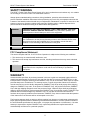
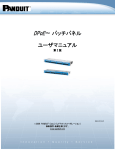
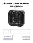
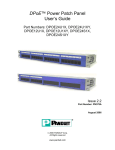
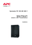
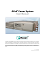
DPoE™ Power System
User Manual
Copyright © 2012 PANDUIT Corp. All rights reserved. No part of this book shall be reproduced, stored in a retrieval
system, or transmitted by any means, electronic, mechanical, photocopying, recording or otherwise, without written
permission from PANDUIT. No patent liability is assumed with respect to the use of the information contained herein.
Although every precaution has been taken in the preparation of this book, PANDUIT assumes no responsibility for
errors or omissions. Neither is any liability assumed for damages resulting from the use of the information contained
herein.
Part # PN380D
Published February 2012
DPOE™ Power System User Manual
Part Number: PN380D
SAFETY WARNING
The DPOE™ Power Patch Panel Power System is for use in restricted access locations only. It is suitable
for mounting on concrete or other non-combustible surfaces.
Always observe standard safety precautions during installation, operation and maintenance of this
product. Read the installation instructions before performing any work. Only a competent technician who
is aware of the hazards involved should carry out adjustment, maintenance or repairs. Do not work on the
system or connect or disconnect cables during periods of lightning activity. Ultimate disposal of this
product should be handled according to all national laws and regulations.
WARNING:
HAZARDOUS VOLTAGE AND ENERGY LEVELS ARE PRESENT THAT CAN
PRODUCE SERIOUS SHOCKS AND BURNS. Only authorized, qualified, and
trained personnel should attempt to work on this equipment.
CAUTION:
The plug end of the cords used to connect to the Alternating Current (AC) source
are considered to be the primary disconnect means, and reasonable access must
be given to the plug and receptacle area. The receptacle must be fed with a
breaker or fuse according to the instructions in this guide.
CAUTION:
ALL RECTIFIERS EMPLOY INTERNAL DOUBLE POLE/NEUTRAL FUSING.
FCC Compliance Statement
This device complies with Part 15 of FCC Rules. Operation is subject to the following two conditions:
1. This device may not cause harmful interference, and
2. This device must accept any interference received, including interference that may cause undesired
operation.
WARNING:
Changes or modifications to this unit not expressly approved by the party
responsible for the compliance could void the user's authority to operate this
equipment.
WARRANTY
Unless otherwise specified, all products presented in this user's guide are warranted against defects in
material and workmanship for a period of one year from the date of invoice by PANDUIT® Corp. to the
initial purchaser. During the warranty period PANDUIT Corp. will, at its discretion, either repair or replace
products that prove to be defective. For warranty service or repair, the product claimed to be defective
must be returned to a service facility designated by PANDUIT Corp. Buyer shall prepay all the shipping
charges to PANDUIT Corp. and if, in the opinion of PANDUIT Corp., the product is defective, PANDUIT
Corp. shall pay shipping charges to return the product to Buyer. However, Buyer shall pay all shipping
charges, duties and taxes for products returned to PANDUIT Corp. from another country. PANDUIT Corp.
warrants that its firmware designed by PANDUIT Corp. for use with an instrument will execute its
functions when properly installed on that instrument. PANDUIT Corp. does not warrant that the operation
of the instrument or the firmware will be uninterrupted or error-free.
The foregoing warranty shall not apply to defects resulting from improper or inadequate maintenance by
Buyer (buyer-supplied firmware or interfacing unauthorized modification or misuse, operation outside of
the environmental specifications for the product, or improper site preparation or maintenance). No other
warranty is expressed or implied. PANDUIT Corp. specifically disclaims the implied warranties of
merchantability and fitness for a particular purpose.
ii
DPOE™ Power System User Manual
Part Number: PN380D
The remedies provided herein are Buyer's sole and exclusive remedies. PANDUIT Corp. shall not be
liable for any direct, indirect, special, incidental or consequential damages, whether based on contract,
tort or other legal theory.
Unless otherwise specified by PANDUIT Corp., opening this product by unauthorized personnel will void
this warranty.
TRADEMARKS
DPOE™ and Contour Crimp are trademarks of PANDUIT Corporation. All other trademarks are the
property of their respective owners.
iii
DPOE™ Power System User Manual
Part Number: PN380D
TABLE OF CONTENTS
SAFETY WARNING ................................................................................................................... ii
FCC Compliance Statement .................................................................................................... ii
WARRANTY ............................................................................................................................... ii
TRADEMARKS ......................................................................................................................... iii
OVERVIEW ............................................................................................................................... 1
INSTALLATION......................................................................................................................... 2
Package Contents .................................................................................................................. 2
Heat Dissipation ..................................................................................................................... 3
AC Input Wiring ...................................................................................................................... 3
DC Output Wiring Sizing ........................................................................................................ 4
Connecting to a DPoE™ Power Patch Panel or Compact 8 Midspan .................. 5
Torque Settings ...................................................................................................................... 7
Required Tools ....................................................................................................................... 7
Site and Equipment Preparation............................................................................................. 7
POWER PLANT MOUNTING AND WIRING ............................................................................. 8
Mechanical Mounting ............................................................................................................. 8
Support Shelf Mounting (Optional) ......................................................................................... 8
AC Input ................................................................................................................................. 9
DC Output .............................................................................................................................. 9
TEST AND TURN-ON...............................................................................................................11
Rectifiers ...............................................................................................................................11
Power Up ..............................................................................................................................11
Short Circuit and Current Limit ..............................................................................................11
TROUBLESHOOTING..............................................................................................................12
Figures
Figure 1 : Top View of Power Chassis with Power Rectifiers Installed ....................................... 1
Figure 2: Individual AC Feed Wiring Architecture ....................................................................... 4
Figure 3: DC Wire Diagram ........................................................................................................ 5
Figure 4: Connecting to a DPoE™ Power Patch Panel or Compact 8 Midspan .......................... 6
Figure 5: Chassis (Front View) ................................................................................................... 8
Figure 6: Optional Rack Mount Shelf .......................................................................................... 8
Figure 7: Cord Bracket ............................................................................................................... 9
Figure 8: Chassis (Rear View) - AC Connections ....................................................................... 9
Figure 9: Securing Cord Bracket to Chassis............................................................................... 9
Figure 10: Chassis (Front View) - GMT fuse holder ..................................................................10
Figure 11: GMT 7.5A DC Power Fuse .......................................................................................10
Figure 12: Chassis (Rear View) - DC Connections ....................................................................10
Figure 13: Installing or Removing Rectifiers ..............................................................................11
List of Tables
Table 1: Package Contents ........................................................................................................ 2
Table 2: DPOE™ Power Components Available from PANDUIT ................................................ 3
Table 3: Heat Dissipation ........................................................................................................... 3
iv
DPOE™ Power System User Manual
Part Number: PN380D
Table 4: Recommended AC Circuit Breaker and Wire Sizes ...................................................... 4
Table 5: Minimum Recommended DC AWG for 90°C Cabling for Unprotected Outputs............. 6
Table 6: Recommended Torque Settings ................................................................................... 7
Table 7: PANDUIT Corp. Contact Information ............................................................................ 7
Table 8: Troubleshooting ..........................................................................................................12
v
DPOE™ Power System User Manual
Part Number: PN380D
OVERVIEW
The DPOE™ Power Patch Panels and the DPOE™ Compact 8 Midspan provide a reliable and costeffective solution for Power over Ethernet (PoE) applications, complaint with the IEEE 802.3af-2003
specifications or the alternate PoE (Cisco Legacy) specifications. These DPOE™ Power over Ethernet
Systems allow centralized powering of network devices, such as Voice over Internet Protocol-based
(VoIP) telephones, IP security and surveillance cameras, or wireless access point (WAP) devices, over
the same cabling used to send data. DPOE™ Power over Ethernet Systems fit into 19" racks and occupy
1RU height.
The DPOE™ Power over Ethernet Systems may be powered individually using a DPOE™ Power Supply
(PANDUIT part # DPOEPWRB120Y), which delivers 120 watts at 48 Volts of Direct Current (VDC) to a
single DPOE™ Power Patch Panel or DPOE™ Compact 8 Midspan. However, 120 watts may not be
enough power to support all the Powered Devices (PD) connected to the panel or powered midspan. In
these cases, or in cases of multiple DPOE™ Power over Ethernet Systems, a larger power system is
often required. One option is to use the DPOE™ Power System Chassis with Power Rectifiers, herein
referred to as the DPOE™ Power System.
The DPOE™ Power System uses a modular design to supply power at 48 VDC to DPOE™ Power over
Ethernet Systems. The DPOE™ Power System consists of a chassis (PANDUIT part # DPOEPWRCU),
which can accommodate up to three rectifiers (1250 watt rectifiers), depending on the current and future
power requirements for the DPOE™ Power over Ethernet Systems being used.
Figure 1 : Top View of Power Chassis with Power Rectifiers Installed
The DPOE™ Power System accepts an Alternating Current Voltage (VAC) between 100 and 240 VAC
(47 to 63 Hz) and produces a regulated output of 42 - 56 VDC capable of delivering a max of 10 Amperes
(A) of Direct Current (DC) in an ambient operating temperature range of -40° Celsius (C) to +70° C per
output channel.
1
DPOE™ Power System User Manual
Part Number: PN380D
INSTALLATION
CAUTION:
Observe all local and national electrical, environmental, and workplace codes.
Each chassis should be fed from a dedicated AC branch circuit of a TN or IT power system.
CAUTION:
The plug ends on the power cords used for the AC connections are considered to
be the primary disconnect means. Reasonable access must be given to the plug
and receptacle area. The receptacle must be fed with a breaker or fuse according
to Table 4: Recommended AC Circuit Breaker and Wire Sizes.
Use single hole, Underwriters Laboratory (U.L.) listed lugs for the bulk DC connection to prevent lug
rotation and inadvertent contact with other circuits. Terminal strip connections use compression screws.
Class 1 wire is recommended for all DC connections. Minimum wire sizes for protected and unprotected
circuits are shown in Table 5: Minimum Recommended DC AWG for 90°C Cabling for Unprotected
Outputs , respectively. In practice, loop voltage drop considerations will usually dictate larger than
minimum safe wire size.
For connection and mounting torque requirements see Table 6: Recommended Torque Settings.
PANDUIT Corp. does not recommend shipping the chassis with the rectifiers installed. Rectifiers should
be shipped in their separate boxes.
Package Contents
The DPOE™ Power System chassis is shipped with the following included items.
Table 1: Package Contents
Item
DPOE™ Power System User
Manual
QNTY.
Notes
1
This manual
Cord Brackets
3
Secures individual power cords to the rear of the DPOE™
Power System Chassis
Screws with integrated
washers
4
Secures DPOE™ Power System chassis to a 19” rack
Nuts
2
Secures the lugs to the bulk DC connection on the rear of
the DPOE™ Power System chassis
Screws with integrated
washers
6
#4-40 screws for securing the cord brackets to the back
of the DPOE™ Power System chassis
GMT Fuses
20
(4) 5 amp fuses and (16) 7.5 amp fuses
2
DPOE™ Power System User Manual
Part Number: PN380D
Table 2: DPOE™ Power Components Available from PANDUIT
PANDUIT Part Number
Description
DPOEPWRB120Y
Individual power supply - 120 watt power supply –
48 volt output
DPOEPWRCU
Unmanaged power chassis (supports 3 rectifiers)
DPOEPWRR1250
1250 watt rectifier for use in power chassis
DPOEPWRF7.5
7.5 amp fuse (package of 8)
DPOEPWRF5
5 amp fuse (package of 4)
CORD-A
Power cord for Australia
CORD-E
Power cord for Europe
CORD-S15
Power cord for North America
CORD-J15
Power Cord for Japan
CORD-U
Power cord for the U.K.
Heat Dissipation
The following table displays the maximum and typical British Thermal Units per hour (BTU/hr) of heat
dissipated from each rectifier. The maximum is calculated at 90 VAC, and typical is calculated at 230
VAC.
Table 3: Heat Dissipation
Part Number
Typical BTU/hr
Max BTU/hr
DPoEPWRR1250
451
833
AC Input Wiring
The DPOE™ Power System chassis uses an individual AC feed architecture (See
Figure 2: Individual AC Feed Wiring Architecture), which requires one AC feed per rectifier. Up to three,
AC connections are made using the IEC320 receptacles on the rear of the chassis (See
Figure 8: Chassis (Rear View) - AC Connections).
Connect each feed, using the appropriate power cord as listed in Table 2: DPoE™ Power Components
Available into the appropriate receptacle on the back of the system. Cord securing brackets are included
to secure the AC plugs to the chassis (See Figure 9: Securing Cord Bracket to Chassis).
3
DPOE™ Power System User Manual
Part Number: PN380D
N+1 DC Out
Rectifiers
1
2
3
Feed 1
AC In
Feed 2
Feed 3
Figure 2: Individual AC Feed Wiring Architecture
Each individual AC feed should be protected using a circuit breaker as listed in Table 4: Recommended
AC Circuit Breaker and Wire Sizes.
Table 4: Recommended AC Circuit Breaker and Wire Sizes
Type of
Feed
Number of
Rectifiers
on an AC
Feed
Individual
AC Feed
1
Part Number
Maximum
Input
Voltage
Maximum
Rated AC
Current
(A)
Circuit
Breaker
Minimum
value (A)
90° C
Minimum
Wire
Gauge
(AWG) to
use at 30°
C ambient
DPOEPWRR1250
90
17.6
20
12
DPOEPWRR1250
180
8.8
15
14
DC Output Wiring Sizing
There are two main considerations for sizing DC wire, ampacity and voltage drop. Ampacity refers to the
safe current-carrying level as specified by U.S.-based organizations such as Underwriters Laboratories
and the National Fire Prevention Association, which publishes the National Electric Code (NEC). Voltage
drop is simply the amount of voltage loss in a length of wire due to ohmic resistance of the conductor. DC
wire may be sized for either ampacity or voltage drop depending on branch load loop length and
conductor heating. In general, ampacity considerations will drive wire selection for short loop lengths (less
than 50 feet) and voltage drop will drive wire selection for long loop lengths (greater than 50 feet). The
National Electric Code table 310.16 provides ampacity values for various sizes, bundles, and insulation
temperature rated wire.
4
DPOE™ Power System User Manual
CAUTION:
Part Number: PN380D
ALWAYS FOLLOW NEC GUIDELINES AND YOUR LOCAL COMPANY
PRACTICES WHEN SELECTING DC WIRING AND PROTECTION.
Table 5: Minimum Recommended DC AWG for 90°C Cabling for Unprotected Outputs shows
recommended wire sizes based on ampacity. The maximum current rating for the chassis is 100 A.
Rectifiers
1
2
14
Single hole bulk
battery connections
(¼" studs)
14 GMT Fuse
Connections
Figure 3: DC Wire Diagram
Each chassis is equipped with 14 GMT style fuse connections and an unfused bulk DC connection
located on the rear of the chassis. The GMT fused connections are made on “lugless” terminal blocks
with compression screws. The terminal blocks will accept wire sizes up to 12AWG.
The bulk DC connection may be used as a battery input or as an unfused bulk output. The connections
require a terminal lug (1/4” single hole lug with a max tongue width of 0.63” or less), such as PANDUIT
part # LCA4-14-L. Size wires based on the total rectifier capacity and choose conductor size according to
Table 5: Minimum Recommended DC AWG for 90°C Cabling for Unprotected Outputs .
Connecting to a DPoE™ Power Patch Panel or Compact 8 Midspan
Each DPOE™ Power over Ethernet System is shipped with a keyed power connector harness and two
butt splices (PANDUIT part # BSV14X) for use in connecting the panel to the power source. The butt
splices included with the DPOE™ Power Patch Panel will support 14 - 16 AWG solid or stranded wire.
WARNING:
Connect each separate DPOE™ Power Patch Panel or Compact 8 Midspan to the
rear of the DPOE™ Power System using one of the 14 GMT-fused outputs per
panel.
Do not wire multiple untis to a single output on the DPOE™ Power System.
5
DPOE™ Power System User Manual
Part Number: PN380D
Figure 4: Connecting to a DPoE™ Power Patch Panel or Compact 8 Midspan
NOTE:
The included power harness has two wires for the A-feed power only (pins 1 & 2).
The DPOE™ Power Patch Panel or Compact 8 Midspan supports an optional
redundant B-feed power option, but the terminals and wire leads are not attached to
the power harness.
Contact PANDUIT Technical Support for more information about connecting the
redundant B-Feed power. (PANDUIT part # DPOEPWRDUAL should be used for
redundant powering options)
WARNING:
The power supply connections on the DPOE™ Power Patch Panel and the
Compact 8 Midspan are polarized. They will not function if power is wired
improperly.
Table 5: Minimum Recommended DC AWG for 90°C Cabling for Unprotected
Outputs
1
Total Rectifier Current Rating (A)
Wire and Lug Gauge
(AWG) using 90° C wire
10
20
25
(NEC Table 310.16)
16
14
12
1
Table 310.16 uses Table 3B – Sizes of Conductors from BS EN 60950:2000, “Safety of Information
Technology Equipment,” December 2000 for non-building wiring.
6
DPOE™ Power System User Manual
Part Number: PN380D
Torque Settings
The following table shows recommended torque settings for all mechanical and electrical connections
according to screw or nut size in inch pounds (in-lbs).
Table 6: Recommended Torque Settings
Screw or Nut Size
Toque (in-lbs)
4-40
6-32
8-32
10-32
12-24
¼-20
6
12
22
37
50
65
Required Tools
The DPOE™ Power System is designed to be installed with commonly available tools:
•
•
•
•
•
•
#1 & #2 flat blade and Phillips head screwdrivers
Torque wrench
7/16” socket, ¼” drive
Wire and cable strippers (PANDUIT part number CT-100)
Wire and cable crimpers (such as PANDUIT part CT-1550, CT-1551, CT-1570, CT-1700
TM
Contour Crimp Controlled Cycle Crimp Tools) (used for optional bulk DC connection)
Site and Equipment Preparation
Prior to unpacking the DPOE™ Power System, note any physical package damage that could indicate
potential damage to the contents. After removing the DPOE™ Power System from the boxes and packing
material, inspect for shipping and/or other damage. Any problems should be reported to PANDUIT
technical support.
Table 7: PANDUIT Corp. Contact Information
PANDUIT Technical Support
Fax:
1-708-444-6993
E-mail: [email protected]
PANDUIT Product Installation Instructions
www.panduit.com/resources/install_maintain.asp
Worldwide Subsidiaries and Sales Offices
www.panduit.com
Have all tools, wire, cables, hardware, etc., within easy reach. To the extent possible, ensure a clean
(free of debris, dust, foreign material, etc.) work environment. Care should be taken in the installation
process to prevent wire clippings from getting into the equipment.
NOTE:
If possible, the rectifiers should remained sealed in their shipping boxes until the
chassis wiring is complete. Rectifiers should not be inserted until all DPOE™
components are properly connected.
7
DPOE™ Power System User Manual
Part Number: PN380D
POWER PLANT MOUNTING AND WIRING
WARNING:
Ensure all AC and DC power sources are off and disconnected.
WARNING:
Power to the DPoE power system chassis should be disconnected prior to
performing any power line maintenance to prevent damage to the rectifier.
Mechanical Mounting
The DPOE™ Power System chassis is installed in a standard EIA 19” rack. It is recommended that one
person lift the chassis into the proper rack place while another person installs the supplied mounting
screws. Tighten the screws with a torque wrench to the setting according to Table 6: Recommended
Torque Settings.
Mounting Brackets
Slots for Rectifiers
In shelf
distribution
Figure 5: Chassis (Front View)
Support Shelf Mounting (Optional)
After securing the DPOE™ Power System chassis with mounting screws in the front, an optional rack
mount shelf may be installed underneath the chassis on the backside of the rack to alleviate potential
sagging of the chassis unit, due to weight distribution when mounted on a 2-post rack. PANDUIT offers a
1RU shelf (part # SRM19FM1) with a load rating of 30 lbs that will help support the chassis. For optimum
saftety, a 2 RU shelf (PANDUIT part # SRM19FM2 – shown below) with a load rating of up to 50 lbs may
be installed.
Attach power chassis to front of rack
using Mounting Brackets
Optional Rack Mount Shelf
(attached to back of rack with
shelf turned upside down)
Figure 6: Optional Rack Mount Shelf
8
DPOE™ Power System User Manual
NOTE:
Part Number: PN380D
Optional rack shelf is actually installed upside down to the rear of the rack to allow
power chassis to rest on the flat side of the shelf.
AC Input
Slip the cord bracket around each cord (PANDUIT part # CORD-****), as shown in Figure 7: Cord
Bracket. Plug the cord into the proper receptacle on the back of the chassis (See
Figure 8: Chassis (Rear View) - AC Connections), then secure the cord bracket to the chassis using the
provided screws (See Figure 9: Securing Cord Bracket to Chassis).
Figure 7: Cord Bracket
Figure 8: Chassis (Rear View) - AC Connections
Figure 9: Securing Cord Bracket to Chassis
DC Output
DC connections are accomplished via the rear terminal blocks and bulk output connection as shown in
Figure 12: Chassis (Rear View) - DC Connections. GMT-fused connections are accomplished via the
rear compression screw terminal block that will accept wires sizes up to 12 AWG. If a fuse is not in
9
DPOE™ Power System User Manual
Part Number: PN380D
corresponding slot, then place wire in output and corresponding return, and compress the screws to 4 inlbs. Place a fuse into the corresponding position into the fuse holder as shown in Figure 10: Chassis
(Front View) - GMT fuse holder.
The DPOE™ Power System Chassis allows a bulk DC connection as shown in Figure 12: Chassis (Rear
View) - DC Connections. The bulk DC connection may be optionally used to ensure continued power to
the connected DPOE™ Power Patch Panels and the PD connected to the panels in the event of a power
failure. This connection may be used as a battery input or as an unfused bulk output. The bulk DC
connection requires properly crimped terminal lugs (1/4” single hole lug with a max tongue width of 0.63”
or less). Terminal lugs (such as PANDUIT part # LCA4-14-L for use with #3 or #4 AWG stranded wire or
#2 AWG solid wire) and crimping tools (such as the PANDUIT part #s CT-1550, CT-1551, CT-1570, or
CT-1700) are available from PANDUIT Corp. The bulk output terminals feature a break-off plastic piece to
prevent inadvertent contact with the terminals. If using the bulk DC output feature, carefully break off each
plastic tab before securing the terminal lugs.
Size wires based on the total rectifier capacity and choose conductor size according to Table 5:
Minimum Recommended DC AWG for 90°C Cabling for Unprotected Outputs . For battery or bulk
DC connections, place lug on the corresponding positive and negative studs, and secure the connections
with the included nuts.
Figure 10: Chassis (Front View) - GMT fuse holder
Figure 11: GMT 7.5A DC Power Fuse
GMT fused return
output connections
(White wire on
Power Patch Panel
Connector Kit)
Positive Output
or Battery Input
Negative Output
or Battery Input
GMT fused negative
output connections
(Black wire on
Power Patch Panel
Connector Kit)
Figure 12: Chassis (Rear View) - DC Connections
10
DPOE™ Power System User Manual
Part Number: PN380D
TEST AND TURN-ON
Once all AC and DC connections have been secured and checked, install each rectifier sequentially by
sliding and latching it into the chassis as illustrated in the section below.
Rectifiers
The rectifiers for use in the DPOE™ Power System are equipped with Light Emitting Diodes (LEDs) on
the front panel as a means to indicate problems with that specific rectifier. The rectifiers are designed as
modular, field replaceable units.
Power Up
Plus all AC power cords into an appropriate Power Supply Unit (PSU), or Uninterruptible Power Supply
(UPS).
In the event that a rectifier needs to be removed, press the latch button on the front of the rectifier to
release the latch handle. Pull the latch handle until the rectifier clears the rear connector on the chassis,
then gently slide it out of the rear connector. With the latch handle open on the replacement rectifier, slide
the rectifier in until it connects with the backplane. While pressing the latch button down, use the latch
handle to gently ease the rectifier into the rear connector. When the rectifier is properly seated, releasing
the latch button will hold the latch handle in place.
WARNING:
The latch handle must be open for installation or removal of a rectifier. Attempting
to install a rectifier with the latch handle closed will result in mechanical damage to
the rectifier and the DPOE™ Power System chassis.
The rectifier will power up and configure itself. It will start in high fan speed mode and reduce the speed
according to the ambient and plant conditions within 10 seconds.
Figure 13: Installing or Removing Rectifiers
Short Circuit and Current Limit
ILimit can be adjusted up to +105% of the rated current of the rectifier. The system voltage will remain
constant up to ILimit at which point the system voltage will drop quickly toward 0 VDC. Once a 48V rectifier
output drops below 12 VDC for more than 5 seconds, the system will shut down. The system will
automatically restart after 60 seconds, and will continue until the short circuit is cleared.
11
DPOE™ Power System User Manual
Part Number: PN380D
TROUBLESHOOTING
The modular nature of this DPOE™ Power System makes diagnostics and repair easy. Make sure that all
rectifiers are properly seated and latched into their respective slots. Make sure all power and signal
connectors are properly mated.
Table 8: Troubleshooting
Alarm
Problem
Possible Solution
DC OK LED is extinguished
This rectifier has stopped
outputting power
Rectifier failed. Replace this
unit.
AC OK and all LEDs are
extinguished
Commercial power has been
lost to the specified rectifier(s)
Reset commercial circuit
breaker to the dedicated AC
circuit that feeds the system.
Seek alternative power source
until power is restored.
Fuse Open
A fuse is in the open state
Replace the open fuse
12