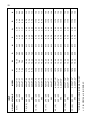
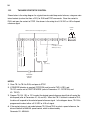
1
AC300 Series Installation and Operation Manual U S E R ’ S M A N UA L USER’S MANUAL Variable Speed AC Motor Drives Table of Contents 1.0 GENERAL PRODUCTS COVERED IN THIS MANUAL . . . . . . . . . . . . . . . . . . . . . . . . . PRODUCT CHANGES . . . . . . . . . . . . . . . . . . . . . . . . . . . . . . . . . . . . . . . . WARRANTY . . . . . . . . . . . . . . . . . . . . . . . . . . . . . . . . . . . . . . . . . . . . . . . . RECEIVING . . . . . . . . . . . . . . . . . . . . . . . . . . . . . . . . . . . . . . . . . . . . . . . . CUSTOMER MODIFICATION . . . . . . . . . . . . . . . . . . . . . . . . . . . . . . . . . . . 1 1 1 1 2 2 2.0 AC300 SPECIFICATIONS . . . . . . . . . . . . . . . . . . . . . . . . . . . . . . . . . . . . . . . . . . 3 3.0 AC300 MODEL DESIGNATION CODE . . . . . . . . . . . . . . . . . . . . . . . . . . . . . . . . 5 4.0 AC300 DIMENSIONS . . . . . . . . . . . . . . . . . . . . . . . . . . . . . . . . . . . . . . . . . . . . . 6 5.0 AC300 RATINGS . . . . . . . . . . . . . . . . . . . . . . . . . . . . . . . . . . . . . . . . . . . . . . . . 13 6.0 THEORY . . . . . . . . . . . . . . . . . . . . . . . . . . . . . . . . . . . . . . . . . . . . . . . . . . . . . . . 19 DESCRIPTION OF AC MOTOR OPERATION . . . . . . . . . . . . . . . . . . . . . . . 19 DRIVE FUNCTION DESCRIPTION . . . . . . . . . . . . . . . . . . . . . . . . . . . . . . . 23 7.0 INSTALLATION . . . . . . . . . . . . . . . . . . . . . . . . . . . . . . . . . . . . . . . . . . . . . . . . . 8.0 INPUT AC REQUIREMENTS . . . . . . . . . . . . . . . . . . . . . . . . . . . . . . . . . . . . . . . 27 9.0 VOLTAGE SELECTION . . . . . . . . . . . . . . . . . . . . . . . . . . . . . . . . . . . . . . . . . . . 29 10.0 POWER WIRING . . . . . . . . . . . . . . . . . . . . . . . . . . . . . . . . . . . . . . . . . . . . . . . . 30 11.0 AC300 POWER WIRING DIAGRAM . . . . . . . . . . . . . . . . . . . . . . . . . . . . . . . . . . 31 12.0 INITIAL POWER UP . . . . . . . . . . . . . . . . . . . . . . . . . . . . . . . . . . . . . . . . . . . . . . 32 13.0 KEYPAD CONTROL . . . . . . . . . . . . . . . . . . . . . . . . . . . . . . . . . . . . . . . . . . . . . . 35 KEYPAD FUNCTIONS . . . . . . . . . . . . . . . . . . . . . . . . . . . . . . . . . . . . . . . . . 35 AC300 DISPLAY . . . . . . . . . . . . . . . . . . . . . . . . . . . . . . . . . . . . . . . . . . . . . 36 14.0 CONTROL WIRING . . . . . . . . . . . . . . . . . . . . . . . . . . . . . . . . . . . . . . . . . . . . . . 44 GENERAL . . . . . . . . . . . . . . . . . . . . . . . . . . . . . . . . . . . . . . . . . . . . . . . . . 44 START/STOP AND SPEED CONTROL . . . . . . . . . . . . . . . . . . . . . . . . . . . . 45 15.0 AC300 CONTROL WIRING DIAGRAMS . . . . . . . . . . . . . . . . . . . . . . . . . . . . . . . AC300 TERMINAL STRIP . . . . . . . . . . . . . . . . . . . . . . . . . . . . . . . . . . . . . . TWO-WIRE START/STOP CONTROL . . . . . . . . . . . . . . . . . . . . . . . . . . . . . THREE-WIRE START/STOP CONTROL . . . . . . . . . . . . . . . . . . . . . . . . . . . SPEED POT AND PRESET SPEED CONTROL . . . . . . . . . . . . . . . . . . . . . 25 53 53 54 55 56 Table of Contents (continued) 16.0 PROGRAMMING THE AC300 DRIVE . . . . . . . . . . . . . . . . . . . . . . . . . . . . . . . .57 PROGRAMING THE PARAMETERS . . . . . . . . . . . . . . . . . . . . . . . . . . . . .57 PARAMETER ACCESS USING SPEED DIAL . . . . . . . . . . . . . . . . . . . . . .60 17.0 PARAMETER MENU . . . . . . . . . . . . . . . . . . . . . . . . . . . . . . . . . . . . . . . . . . . . .61 18.0 DESCRIPTION OF PARAMETERS . . . . . . . . . . . . . . . . . . . . . . . . . . . . . . . . . .64 19.0 TROUBLESHOOTING . . . . . . . . . . . . . . . . . . . . . . . . . . . . . . . . . . . . . . . . . . .101 1 1.0 General 1.1 PRODUCTS COVERED IN THIS MANUAL This manual covers the Minarik AC300 Series Variable Frequency Drive. 1.2 PRODUCT CHANGES Minarik Corporation reserves the right to discontinue or make modifications to the design of its products without prior notice, and holds no obligation to make modifications to products sold previously. Minarik Corporation also holds no liability for losses of any kind which may result from this action. Latest revisions of Minarik manuals are available for download at www.minarikdrives.com 1.3 WARRANTY Minarik Corporation warrants the AC300 Series AC motor control to be free of defects in material and workmanship for a period of twelve months from the date of sale to the user. An AC300 Series control, or any component contained therein, which under normal use, becomes defective within the stated warranty time period, shall be returned to Minarik Corporation, freight prepaid, for examination (contact Minarik Corporation for authorization prior to returning any product). 2 Minarik Corporation reserves the right to make the final determination as to the validity of a warranty claim, and sole obligation is to repair or replace only components which have been rendered defective due to faulty material or workmanship. No warranty claim will be accepted for components which have been damaged due to mishandling, improper installation, unauthorized repair and/or alteration of the product, operation in excess of design specifications or other misuse, or improper maintenance. Minarik Corporation makes no warranty that its products are compatible with any other equipment, or to any specific application, to which they may be applied and shall not be held liable for any other consequential damage or injury arising from the use of its products. This warranty is in lieu of all other warranties, expressed or implied. No other person, firm or corporation is authorized to assume, for Minarik Corporation, any other liability in connection with the demonstration or sale of its products. 1.4 RECEIVING Inspect all cartons for damage which may have occurred during shipping. Carefully unpack equipment and inspect thoroughly for damage or shortage. Report any damage to carrier and/or shortages to supplier. All major components and connections should be examined for damage and tightness, with special attention given to PC boards, plugs, knobs and switches. 1.5 CUSTOMER MODIFICATION Minarik Corporation, its sales representatives and distributors, welcome the opportunity to assist our customers in applying our products. Many customizing options are available to aid in this function. Minarik Corporation cannot assume responsibility for any modifications not authorized by its engineering department. 3 2.0 AC300 SPECIFICATIONS Storage Temperature -20° to 70° C Ambient Operating Temperature Chassis (With 2.5, 6, and 8 kHz carrier, derate for higher carriers) -10° to 55° C Type 1 (IP 31) -10° to 50° C Type 4 (IP 65) -10° to 40° C Type 12 (IP 54) -10° to 40° C Ambient Humidity Less than 95% (non-condensing) Maximum Altitude 3300 feet (1000 m) above sea level, without derating. Input Line Voltages 240/120 VAC, 240/200 VAC, 480/400 VAC, and 590/480 VAC Input Voltage Tolerance +10%, -15% Input Frequency Tolerance 48 to 62 Hz Output Wave Form Sine Coded PWM 4 Output Frequency 0-120 Hz, Optional up to 1000 Hz Carrier Frequency 2.5 kHz to 14 kHz Frequency Stability + 0.00006% / °C Service Factor 1.00 Efficiency > 97% throughout speed range Power Factor (displacement) > 0.96 Overload Current Capacity 150% of output rating for 60 seconds 180% of output rating for 30 seconds Speed Reference Follower 0-10 VDC, 4 - 20 mA Control Voltage 15 VDC Analog Outputs 0 - 10 VDC, or 2 - 10 VDC Proportional to speed and load Digital Outputs Form C relay: 2 A at 28 VDC or 120 VAC Open-collector outputs: 40 mA at 30 VDC 5 3.0 AC300 MODEL DESIGNATION CODE The model number of an AC300 Series drive gives a full description of the basic drive unit (see example below). EXAMPLE: AC324T-3.7P (AC300, 480 VAC, 5 HP, NEMA 1 Enclosure, with a Remote Keypad Assembly) AC3 2 4 T -3.7 Series: AC3 = AC300 Series Variable Speed AC Motor Drive Enclosure Type: 0 = Chassis- Open Enclosure with Cover Removed 2 = NEMA 1- General Purpose, vented 3 = NEMA 4 - Water-tight and Dust-tight 4 = NEMA 12- Dust-tight and Oil-tight 5 = NEMA 4X - Water tight, Dust tight and Corrosion Resistant Input Voltage: 1 = 240/120 VAC (For 110, 115, 120, 230 and 240 VAC; 50 or 60 Hz) 2 = 240/200 VAC (For 208 and 240 VAC; 50 or 60 Hz) 4 = 480/400 VAC (For 380, 415, 440, 460, and 480 VAC; 50 or 60 Hz) 5 = 590/480 VAC (For 440, 460, 480, 575, and 600 VAC; 50 or 60 Hz) Input Phase: S = Single phase input only. T = Three phase input only. Horsepower: (Kilowatts) 0.2 = 1/4 Hp 3.7 = 5 Hp 22 = 0.4 = 1/2 Hp 5.5 = 7 1/2 Hp 30 = 30 Hp 40 Hp 0.75 = 1 Hp 7.5 = 10 Hp 37 = 50 Hp 1.1 = 1 1/2 Hp 11 = 15 Hp 45 = 60 Hp 1.5 = 2 Hp 15 = 20 Hp 2.2 = 3 Hp 18.5 = 25 Hp Standard Options: H = Additional Form "C" Relay circuit board J = Dynamic Breaking circuit board K = Additional Relay & Dynamic Braking board (not available on all Hp sizes --consult factory) = No character when this type of option is not specified Interface Options: P = Remote Keypad Assembly = No character when this type of option is not specified. P N V R 1.00” Mounting Tab Detail T Dia. Slot U IF W = 10.26” T = 0.28” U = 0.44” V = 0.24” IF W < 7.86” T = 0.20” U = 0.34” V = 0.19” Chassis and Type 1 Enclosed S Dia. W 4.1 Conduit Holes: S Dia. 0.88” Dia. H AC300 DIMENSIONS P Q R D 4.0 Q W 6 INPUT 2 (1.5) 1.5 (1.1) AC322T-1.5 AC324T-1.5 AC325T-1.5 480 / 400 590 7.50 7.50 7.50 7.50 7.50 7.50 7.50 7.50 7.50 6.12 6.12 6.12 6.12 4.70 6.12 6.12 4.70 4.70 4.70 4.70 6.12 4.70 4.70 6.12 4.70 W 4.22 4.22 5.12 5.12 4.33 4.22 4.22 3.63 3.63 4.33 4.33 4.22 3.63 3.63 3.63 3.33 D 3.77 3.77 3.77 3.77 2.35 3.77 3.77 2.35 2.35 2.35 2.35 3.77 2.35 2.35 3.77 2.35 N 2.40 2.40 3.30 3.30 2.60 2.40 2.40 1.90 1.90 2.60 2.60 2.40 1.90 1.90 1.80 1.60 P DIMENSIONS - CHASSIS AND TYPE 1 ENCLOSED AC322S-1.5 240 AC322T-1.1 240 / 200 240 / 200 AC322S-1.1 AC325T-0.75 590 AC321S-1.1 AC324T-0.75 480 / 400 240 AC322T-0.75 240 / 120 7.50 AC322S-0.75 240 240 / 200 7.50 7.50 7.50 7.50 7.50 7.50 H AC321S-0.75 AC322T-0.4 240 / 200 240 / 120 AC322S-0.4 240 1 (0.75) AC321S-0.4 240 / 120 0.5 (0.37) MODEL AC321S-0.2 VOLTAGE 0.25 (0.18) 240 / 120 HP (kW) 1.37 1.37 1.37 1.37 1.37 1.37 1.37 1.37 1.37 1.37 1.37 1.37 1.37 1.37 1.37 1.37 Q 5.50 5.50 5.50 5.50 5.50 5.50 5.50 5.50 5.50 5.50 5.50 5.50 5.50 5.50 5.50 5.50 R 0.88 0.88 0.88 0.88 0.88 0.88 0.88 0.88 0.88 0.88 0.88 0.88 0.88 0.88 0.88 0.88 S 7 15 (11) 10 (7.5) 7.5 (5.5) AC324T-11 AC325T-11 590 12.75 11.25 12.75 9.38 9.38 11.25 9.38 9.38 9.38 7.88 7.50 7.88 7.50 7.50 7.50 7.50 H 7.86 7.86 7.86 7.86 7.86 7.86 7.86 7.86 7.86 7.86 6.12 7.86 6.12 6.12 6.12 6.12 W 6.84 6.84 6.84 7.40 6.84 6.84 6.25 6.25 6.84 5.94 5.12 5.94 5.12 5.12 5.12 5.12 D 3.93 3.93 3.93 3.93 3.93 3.93 5.13 5.13 3.93 5.13 3.77 5.13 3.77 3.77 3.77 3.77 N 4.19 4.19 4.19 4.19 4.19 4.19 3.95 3.95 4.19 3.95 3.30 3.95 3.30 3.30 3.30 3.30 P DIMENSIONS - CHASSIS AND TYPE 1 ENCLOSED (continued) AC322T-11 AC325T-7.5 590 480 / 400 AC324T-7.5 240 / 200 AC322T-7.5 AC325T-5.5 590 480 / 400 AC324T-5.5 240 / 200 AC322T-5.5 AC326T-3.7 590 480 / 400 AC324T-3.7 240 / 200 AC322T-3.7 AC325T-2.2 590 480 / 400 AC324T-2.2 480 / 400 240 / 200 AC322T-2.2 5 (3.7) AC322S-2.2 240 240 / 200 MODEL 3 (2.2) INPUT VOLTAGE HP (kW) 2.00 2.00 2.00 2.00 2.00 2.00 1.50 1.50 2.00 1.50 1.37 1.50 1.37 1.37 1.37 1.37 Q 9.25 7.75 9.25 5.88 5.88 7.75 7.38 7.38 5.88 5.88 5.50 5.88 5.50 5.50 5.50 5.50 R 1.38 1.38 1.38 1.13 1.13 1.38 1.13 1.13 1.13 1.13 0.88 1.13 0.88 0.88 0.88 0.88 S 8 60 (45) 50 (37.5) 40 (30) 30 (22) AC325T-45 19.75 19.75 19.75 19.75 15.75 15.75 12.75 12.75 15.75 12.75 12.75 15.75 12.75 12.75 12.75 H 10.26 10.26 10.26 10.26 10.26 10.26 10.26 10.26 10.26 10.26 10.26 10.26 7.86 7.86 10.26 W 8.55 8.55 8.55 8.55 8.35 8.35 8.25 7.74 8.35 7.74 7.74 8.35 7.40 6.84 7.74 D 5.13 5.13 5.13 5.13 5.13 5.13 5.13 5.13 5.13 5.13 5.13 5.13 3.93 3.93 5.13 N 5.75 5.75 5.75 5.75 5.00 5.00 5.00 5.00 5.00 5.00 5.00 5.00 4.19 4.19 5.00 P DIMENSIONS - CHASSIS AND TYPE 1 ENCLOSED (continued) AC324T-45 590 AC325T-37 590 480/400 AC324T-37 AC325T-30 480/400 AC324T-30 590 AC325T-22 590 480/400 AC324T-22 480 / 400 AC325T-18.5 590 AC322T-22 AC324T-18.5 240 / 200 AC322T-18.5 480 / 400 AC325T-15 590 240 / 200 AC324T-15 480 / 400 25 (18.5) AC322T-15 240 / 200 MODEL 20 (15) INPUT VOLTAGE HP (kW) 2.50 2.50 2.50 2.50 2.50 2.50 2.50 2.50 2.50 2.50 2.50 2.50 2.00 2.00 2.50 Q 16.25 16.25 16.25 16.25 12.25 12.25 9.25 9.25 12.25 9.25 9.25 12.25 9.25 9.25 9.25 R 1.75 1.75 1.75 1.75 1.38 1.38 1.38 1.38 1.38 1.38 1.38 1.38 1.38 1.38 1.38 S 9 P N Q S Dia. Conduit Holes: S Dia. 0.88” Dia. R U V R 1.00” H Mounting Tab Detail T Dia. Slot W D IF W > 10.26” T = 0.28” U = 0.44” V = 0.24” IF W < 7.86” T = 0.20” U = 0.34” V = 0.19” 4.2 Q W 10 Type 12, 4 and 4X Enclosed AC3x2T-2.2 AC3x4T-2.2 AC3x5T-2.2 480 / 400 590 AC3x5T-1.5 590 AC3x2S-2.2 AC3x4T-1.5 480 / 400 240 AC3x2T-1.5 240 / 200 AC3x2S-1.5 240 240 / 200 AC3x2T-1.1 7.88 7.88 7.88 7.88 7.88 7.88 7.88 7.88 7.88 7.88 AC3x2S-1.1 7.88 240 AC3x5T-0.75 590 7.88 240 / 200 AC3x4T-0.75 480 / 400 7.88 7.88 AC3x2T-0.75 240 / 200 7.88 7.88 7.88 7.88 7.88 7.88 H AC3x1S-1.1 AC3x2S-0.75 240 240 / 120 AC3x1S-0.75 240 / 120 AC3x2T-0.4 240 / 200 x = 3 for NEMA 4 or 5 for NEMA 4X 3 (2.2) 2 (1.5) 1.5 (1.1) 1 (0.75) AC3x1S-0.4 AC3x2S-0.4 0.5 (0.37) 240 AC3x1S-0.2 0.25 (0.18) 240 / 120 240 / 120 MODEL INPUT HP (kW) VOLTAGE 7.86 7.86 7.86 7.86 7.86 7.86 7.86 7.86 6.12 7.86 7.86 6.12 6.12 6.12 6.12 7.86 6.12 6.12 7.86 6.12 W 4.90 4.90 5.90 5.90 4.90 4.90 4.90 4.90 5.25 4.90 4.90 4.35 4.35 4.35 4.35 4.90 4.35 4.35 3.75 3.63 D 4.80 4.80 4.80 4.80 4.80 4.80 4.80 4.80 3.06 4.80 4.80 3.06 3.06 3.06 3.06 4.80 3.06 3.06 4.80 3.06 N 3.25 3.25 4.25 4.25 3.25 3.25 3.25 3.25 3.60 3.25 3.25 2.70 2.70 2.70 2.70 3.25 2.70 2.70 2.10 2.00 P 1.37 1.37 1.37 1.37 1.37 1.37 1.37 1.37 1.37 1.37 1.37 1.37 1.37 1.37 1.37 1.37 1.37 1.37 1.37 1.37 Q 5.88 5.88 5.88 5.88 5.88 5.88 5.88 5.88 5.88 5.88 5.88 5.88 5.88 5.88 5.88 5.88 5.88 5.88 5.88 5.88 R 0.88 0.88 0.88 0.88 0.88 0.88 0.88 0.88 0.88 0.88 0.88 0.88 0.88 0.88 0.88 0.88 0.88 0.88 0.88 0.88 S 11 INPUT AC3x4T-15* AC3x5T-15* 590 AC344T-22* AC345T-22* 480 / 400 590 AC345T-18.5* x = 3 for NEMA 4 or 5 for NEMA 4X * MODELS AVAILABLE IN NEMA 12 ONLY 30 (22) 590 AC344T-18.5* AC342T-15* 480 / 400 AC3x5T-11 590 240 / 200 AC3x4T-11 480 / 400 AC3x5T-7.5 590 AC3x2T-11 AC3x4T-7.5 240 / 200 AC3x2T-7.5 AC3x5T-5.5 590 480 / 400 AC3x4T-5.5 240 / 200 AC3x2T-5.5 AC3x5T-3.7 590 480 / 400 AC3x4T-3.7 240 / 200 AC3x2T-3.7 480 / 400 MODEL 240 / 200 25 (18.5) 480 / 400 20 (15) 15 (11) 10 (7.5) 7.5 (5.5) 5 (3.7) HP (kW) VOLTAGE 15.75 15.75 15.75 15.75 15.75 15.75 15.75 13.75 13.75 15.75 11.75 11.75 13.75 9.75 9.75 11.75 7.88 7.88 9.75 H 10.26 10.26 10.26 10.26 10.26 10.26 10.26 10.26 10.26 10.26 10.26 10.26 10.26 10.26 10.26 10.26 7.86 7.86 10.26 W 8.35 8.35 8.35 8.35 8.35 8.35 8.35 8.35 8.35 8.35 8.35 8.35 8.35 7.20 7.20 8.35 5.90 5.90 7.20 D 5.13 5.13 5.13 5.13 5.13 5.13 5.13 5.13 5.13 5.13 5.13 5.13 5.13 5.13 5.13 5.13 4.80 4.80 5.13 N 5.75 5.75 5.75 5.75 5.75 5.75 5.75 5.75 5.75 5.75 5.75 5.75 5.75 5.25 5.25 5.75 4.25 4.25 5.25 P 2.00 2.00 2.00 2.00 2.00 2.00 2.00 2.00 2.00 2.00 2.00 2.00 2.00 2.00 2.00 2.00 1.37 1.37 2.00 Q 11.75 11.75 11.75 11.75 13.75 13.75 11.75 11.75 11.75 13.75 9.75 9.75 11.75 7.75 7.75 9.75 5.88 5.88 7.75 R 1.38 1.38 1.38 1.38 1.38 1.38 1.38 1.38 1.38 1.38 1.13 1.13 1.38 1.13 1.13 1.13 0.88 0.88 1.13 S 12 13 5.0 AC300 RATINGS The following tables indicate the input and output ratings of the AC300 Series drive. NOTE: The output current ratings are based on operation at carrier frequencies of 8 kHz and below. At full ambient temperature, operation at carrier frequencies above 8 kHz require derating the drive by multiplying the output current rating by the following factors: 0.94 at 10 kHz, 0.89 at 12 kHz, and 0.83 at 14 kHz. Refer to Parameter 23 (CARRIER) in Section 18.0 (DESCRIPTION OF PARAMETERS). 0.25 (.18) 0.5 (.37) 1 (.75) 1.5 (1.1) AC3x1S-0.2 AC3x1S-0.4 AC3x1S-0.75 AC3x1S-1.1 1 1 1 1 INPUT PHASE Note 2: See Section 8.0 for recommended fuse type. 10.4 / 20.8 8.1 / 16.2 4.6 / 9.2 3.0 / 6.0 NOMINAL CURRENT (AMPS) (NOTE 2) 2.5 1.9 1.1 0.72 POWER (KVA) 5.2 4.0 2.2 1.4 NOMINAL CURRENT (AMPS) 2.1 1.6 0.88 0.56 POWER (KVA) OUTPUT (0 - 230 VAC) INPUT (240 / 120 VAC, 50 - 60 Hz) Note 1: See section 3.0 for model number breakdown. RATED HP (kW) MODEL NUMBER (NOTE 1) MODEL AC3x1 SERIES RATINGS 14 1.5 (1.1) 1.5 (1.1) 2 (1.5) 2 (1.5) 3 (2.2) 3 (2.2) 5 (3.7) AC3x2S-1.1 AC3x2T-1.1 AC3x2S-1.5 AC3x2T-1.5 AC3x2S-2.2 AC3x2T-2.2 AC3x2T-3.7 3 3 1 3 1 3 1 3 1 20 / 17.7 13 / 11.3 24 / 21 9.3 / 8.1 17.1 / 14.9 7.1 / 6.2 13.3 / 11.6 5.5 / 4.8 10.4 / 9.0 See Section 8.0 for recommended fuse type.. 1 (0.75) AC3x2T-0.75 3.1 / 2.7 5.8 / 5.0 (NOTE 2) (AMPS) NOTE 2: 1 (0.75) AC3x2S-0.75 3 NOMINAL CURRENT See Section 3.0 for model number breakdown. 1/2 (0.37) AC3x2T-0.4 1 PHASE INPUT 7.4 4.7 5.0 3.4 3.6 2.6 2.8 2.0 2.2 1.1 1.2 (KVA) POWER 17.5 / 15.2 11 / 9.6 11 / 9.6 7.8 / 6.8 7.8 / 6.8 6 / 5.2 6 / 5.2 4.6 / 5.2 4.6 / 4.0 2.5 / 2.2 2.5 / 2.2 (AMPS) CURRENT NOMINAL 6.1 3.8 3.8 2.7 2.7 2.1 2.1 1.6 1.6 0.9 0.9 (KVA) POWER OUTPUT (0 - 200 / 230 VAC) INPUT (200 / 240 VAC, 50 - 60 Hz) NOTE 1: 1/2 (0.37) AC3x2S-0.4 (NOTE 1) RATED HP (kw) MODEL NUMBER MODEL AC3x2 SERIES RATINGS 15 INPUT See Section 3.0 for model number breakdown. See Section 8.0 for recommended fuse type. 104 / 90 89 / 77 70 / 61 NOTE 2: 3 3 55 / 48 37 / 32 30 / 26 (NOTE 2) NOTE 1: 30 (22) AC3x2T-22 3 20 (15) 25 (18.5) AC3x2T-15 AC3x2T-18.5 3 15 (11) AC3x2T-11 3 10 (7.5) AC3x2T-7.5 3 7.5 (5.5) (AMPS) CURRENT NOMINAL 37.6 32.0 25.3 19.8 13.2 10.6 (KVA) POWER 92 / 80 78 / 68 62 / 54 48 / 42 32 / 28 25 / 22 (AMPS) CURRENT NOMINAL 31.9 27.1 21.5 16.7 11.2 8.8 (KVA) POWER OUTPUT (0 - 200 / 230 VAC) INPUT (200 / 240 VAC, 50 - 60 Hz) PHASE AC3x2T-5.5 (NOTE 1) RATED HP (kW) MODEL NUMBER MODEL AC3x2 SERIES RATINGS (Continued) 16 INPUT 60 (45) AC3x4T-45 3 3 100/87 85/74 68/59 See Section 8.0 for recommended fuse type. 50 (37) AC3x4T-37 3 52/45 See Section 3.0 for model number breakdown. 40 (30) AC3x4T-30 3 44/38 36/31 28/24 18.3/15.9 14.7/12.8 10.2/8.9 6.6/5.7 NOTE 2: 30 (22) AC3x4T-22 3 3 3 3 3 4.7/4.1 2.8/2.4 (NOTE 2) NOTE 1: 25 (18.5) AC3x4T-18.5 3 15 (11) 10 (7.5) AC3x4T-7.5 20 (15) 7.5 (5.5) AC3x4T-5.5 AC3x4T-11 5 (3.7) AC3x4T-3.7 AC3x4T-15 3 3 (2.2) AC3x4T-2.2 3 2 (1.5) AC3x4T-1.5 3 1 (0.75) (AMPS) CURRENT NOMINAL 72.3 61.5 49.0 37.6 31.9 25.3 19.8 13.2 10.6 7.3 4.7 3.4 2.0 (KVA) POWER 88/77 75/65 60/52 46/40 39/34 31/27 24/21 16/14 12.6/11.0 8.7/7.6 5.5/4.8 3.9/3.4 2.3/ (AMPS) CURRENT NOMINAL 61.3 51.8 41.4 31.9 27.1 21.5 16.7 11.2 8.8 6.1 3.8 2.7 1.6 (KVA) POWER OUTPUT (0 - 400/460 VAC) INPUT (400/480 VAC, 50 - 60 Hz) PHASE AC3x4T-0.75 (NOTE 1) RATED HP (kW) MODEL NUMBER MODEL AC3x4 SERIES RATINGS 17 INPUT 3 71/71 59/59 See Section 8.0 for recommended fuse type. 60 (45) AC3x5T-45 3 47/47 See Section 3.0 for model number breakdown. 50 (37) AC3x5T-37 3 36/36 31/31 25/25 19.3/19.3 12.5/12.5 10.5/10.5 7.1/7.1 4.6/4.6 NOTE 2: 40 (30) AC3x5T-30 3 3 3 3 3 3 3.3/3.3 1.9/1.9 (NOTE 2) NOTE 1: 30 (22) AC3x5T-22 3 15 (11) AC3x5T-11 20 (15) 10 (7.5) AC3x5T-7.5 25 (18.5) 7.5 (5.5) AC3x5T-5.5 AC3x5T-15 5 (3.7) AC3x5T-3.7 AC3x5T-18.5 3 3 (2.2) AC3x5T-2.2 3 2 (1.5) AC3x5T-1.5 3 1 (0.75) (AMPS) CURRENT NOMINAL 72.5 60.3 47.5 37.1 31.2 25.4 19.7 12.8 10.7 7.3 4.7 3.4 1.9 (KVA) POWER 62/62 52/52 41/41 32/32 27/27 22/22 17/17 11/11 9/9 6.1/6.1 3.9/3.9 2.7/2.7 1.6/1.6 (AMPS) CURRENT NOMINAL 61.7 51.8 40.8 31.9 26.9 21.5 16.9 11.0 8.8 6.1 3.9 2.7 1.6 (KVA) POWER OUTPUT (0 - 460/575 VAC) INPUT (480/590 VAC, 50 - 60 Hz) PHASE AC3x5T-0.75 (NOTE 1) RATED HP (kW) MODEL NUMBER MODEL AC3x5 SERIES RATINGS 18 19 6.0 THEORY 6.1 DESCRIPTION OF AC MOTOR OPERATION Three phase AC motors are comprised of two major components, the stator and the rotor. The stator is a set of three electrical windings held stationary in the motor housing. The rotor is a metal cylinder, fixed to the motor drive shaft, which rotates within the stator. The arrangement of the stator coils and the presence of three phase AC voltage give rise to a rotating magnetic field which drives the rotor. The speed at which the magnetic field rotates is known as the synchronous speed of the motor. Synchronous speed is a function of the frequency at which the voltage is alternating and the number of poles in the stator windings. The following equation gives the relation between synchronous speed, frequency, and the number of poles: Ss = 120 f/p Where: Ss = Synchronous speed (rpm ), f = frequency (Hz), p = number of poles In three phase induction motors the actual shaft speed differs from the synchronous speed as load is applied. This difference is known as “slip”. Slip is commonly expressed as a percentage of synchronous speed. A typical value is three percent at full load. 20 The strength of the magnetic field in the gap between the rotor and stator is proportional to the amplitude of the voltage at a given frequency. The output torque capability of the motor is, therefore, a function of the applied voltage amplitude at a given frequency. When operated below base (rated) speed, AC motors run in the range of “constant torque”. Constant torque output is obtained by maintaining a constant ratio between voltage amplitude (Volts) and frequency (Hertz). For 60 Hz motors rated at 230, 460, and 575 VAC, common values for this V/Hz ratio are 3.83, 7.66, and 9.58 respectively. Operating with these V/Hz ratios generally yields optimum torque capability. Operating at lower ratio values results in lower torque and power capability. Operating at higher ratio values will cause the motor to overheat. Most standard motors are capable of providing full torque output from 3 to 60 Hz. However, at lower speeds, where motor cooling fans become less effective, supplemental cooling may be needed to operate at full torque output continuously. If the frequency applied to the motor is increased while the voltage remains constant, torque capability will decrease as speed increases. This will cause the horsepower capability of the motor to remain approximately constant. Motors run in this mode when operated above base speed, where drive output voltage is limited by the input line voltage. This operating range is known as the “constant horsepower” range. The typical maximum range for constant horsepower is about 2.3 to 1 (60 to 140 Hz). The following diagram depicts the characteristics of a typical AC induction motor with a 60 Hz base speed. 21 6.1.1 Warning Consult motor manufacturer before operating motor and/or drive equipment above base speed. VARIABLE TORQUE VS. CONSTANT TORQUE Variable frequency drives, and the loads they are applied to, can generally be divided into two groups: constant torque and variable torque. Constant torque loads include: vibrating conveyors, punch presses, rock crushers, machine tools, and just about every other application that is not considered variable torque. Variable torque loads include centrifugal pumps and fans, which make up the majority of HVAC applications. Variable torque loads are governed by the affinity laws, which define the relationships between speed, flow, torque and horsepower. The following diagram illustrates these relationships: 22 100% 75% 50% %F W LO 25% OR %T E QU %H OR P SE OW ER 0% 0% 25% 50% 75% 100% % SPEED ”Variable torque” refers to the fact that the torque required varies with the square of the speed. Also, the horsepower required varies with the cube of the speed, resulting in a large reduction in horsepower for even a small reduction in speed. It is easily seen that substantial energy savings can be achieved by reducing the speed of a fan or pump. For example, reducing the speed to 50% results in a 50 HP motor having to produce only 12.5% of rated horsepower, or 6.25 HP. Variable torque drives usually have a low overload capacity (110% - 120% for 60 seconds), because variable torque applications rarely experience overload conditions. To optimize efficiency and energy savings, variable torque drives are usually programmed to follow a variable V/Hz ratio. The term “constant torque” is not entirely accurate in terms of the actual torque required for an application. Many constant torque applications have reciprocating loads, such as vibrating conveyors and punch presses, where the rotational motion of the motor is being converted to a linear motion. In such cases, the torque required can vary greatly at different points in the cycle. For constant torque loads, this fluctuation in torque is not a direct function of speed, as it is with a variable torque load. As a result, constant torque drives typically have a high overload rating (150% for 60 seconds) in order to handle the higher peak torque demands. To achieve maximum torque, constant torque drives follow a constant V/Hz ratio. The AC300 series product lines have full overload capacity (150% for 60 seconds, 180% for 30 seconds), so that it can be used for either type of application. The V/Hz ratio can also be changed to optimize performance for either type of application. 23 6.2 DRIVE FUNCTION DESCRIPTION The AC300 Series is a 16 bit microprocessor based, keypad programmable, variable speed AC motor drive. There are four major sections: an input diode bridge and filter, a power board, a control board, and an output intelligent power module. 6.2.1 DRIVE OPERATION Incoming AC line voltage is converted to a pulsating DC voltage by the input diode bridge. The DC voltage is supplied to the bus filter capacitors through a charge circuit which limits inrush current to the capacitors during power-up. The pulsating DC voltage is filtered by the bus capacitors which reduces the ripple level. The filtered DC voltage enters the inverter section of the drive, composed of six output intelligent insulated gate bi-polar transistors (IGBTs) which make up the three output legs of the drive. Each leg has one intelligent IGBT connected to the positive bus voltage and one connected to the negative bus voltage. Alternately switching on each leg, the intelligent IGBT produces an alternating voltage on each of the corresponding motor windings. By switching each output intelligent IGBT at a very high frequency (known as the carrier frequency) for varying time intervals, the inverter is able to produce a smooth, three phase, sinusoidal output current wave which optimizes motor performance. 24 6.2.2 CIRCUIT DESCRIPTION The control section consists of a control board with a 16 bit microprocessor, keypad and display. Drive programming is accomplished via the keypad or the serial communications port. During operation the drive can be controlled via the keypad, by control devices wired to the control terminal strip, or by the the serial communications port. The Power Board contains the control and protection circuits which govern the six output IGBTs. The Power Board also contains a charging circuit for the bus filter capacitors, a motor current feedback circuit, a voltage feedback circuit, and a fault signal circuit. The drive has several built in protection circuits. These include phase-to-phase and phaseto-ground short circuit protection, high and low line voltage protection, protection against excessive ambient temperature, and protection against continuous excessive output current. Activation of any of these circuits will cause the drive to shut down in a fault condition. 6.2.3 AC300 INPUTS AND OUTPUTS The drive has two analog inputs (0-10 VDC and 4-20 mA) that can be used for speed reference. A speed potentiometer (10,000 Ohm) can be used with the 0-10 VDDC input. There are also two analog outputs: one is proportional to speed (frequency), and the other is proportional to load. The drive has three programmable outputs for status indication: one Form C relay and two open-collector outputs. Refer to Sections 14.0 - Control Wiring and 15.0 - Control Wiring Diagrams for more information. 25 7.0 INSTALLATION Warning Drives must not be installed where subjected to adverse environmental conditions! Drives must not be installed where subjected to: combustible, oily, or hazardous vapors or dust; excessive moisture or dirt; strong vibration; excessive ambient temperatures. Consult Minarik for more information on the suitability of a drive to a particular environment. The drive should be mounted on a smooth vertical surface capable of safely supporting the unit without vibrating. The LCD display has an optimum field of view, this should be considered when determining the mounting position. Chassis models must be installed in an electrical enclosure which will provide complete mechanical protection and maintain uniform internal temperature within the drive’s ambient operating temperature rating. All drive models MUST be mounted in a vertical position for proper heatsink cooling. Maintain a minimum spacing around the drive as follows: SPACING REQUIREMENTS HP INCHES 0.25 - 5 2 MM 50 7.5 - 25 4 100 30 - 60 6 150 Fans or blowers should be used to insure proper cooling in tight quarters. Do not mount drives above other drives or heat producing equipment that would impede the cooling of the drive. Note the ambient operating temperature ratings for each drive model. If it is necessary to drill or cut the drive enclosure or panel, extreme care must be taken to avoid damaging drive components or contaminating the drive with metal fragments (which cause shorting of electrical circuits). Cover drive components with a clean cloth to keep out metal chips and other debris. 26 Use a vacuum cleaner to clean drive components after drilling, even if chips do not appear to be present. Do not attempt to use positive air pressure to blow chips out of drive, as this tends to lodge debris under electronic components. Contaminating the drive with metal chips can cause drive failure and will void the warranty. The AC300 Series is UL approved for solid state motor overload protection. Therefore, a separate thermal overload relay is not required for single motor applications. In applications where one drive is operating more than one motor, a separate thermal overload relay is required for each motor per NEC. 7.1 INSTALLATION AFTER A LONG PERIOD OF STORAGE Warning Severe damage to the drive can result if operated after long periods of storage or inactivity without reforming the DC bus capacitors! If input power has not been applied to the drive for a period of time exceeding three years (due to storage, etc), the electrolytic DC bus capacitors within the drive can change internally, resulting in excessive leakage current. This can result in premature failure of the capacitors if the drive is operated after such a long period of inactivity or storage. In order to reform the capacitors and prepare the drive for operation after a long period of inactivity, apply input power to the drive for 8 hours prior to actually operating the drive/motor system. 27 7.2 EXPLOSION PROOF APPLICATIONS Explosion proof motors that are not rated for inverter use lose their certification when used for variable speed. Due to the many areas of liability that may be encountered when dealing with these applications, the following statement of policy applies: “Minarik Corporation inverter products are sold with no warranty of fitness for a particular purpose or warranty of suitability for use with explosion proof motors. Minarik Corporation accepts no responsibility for any direct, incidental or consequential loss, cost, or damage that may arise through the use of its AC inverter products in these applications. The purchaser expressly agrees to assume all risk of any loss, cost, or damage that may arise from such application. Minarik Corporation or Minarik Corporation’s engineering department will not knowingly approve applications involving explosion proof motors.” 8.0 INPUT AC REQUIREMENTS Warning Hazard of electrical shock! Disconnect incoming power and wait three minutes before servicing the drive. Capacitors retain charge after power is removed. 8.1 INPUT AC POWER REQUIREMENTS 8.1.1 VOLTAGE: The input voltage must match the drive’s nameplate voltage rating. Voltage fluctuation must not vary by greater than 10% overvoltage or 15% undervoltage. 28 NOTE: Drives with dual rated input voltage must be programmed for the proper supply voltage - see Parameter 0 (LINE VOLTS) in Section 18.0 (DESCRIPTION OF PARAMETERS). The drive is suitable for use on a circuit capable of delivering not more than 200,000 RMS symmetrical amperes, at the drive’s rated voltage. Three phase voltage imbalance must be less than 2.0% phase to phase. Excessive phase to phase imbalance can cause severe damage to the drive’s power components. Motor voltage should match line voltage in normal applications. The drive’s maximum output voltage will equal the input voltage. Use extreme caution when using a motor with a voltage rating which is different from the input line voltage. 8.1.2 Supply Transformer kVA RATINGS: If the kVA rating of the AC supply transformer is greater than ten times the input kVA rating of the drive, a drive isolation transformer, or a 2 - 3% input line reactor (also known as a choke) must be added. 8.2 INPUT FUSING AND DISCONNECT REQUIREMENTS A circuit breaker or a disconnect switch with fuses must be provided in accordance with the National Electric Code (NEC) and all local codes. The AC300 drive is capable of withstanding up to 150% current overload for 60 seconds. Select a fuse or magnetic trip circuit breaker rated at 1.5 times the input current rating of the drive (the minimum size should be 10 amps, regardless of input current rating). Refer to Section 5.0 - AC300 RATINGS. 29 Minimum voltage rating of the protection device should be 250 VAC for 240/120 VAC and 240/200 VAC rated drives, and 600 VAC for 480/400 VAC and 590/480 VAC drives. Use Class CC or Class T current limiting fuses with low I²T values, rated at 200,000 AIC. Recommended fuses are Bussman type KTK-R, JJN, and JJS, or equivalent. 9.0 VOLTAGE SELECTION 9.1 INPUT VOLTAGE RATINGS AC3x1 Series drives are rated for 240/120 VAC, 50-60 Hz input. The drive will function with input voltage of 120 VAC (+ 10%, -15%) at 48 to 62 Hz when wired for 120 VAC input, or with input voltage of 240 VAC (+ 10%, - 15%), at 48 to 62 Hz, when wired for 240 VAC input. AC3x2 Series drives are rated for 240/200 VAC, 50-60 Hz input. The drive will function with input voltages of 200 to 240 VAC (+ 10%, - 15%), at 48 to 62 Hz. AC3x4 Series drives are rated for 480/400 VAC, 50-60 Hz input. The drive will function with input voltages of 400 to 480 VAC (+ 10%, - 15%), at 48 to 62 Hz. AC3x5 Series drives are rated for 590/480 VAC, 50-60 Hz input. The drive will function with input voltages of 480 to 590 VAC (+ 10%, - 15%), at 48 to 62 Hz. 30 10.0 POWER WIRING Warning Hazard of electrical shock! Disconnect incoming power and wait three minutes before servicing the drive. Capacitors retain charge after power is removed. Note drive input and output current ratings and check applicable electrical codes for required wire type and size, grounding requirements, overcurrent protection, and incoming power disconnect, before wiring the drive. Size conservatively to minimize voltage drop. Input fusing and a power disconnect switch or contactor MUST be wired in series with terminals L1, L2, and L3 (L1 and L2 if input is single phase). If one has not been supplied by Minarik Corporation, a disconnect means must be wired during installation. This disconnect must be used to power down the drive when servicing, or when the drive is not to be operated for a long period of time, but should not be used to start and stop the motor. Repetitive cycling of a disconnect or input contactor (more than once every two minutes) may cause damage to the drive. 10.1 WIRING FOR SINGLE PHASE OR THREE PHASE INPUT If the drive is nameplated for 240/120 VAC single phase input, wire the input to terminals L1 and N and jumper terminals L1 to L2 for 120 VAC input voltage, or wire to terminals L1 and L2 (do not wire to N) for 240 VAC input voltage. Refer to Section 11.0 - AC300 POWER WIRING DIAGRAM). If the drive is nameplated for three phase input only, wire the input to terminals L1, L2, and L3. All three power output wires, from terminals T1, T2, and T3 to the motor, must be kept tightly bundled and run in a separate conduit away from all other power and control wiring. It is not recommmended to install contactors or disconnect switches between the drive and motor. Operating such devices while the drive is running can potentially cause damage to the drive’s power components. If such a device is required, it should only be operated when the drive is in a STOP state. If there is potential for the device to be opened while the drive is running, the drive must be programmed for COAST TO STOP (see Parameter 26 - STOP), and an auxiliary contact on the device must be interlocked with the drive’s run circuit. This will give the drive a stop command at the same time the device opens, and will not allow the drive to start again until the device is closed. 31 L1 L2 N AC300 POWER WIRING DIAGRAM L1 L2 N 11.0 32 Warning Do not connect incoming AC power to output terminals T1, T2, or T3. This will result in severe damage. INSTALL, WIRE, AND GROUND IN ACCORDANCE WITH ALL APPLICABLE CODES. NOTES: 1. Wire the motor for the proper voltage per the output rating of the drive. Motor wires MUST be run in a separate steel conduit away from control wiring and incoming AC power wiring. 2. Do not install contactors between the drive and the motor without consulting Minarik for more information. Failure to do so may result in drive damage. 3. Remove any existing, and do not install, power factor correction capacitors between the drive and the motor. Failure to do so will result in drive damage. 4. Use only UL and CSA listed and approved wire. 5. Minimum wire voltage ratings: 300 V for 120, 200 and 240 VAC systems, and 600 V for 400, 480, and 590 VAC systems. 6. Wire gauge must be based on a minimum of 150% of the rated output current of the drive, and a minimum 75°C insulation rating. Use copper wire only. 7. Wire and ground in accordance with NEC or CEC, and all applicable local codes. 12.0 INITIAL POWER UP Warning Hazard of electrical shock! Wait three minutes after disconnecting incoming power before servicing the drive. Capacitors retain charge after power is removed. Before attempting to operate the drive, motor, and driven equipment be sure all procedures pertaining to installation and wiring have been properly followed. 33 Warning Severe damage to the drive can result if operated after long periods of storage or inactivity without reforming the DC bus capacitors! If input power has not been applied to the drive for a period of time exceeding three years (due to storage, etc), the electrolytic DC bus capacitors within the drive can change internally, resulting in excessive leakage current. This can result in premature failure of the capacitors if the drive is operated after such a long period of inactivity or storage. In order to reform the capacitors and prepare the drive for operation after a long period of inactivity, apply input power to the drive for 8 hours prior to actually operating the drive/motor system. Disconnect the driven load from the motor. Verify that the drive input terminals (L1, L2, and L3) are wired to the proper input voltage per the nameplate rating of the drive. Warning DO NOT connect incoming AC power to output terminals T1, T2, and T3! Do not cycle input power to the drive more than once every two minutes. This will result in damage to the drive. Energize the incoming power line. The LCD display should light and flash “TESTING” and then show the voltage and horsepower rating of the drive. The display should then show “STOP > 20.00 HZ” which indicates that the drive is in a STOP condition, and the speed setpoint is 20.00 Hz. 34 If the display does not appear, remove the incoming power, wait three minutes for the bus capacitors to discharge, and verify correct installation and wiring. If the wiring is correct, re-apply incoming power and note the display for drive status. If the display still does not appear call the factory for assistance. If the drive powers up correctly, follow the procedure given below to check the motor rotation: 1. Use the DOWN ARROW key to decrease the speed setpoint to the minimum value allowed (.50 Hz if Parameter 10 - MIN FRQ has not been changed). 2. Press the START key. The drive should indicate RUN, but if the speed setpoint is .50 Hz, the motor may not rotate. Press the UP ARROW key to increase the speed setpoint until the motor starts to rotate. 3. If the motor is rotating in the wrong direction, press the STOP key and remove power from the drive. Wait three minutes for the bus capacitors to discharge, and swap any two of the motor wires connected to T1, T2, and T3. NOTE: The drive is phase insensitive with respect to incoming line voltage. Therefore, to change the motor rotation, the phases must be swapped at the drive output terminals or at the motor. 35 13.0 KEYPAD CONTROL The drive can be operated in a number of different ways: keypad (LOCAL), control devices wired to the terminal strip (REMOTE), serial communications (SERIAL), or combinations of each. The drive should first be operated from the keypad during initial start-up. Refer to Sections 14.0 - CONTROL WIRING, and 18.0 - DESCRIPTION OF PARAMETERS for information on remote operation. 13.1 KEYPAD FUNCTIONS START/STOP To start the drive, press the START key. To stop the drive, press the STOP key. NOTE: The STOP key is active in both LOCAL and REMOTE modes. SPEED SETPOINT To increase the speed setpoint, press the L key. To decrease the speed setpoint, press the M key. NOTE: The L and M keys are only active if another speed reference source is not selected. FORWARD/REVERSE To change rotation direction, press the FWD/REV key to select the desired direction, and then press the ENTER key within three seconds to confirm the change. NOTE: Parameter 27 - ROTATION must be set to FWD & REV for this key to be active. 36 AUTO/MANUAL To toggle between AUTOMATIC (terminal strip) and MANUAL (keypad) speed control, press the AUTO/MAN key to select the desired mode, and then press the ENTER key within three seconds to confirm the change. NOTE: Parameter 28 - AUTO/MAN must be set to A/M LOC or A/M SPD for this key to be active. See Section 14.0 - CONTROL WIRING for information on automatic speed reference sources. FAULT RESET Use the STOP key to reset a fault. If the fault condition has passed, pressing the STOP key will clear the fault and return the drive to a STOP condition. NOTE: If an OUTPUT fault occurs, there will be a 30 second delay before the fault can be cleared using the STOP key. 13.2 AC300 DISPLAY The following describes the possible display configurations for the AC300 Series drive. 13.2.1 AC300 DISPLAY IN STOP MODE When the drive is in the STOP mode, there are three possible displays. The first is the SPEED display, which looks like this: 37 NOTE: See Parameter 31 - UNITS for the SPEED UNITS display options. Pressing the ENTER key will change the display from the SPEED indication to the % LOAD indication: 38 Pressing the ENTER key again will change the display from the % LOAD indication to the VAC (motor voltage) indication: Pressing ENTER again will change the display back to the SPEED indication. 39 The following table shows the possible DRIVE STATUS indications that can appear on the drive display: DRIVE STATUS TABLE DISPLAY DESCRIPTION STOP Drive is in STOP mode - No output to the motor. RUN Drive is in RUN mode and is within ± 3 Hz of the speed setpoint. FAULT Drive has shut down due to a FAULT condition. If the fault condition has passed, pressing the STOP key will clear the fault and return the drive to the STOP mode. LOCK Drive is in FAULT LOCKOUT after five unsuccessful restart attempts. BRAKE DC BRAKE is energized. LIMIT Drive is in CURRENT LIMIT due to an overloaded motor, or ACCEL is set too fast. F DEC Drive is in DECEL FREEZE because DECEL is set too fast. 13.2.2 AC300 DISPLAY IN RUN MODE When the drive is in the RUN mode, the default display will look like this: 40 As in the STOP mode, the ENTER key can be used to toggle the display from SPEED to % LOAD to VAC (motor voltage): NOTE: During acceleration and deceleration to the SPEED SETPOINT, the DRIVE STATUS will show the actual drive speed. When the SPEED SETPOINT is reached, the DRIVE STATUS will change to RUN (or STOP if the drive is decelerating to a STOP). 41 13.2.3 AC300 DISPLAY IN FAULT MODE When the drive trips on a fault, the display will automatically change to the FAULT display, which indicates the FAULT MESSAGE: In FAULT mode, the ENTER key will toggle the display between four screens: FAULT, SPEED, % LOAD and VAC. The DRIVE STATUS for these displays will be FAULT. An example is shown below of the drive in the FAULT mode displaying SPEED. 42 NOTE: To clear a FAULT, press the STOP key, issue a remote STOP command at TB-1, or use TB-13D (refer to Parameter 50 - TB13D). 13.2.4 AC300 DISPLAY IN AUXILIARY MODE If the ENTER key is held down, the display will enter the auxiliary mode and cycle between two displays: a CONTROL display that indicates the control source (LOCAL, REMOTE, or SERIAL), AUTO or MANUAL mode, and the speed reference source, and a TIME display that indicates total elapsed run time. When the ENTER key is released, the display will return to the previous screen. Examples of the auxiliary mode displays are shown below: 43 The table below shows the possible SPEED REFERENCE SOURCE indications for the CONTROL display in the auxiliary mode: SPEED REFERENCE SOURCE TABLE DISPLAY DESCRIPTION KEY KEYPAD - Change speed using the UP and DOWN arrow keys. VDC 0 - 10 VDC analog input at TB-5A. IDC 4 - 20 mA analog input at TB-5B. SP#1 PRESET SPEED #1 SP#2 PRESET SPEED #2 SP#3 PRESET SPEED #3 SP#4 PRESET SPEED #4 JOG JOG SPEED - In JOG mode, JOG SPEED = PRESET SPEED #2 MOP MOTOR OPERATED POT - Change speed using contact closures at TB-13A (DEC FREQ) and TB-13B (INC FREQ.) 44 14.0 CONTROL WIRING 14.1 GENERAL 14.1.1 KEYPAD CONTROL The drive can be controlled by the keypad or by control devices wired to the terminal strip. The drive will run from the keypad “out of the box”, requiring no connections to the terminal strip. Refer to Section 13.0 (KEYPAD CONTROL). 14.1.2 CONTROL WIRING VS. POWER WIRING External control wiring MUST be run in a separate conduit away from all other input and output power wiring. If control wiring is not kept separate from power wiring, electrical noise may be generated on the control wiring that will cause erratic drive behavior. Use twisted wires or shielded cable grounded at the drive chassis ONLY. Recommended control wire is Belden 8760 (2-wire) or 8770 (3-wire), or equivalent. Torque control terminals to 2 lb-in (0.2 Nm). 14.1.3 TB-2: CIRCUIT COMMON The TB-2 terminals are used as circuit common for the start/stop, input select, local/remote, analog input, and analog output functions. There are three TB-2 terminals available on the terminal strip, and they are all internally connected to each other on the main control board. If necessary TB-2 may be connected to chassis ground. NOTE: TB-2 MUST be connected to chassis ground when using serial communications. 45 14.1.4 SURGE SUPPRESION ON RELAYS Current and voltage surges and spikes in the coils of contactors, relays, and solenoids, near or connected to the drive can cause erratic drive operation. A snubber circuit should be used on relay and contactor coils associated with the inverter. For AC coils, snubbers should consist of a resistor and a capacitor in series across the coil. For DC coils, a free-wheeling or flyback diode should be placed across the coil. Snubbers are typically available from the manufacturer of the device. 14.2 START/STOP AND SPEED CONTROL 14.2.1 REMOTE MODE SELECTION The REMOTE mode can be selected by one of two methods: 1. Program Parameter 30 - CONTROL to REMOTE, or: 2. Program CONTROL to BOTH, set the TB-13A or TB-13C function (see Parameter 47 or 49) to LOCAL SELECT, and DO NOT make a contact closure between TB-13A or TB-13C and TB-2 (making the contact closure will select LOCAL mode). Warning If CONTROL is set to LOCAL, TB-1 is disabled and CANNOT be used as a STOP switch! Incorrect use of TB-1 may result in damage to equipment and/or injury to personnel! See Parameter 30 - CONTROL. 46 Warning STOP (TB-1) and EXTERNAL FAULT (TB-13D) circuitry may be disabled if parameters are reset to factory defaults! The drive must be reprogrammed after a RESET in order to insure proper operation (see Parameter 65 - PROGRAM). FAILURE TO DO SO MAY RESULT IN DAMAGE TO EQUIPMENT AND OR INJURY TO PERSONNEL! 14.2.2 TWO-WIRE START/STOP CONTROL A two-wire start/stop circuit can be accomplished by one of three methods on the AC300 Series drive. Follow the appropriate procedure listed below: FORWARD ROTATION ONLY 1. Select REMOTE mode (see above). 2. Connect a jumper between TB-12A and TB-2 to provide a permanent START command to the drive. 3. Wire a normally open maintained contact between TB-1 and TB-2. Close this contact to RUN the drive and open this contact to STOP the drive. 47 FORWARD and REVERSE ROTATION 1. Select REMOTE mode. 2. Program Parameter 27 - ROTATION to FWD & REV to allow rotation in both directions. 3. Program Parameter 49 - TB13C to START REVERSE. This will force TB-12A to act as START FORWARD. 4. Select the desired rotation by closing the appropriate terminal (TB-12A for forward, or TB-13C for reverse) to TB-2. This can be done with a toggle switch or equivalent circuit. 5. Wire a normally open maintained contact between TB-1 and TB-2. Close this contact to RUN the drive, and open this contact to STOP the drive. 14.2.3 ALTERNATE TWO-WIRE START/STOP CONTROL METHOD Warning This method requires TB-13C to be set for RUN REVERSE, which will disable TB-1 as a STOP switch. Incorrect use of TB-1 may result in damage to equipment and/or injury to personnel. Refer to Parameter 49 - TB13C. FORWARD ROTATION ONLY 1. Select REMOTE mode (see above). 2. Program Parameter 27 - ROTATION to FWD & REV. 3. Program Parameter 49 - TB13C to RUN REVERSE. This will force TB-12A to act as RUN FORWARD. 4. Wire a normally open maintained contact between TB-12A and TB-2. Close this contact to RUN the drive FORWARD, and open this contact to STOP the drive. 48 FORWARD and REVERSE ROTATION with TWO RUN CONTACTS 1. Follow steps 1 - 4 in section 14.2.3, and also wire a normally open maintained contact between TB-13C and TB-2. Close this contact to RUN the drive in REVERSE, and open this contact to STOP the drive. FORWARD and REVERSE ROTATION with ONE RUN CONTACT 1. Follow steps 1 - 3 in section 14.2.3, and also wire a normally open maintained contact between TB-2 and the common of a single-pole, double-throw toggle switch. Wire the poles of the toggle switch to TB-12A and TB-13C. Select the desired rotation with the toggle switch. Close the maintained contact to RUN, and open to STOP. 14.2.4 THREE-WIRE START/STOP CONTROL A three-wire/stop circuit can be accomplished by one of two methods on the AC300 Series drive. Follow the appropriate procedure listed below: FORWARD ROTATION ONLY 1. Select REMOTE mode 2. Wire a normally closed momentary STOP contact between TB-1 and TB-2. Momentarily open this contact to STOP the drive. 3. Wire a normally open momentary START contact between TB-12A and TB-2. Momentarily close this contact to START the drive. 49 FORWARD and REVERSE ROTATION with TWO START CONTACTS 1. Select REMOTE mode. 2. Program Parameter 27 - ROTATION to FWD & REV. 3. Program Parameter 49 - TB13C to START REVERSE. 4. Wire a normally closed momentary STOP contact between TB-1 and TB-2. Momentarily open this contact to STOP the drive. 5. Wire a normally open momentary START FORWARD contact between TB-12A and TB-2. Momentarily close this contact to START the drive in FORWARD. 6. Wire a normally open momentary START REVERSE contact between TB-13C and TB-2. Momentarily close this contact to START the drive in REVERSE. NOTE: If the drive is operating in one direction, and is given the START command for the opposite direction, the drive will decelerate to 0 Hz and then accelerate back to the speed setpoint in the opposite direction. FORWARD and REVERSE ROTATION with ONE START CONTACT 1. Follow steps 1-4 above, and wire a normally open momentary contact between TB-2 and the common of a single-pole, double-throw toggle switch. Wire the poles of the toggle switch to TB12A and TB-13C. See the wiring diagram in Section 15.3. 14.2.5 SPEED REFERENCE SIGNALS The drive allows for three analog speed reference inputs: a speed potentiometer (100,000 Ohm), 0 - 10 VDC, or 4 - 20 mA. 50 SPEED POT Connect the wiper to terminal TB-5A, and connect the high and low end leads to terminals TB-6 and TB-2, respectively. 0 - 10 VDC Wire the positive to terminal TB-5A and the negative to terminal TB-2. TB-5A input impedance is 200 kilohms. 4 - 20 mA Wire the positive to terminal TB-5B and the negative to terminal TB-2. TB-5B input impedance is 100 ohms. 14.2.6 SPEED REFERENCE SELECTION AUTO/MAN vs. LOCAL/REMOTE In the AC300 Series drive, AUTO/MAN refers to speed control, and LOCAL/REMOTE refers to START/STOP control. AUTOMATIC or MANUAL speed control selection is affected by whether the drive is in LOCAL or REMOTE mode. In LOCAL mode (keypad start/stop control), AUTOMATIC and MANUAL speed control is selected using Parameter 28 - AUTO/MAN. When AUTO/MAN is set to BOTH, the AUTO/MAN button on the keypad is active and is used to toggle between MANUAL (keypad or speed pot) and AUTOMATIC (0 - 10 VDC, 4 -20 mA, or preset speeds) speed control. When set to MANUAL, speed control is governed by Parameter 29 - MANUAL, which selects either KEYPAD or 0 - 10 VDC (speed pot). When set to AUTOMATIC, one of the TB-13 input selects must be set to the desired speed reference, and that terminal must be closed to TB-2. The drive will then respond to the automatic speed reference. If one of the TB-13 input selects is set for a speed reference, and the contact closure is not made to TB-2, speed control will remain in AUTO mode, but the drive will respond to the keypad or speed pot, depending on Parameter 29 - MANUAL. Therefore, if the Form C relay or open-collector outputs are set to indicate AUTO/MAN mode, they will still indicate AUTO mode. In REMOTE mode (terminal strip start/stop control), speed control is only selected using the TB-13 input selects. For AUTOMATIC speed control, one of the TB-13 input selects must be set to the desired speed reference, and that terminal must be closed to TB-2. The drive will then respond to the automatic speed reference. If none of the TB-13 input selects are closed to TB-2, speed control will default to MANUAL mode, and the drive will respond to the keypad or speed pot, depending on Parameter 29 - MANUAL. This will cauase the Form C relay or open-collector outputs to indicate MANUAL mode if set to indicate AUTO/MAN mode. 0 - 10 VDC and 4 - 20 mA INPUT SIGNALS TB-13A, TB-13B, and TB-13C can all be programmed to select 0 - 10 VDC or 4 - 20 mA input. 51 PRESET SPEEDS TB-13A can be programmed to select SPEED #1, TB-13B to select SPEED #2, and TB-13C to select SPEED #3. Closing any two of these to TB-2 will select SPEED #4. Refer to Parameters 1 4: SPEED #1 - #4 in Section 18.0 - DESCRIPTION OF PARAMETERS. JOG The JOG function only works when the drive is in REMOTE mode, and only when the drive is in a STOP condition. TB-13B can be programmed to select either JOG FORWARD or JOG REVERSE. The jog speed is set by PRESET SPEED #2. Close TB-13B to TB-2 to JOG, and open the contact to STOP. Warning When operating in JOG mode, the STOP key WILL NOT stop the drive. To stop the drive, the contact between TB-13B and TB-2 must be opened. MOP - MOTOR OPERATED POT TB-13A and TB-13B are used for this function, which sets the speed of the drive using contacts wired to the terminal strip. Program TB-13A to select DEC FREQ, and program TB-13B to select INC FREQ. Closing TB-13A to TB-2 will activate the DEC FREQ function, and will cause the speed setpoint to decrease until the contact is opened. DEC FREQ will operate when the drive is in RUN mode or STOP mode. Closing TB-13B to TB-2 will activate the INC FREQ function, and will cause the speed setpoint to increase until the contact is opened. INC FREQ will only operate when the drive is in RUN mode. Note: If TB-13A, TB-13B, and TB-13C are all programmed to select speed references, and two or three of the terminals are closed to TB-2, the higher terminal has priority and will override the others. For example, if TB-13A is programmed to select 0 - 10 VDC, and TB-13C is programmed to select PRESET SPEED #3, closing both terminals to TB-2 will cause the drive to respond to PRESET SPEED #3, because TB-13C overrides TB-13A. 52 14.2.7 ANALOG OUTPUT SIGNALS There are two terminals that can supply analog output signals proportional to output frquency or load. Terminal TB-10A can provide a 0 - 10 VDC or a 2 - 10 VDC signal proportional to output frequency, and TB-10B can provide the same signals proportional to load. The 2 - 10 VDC signals can be converted to a 4 - 20 mA signal using a resistor in series with the signal such that the total load resistance is 500 Ohms. See Parameters: 42 - TB10A OUT, 43 - @ TB10A, 44 - TB10B OUT, and 45 - @ TB10B in Section 18.0 - DESCRIPTION OF PARAMETERS. Note: These analog output signals cannot be used with “loop-powered” devices that derive power from a 4-20 mA signal. 14.2.8 DRIVE STATUS OUTPUT CONTACTS The control board has one Form C relay at terminals TB-16, TB-17, and TB-18. Contacts are rated 2 amps at 28 VDC or 120 VAC. There are also two open-collector outputs at terminals TB-14 and TB-15. The open-collector circuit is a current-sinking type rated at 30 VDC and 40 mA maximum. An external power supply (30 VDC max) must be used to power the open-collector outputs. The drive does not have a dedicated power supply for the open-collector outputs. The Form C relay and the open collector outputs can be programmed to indicate any of the following: RUN, FAULT, /FAULT (INVERSE FAULT), LOCK (FAULT LOCKOUT), AT SPEED, ABOVE #3, I LIMIT (CURRENT LIMIT), or AUTO/MAN. See Parameters: 52 - TB14 OUT, 53 - TB15 OUT, and 54 - RELAY. Refer to Section 6.2.5 for a complete description of each of these status indications. 53 15.0 AC300 CONTROL WIRING DIAGRAMS 15.1 AC300 TERMINAL STRIP Shown below is the terminal strip on the main control board, along with a brief description of the function of each terminal. Wiring shown above the terminal strip indicates internal wiring on the main control board. The TB-2 terminals are internally tied together. 1 2 5A 5B 6 10A 10B 2 12A 13A 13B 13C 13D 14 15 2 RXA TXB 16 17 18 RS-485 SERIAL COMMUNICATIONS CIRCUIT COMMON OPEN-COLLECTOR OUTPUT TB-13D FUNCTION SELECT OPEN-COLLECTOR OUTPUT TB-13C FUNCTION SELECT TB-13B FUNCTION SELECT TB-13A FUNCTION SELECT START CIRCUIT COMMON 0 - 10 OR 2 - 10 VDC OUTPUT: LOAD 0 - 10 OR 2 - 10 VDC OUTPUT: FREQUENCY 10 VDC SUPPLY FOR SPEED POT 4 - 20 mA SPEED REFERENCE INPUT 0 - 10 VDC SPEED REFERENCE INPUT CIRCUIT COMMON STOP NOTE The function of terminals TB-10A, TB-10B, TB-13A, TB-13B, TB-13C, TB-13D, TB-14, TB-15, TB-16, and TB-18 are dependent on the programming of certain parameters. In most cases, the name of the parameter matches the number of the terminal, allowing quick and easy programming of the terminals to suit the application. The exception is TB-16 and TB-18, which are governed by Parameter 54 - RELAY. A complete description of operating the drive in the REMOTE mode can be found in Section 14.2. The following diagrams provide a quick reference to wire the drive for the most common configurations. 54 15.2 TWO-WIRE START/STOP CONTROL Shown below is the wiring diagram for a typical two-wire start/stop control scheme, using one maintained contact (such as that from a PLC) for RUN and STOP commands. Close the contact to RUN, and open the contact to STOP. Also shown is the wiring for a 0-10 VDC or 4-20 mA speed reference signal. FORM C RELAY The TB-2 terminals are internally tied together. 1 2 5A 5B 6 10A 10B 2 12A 13A 13B 13C 13D 14 15 2 RXA TXB START REVERSE 4 - 20 mA INPUT + START FORWARD 0 - 10 VDC INPUT + CIRCUIT COMMON CIRCUIT COMMON STOP _ FWD 16 17 18 0 - 10 VDC or 4 - 20 mA SELECT (See Note 3) REV (See Note 2) MAINTAINED RUN/STOP CONTACT NOTES: 1. Close TB-1 to TB-2 to RUN, and open to STOP. 2. If REVERSE direction is required, ROTATION must be set to FWD & REV, and TB-13C must be set to START REVERSE (refer to Parameters: 27 - ROTATION, and 49 - TB13C). 3. Program TB-13A, 13B, or 13C to select the desired speed reference signal that will control the drive speed (refer to Parameters 47, 48, and 49). When that TB-13 terminal is closed to TB-2, the drive will respond to the selected speed reference signal. In the diagram above, TB-13A is programmed to select either a 0-10 VDC or 4-20 mA signal. 4. If the contact closure is not made between TB-13A and TB-2 to select a speed reference, the drive will default to MANUAL speed control, which is determined by Parameter 29 - MANUAL. 55 15.3 THREE-WIRE START/STOP CONTROL A 13A 13B 13C 13D 14 15 2 RXA TXB ernally tied together. 16 17 18 Shown below is the wiring diagram for a typical three-wire start/stop control scheme, using momentary contacts (such as pushbuttons) for START and STOP commands. Also shown is the wiring for a 0-10 VDC or 4-20 mA speed reference signal. NOTES: 1. Momentarily close TB-12A to TB-2 to START, and momentarily open TB-1 to TB-2 to STOP. 2. If REVERSE direction is required, ROTATION must be set to FWD & REV, and TB-13C must be set to START REVERSE (refer to Parameters: 27 ROTATION, and 49 - TB13C). 3. Program TB-13A, 13B, or 13C to select the appropriate speed reference signal that will control the drive speed (refer to parameters 47, 48, and 49). When that TB-13 terminal is closed to TB2, the drive will respond to the selected speed reference signal. In the diagram above, TB-13A is programmed to select either a 0 - 10 VDC or 4 - 20 mA signal. 4. If the contact closure is not made between TB-13A and TB-2 to select a speed reference, the drive will default to MANUAL speed control, which is determined by Parameter 29 - MANUAL. 56 15.4 SPEED POT AND PRESET SPEED CONTROL Shown below is the wiring diagram for a control scheme that utilizes a speed pot and PRESET SPEEDS for speed control, and either a two-wire or three-wire START/STOP circuit: FORM C RELAY The TB-2 terminals are internally tied together. 1 2 5A 5B 6 10A 10B 2 12A 13A 13B 13C 13D 14 15 2 RXA TXB 16 17 18 CIRCUIT COMMON PRESET SPEED #3 PRESET SPEED #2 PRESET SPEED #1 START CIRCUIT COMMON 10 VDC SUPPLY 0 - 10 VDC INPUT STOP CIRCUIT COMMON SPEED POT (10 K) NOTES: 1. Program the PRESET SPEEDS (see Parameters 1-4) to desired values. 2. Program TB-13A to select SPEED #1, TB-13B to select SPEED #2, and TB-13C to select SPEED #3 (see Parameters 47, 48 and 49). 3. To select a preset speed, close the appropriate preset speed terminal to TB-2. To select SPEED #4, close any two of the three preset speed terminals to TB-2. 4. Speed pot control can be selected by one of two methods. If none of the preset speeds are selected (all TB-13 terminals are open), the drive will default to speed pot control if Parameter 29 - MANUAL is set to 0 - 10 VDC. The speed pot can also be selected if one of the TB-13 terminals is programmed to select 0 - 10 VDC and that terminal is closed to TB-2. 5. If REVERSE rotation is required, TB-13C cannot be used to select SPEED #3. TB-13C must be programmed to select RUN REVERSE or START REVERSE, leaving only TB-13A and TB-13B to select preset speeds. 57 16.0 PROGRAMMING THE AC300 DRIVE 16.1 PROGRAMMING THE PARAMETERS The AC300 keypad serves two purposes: operating the drive when in the LOCAL mode, and programming the parameters for particular applications. The keypad is shown below, along with the display that should appear when the drive is first powered up: STOP > 20.00 HZ PROG RUN AUTO MAN START ENTER FWD REV STOP 58 To program the drive, the PROGRAM mode must be entered by pressing the PROG/RUN button. If the password protection is disabled, pressing the PROG/RUN button will result in direct entry into the PROGRAM mode. If the password protection is enabled, the PASSWORD prompt will appear when an attempt is made to enter the PROGRAM mode. The PASSWORD prompt appears as follows: To enter the password, use the UP and DOWN arrow keys to scroll to the password value, and then press the ENTER key. NOTE: The factory default password is 0019. 59 Once the correct password is entered, the PROGRAM mode will be entered and the first parameter will be displayed, which is Parameter 0 - LINE VOLTS. This is shown below: To scroll through the parameters, use the UP and DOWN arrow buttons on the keypad. When the desired parameter is found, press the ENTER key to shift the cursor from the parameter name to the parameter value. In this example, the cursor shifts from LINE VOLTS to AUTO: The parameter value can then be changed using the UP and DOWN arrow buttons. If the parameter has a numerical value, the UP arrow will increase the value and the DOWN arrow will decrease the value. If the parameter has specific choices that can be selected, the UP and DOWN arrow keys will scroll through the list of possible settings. When the desired value or option is selected, press the ENTER key to store the new setting. If the new setting is not ENTERED, it will not take effect and the old setting will still be valid. If the PROG/RUN key is pushed while the cursor is highlighting the parameter value, the value will change back to the oringal setting (if it had been changed, but not ENTERED), and the cursor will shift back to the parameter name. Pressing PROG/RUN again will exit the PROGRAM mode. If the PROGRAM mode is entered again within two minutes, the last parameter that was viewed, or changed, will come up on the display. After two minutes has elapsed, the password will have to be entered agian when attempting to access the PROGRAM mode. 60 16.2 PARAMETER ACCESS USING SPEED DIAL SPEED DIAL is used to access parameters quickly using the parameter number. Once accessed, the parameter can be programmed as described in Section 16.1. SPEED DIAL is accessed by pressing the AUTO/MAN key while in the PROGRAM mode. This will activate the SPEED DIAL display as shown below: Once in SPEED DIAL, the UP and DOWN arrow keys will allow the operator to scroll through the parameter numbers. The display will continue to show SPEED DIAL while scrolling through the parameter numbers, as shown below: When the desired parameter is reached, the SPEED DIAL display will be replaced by the parameter name: Once the desired parameter is displayed on the screen, press the ENTER key to display the parameter name and present setting. The parameter setting can now be changed by the method described in Section 16.1. Press the AUTO/MAN key to return to SPEED DIAL. 61 17.0 PARAMETER MENU PARAMETER MENU PARAM. PARAMETER RANGE OF FACTORY NUMBER NAME ADJUSTMENT DEFAULT 0 LINE VOLTS HIGH, LOW, AUTO AUTO 1 SPEED #1 MIN FRQ - MAX FRQ 20.00 Hz 2 SPEED #2 MIN FRQ - MAX FRQ 20.00 Hz 3 SPEED #3 MIN FRQ - MAX FRQ 20.00 Hz 4 SPEED #4 MIN FRQ - MAX FRQ 20.00 Hz 5 SKIP #1 .00 Hz - MAX FRQ .00 Hz 6 SKIP #2 .00 Hz - MAX FRQ .00 Hz 7 BAND WID .00 - 10.00 Hz 1.00 Hz 8 ACCEL (NOTE 1) 30.0 SEC 9 DECEL (NOTE 1) 30.0 SEC 10 MIN FRQ .00 - MAX FRQ .50 Hz 11 MAX FRQ MIN FRQ - 120.0 Hz 60.00 Hz 12 DC BRAKE (NOTE 1) .0 VDC 13 DC TIME .0 - 999.9 SEC .0 SEC 14 DYN BRAKE OFF, ON OFF 16 CURRENT 25 - 180 % (NOTE 3) 180% 17 MOTOR OL 25 - 100 % 100% 18 BASE 20.00-360.0 Hz (NOTE 2) 60.00 Hz 19 FX BOOST .0 - 30.0 % (NOTE 1) 20 AC BOOST .0 - 20.0 % 0.00% (NOTE 2) Note 1: Refer to Section 18.0 - Description of Parameters. Note 2: Max limit is 650 Hz on units with high frequency software. Note 3: If line volts is set to “low” (or set to “auto” and the input voltage is low), the range is 25 - 150% 62 PARAM. NUMBER 21 22 PARAMETER NAME SLIP CMP TORQUE 23 25 CARRIER START 26 27 STOP ROTATION 28 29 30 31 AUTO/MAN MANUAL CONTROL UNITS 32 33 HZ MULT SPEED DP 34 35 36 37 39 40 41 42 43 44 45 LOAD MLT CONTRAST SLEEP TH SLEEP DL TB5 MIN TB5 MAX AIN FLTR TB10A OUT @TB10A TB10B OUT @TB10B RANGE OF ADJUSTMENT .0 - 5.0 % CONSTANT, VARIABLE, CT / NOCMP 2.5, 6, 8, 10, 12, 14 kHz NORMAL, POWER-UP, AUTO RE-, RE-BRAKE RAMP, COAST FORWARD, REVERSE, FWD&REV, FWD@LOC AUTO, MANUAL, BOTH KEYPAD, 0-10 VDC LOCAL, REMOTE, BOTH HERTZ, RPM, % HZ, /SEC, /MIN, /HR, GPH, NONE .10 - 650.0 XXXXX, XXX.X, XX.XX, X.XXX, .XXXX 95 - 139 % LOW, MED, HIGH .00 - 360.0 Hz 0.0 - 300.0 SEC .00 - 360.0 Hz (NOTE 2) .00 - 360.0 Hz (NOTE 2) 0.01 - 10.0 SEC NONE, 0-10V, 2-10V 3.00 - 360.0 HZ (NOTE 2) NONE, 0-10V, 2-10V 10 - 200 % Note 2: Max limit is 650 Hz on units with high frequency software. FACTORY DEFAULT .0 % CONSTANT 2.5 kHz NORMAL COAST FORWARD BOTH KEYPAD LOCAL HERTZ 1.00 XXXXX 100% MED .00 Hz 30.0 SEC .00 Hz 60.00 Hz 0.02 SEC NONE 60.00 Hz NONE 125% 63 PARAM. PARAMETER RANGE OF FACTORY NUMBER NAME ADJUSTMENT DEFAULT 47 TB13A NONE, 0-10VDC, 4-20MA, NONE SPEED#1, LOC SEL, DEC FREQ 48 TB13B NONE, 0-10VDC, 4-20MA, NONE SPEED#2, INC FREQ, JOG FWD, JOG REV 49 TB13C NONE, 0-10VDC, 4-20MA, NONE SPEED#3, LOC SEL, RUN REV, STRT REV 50 TB13D EXT FAULT, EXT /FAULT, EXT FAULT EXT CLEAR 52 TB14 OUT NONE, RUN, FAULT, NONE /FAULT, LOCK, @ SPEED, ABOVE#3, I LIMIT, AUT/MAN, FLWR PR, REVERSE 53 TB15 OUT Same as Parameter 52. 54 RELAY Same as Parameter 52. 57 SERIAL DISABLE, W/TIMER, DISABLE W/O TIMR 58 ADDRESS 1 - 247 30 61 PASSWORD 0000 - 9999 0019 63 SOFTWARE (VIEW - ONLY) (N/A) 64 MONITOR OFF, ON ON 65 PROGRAM MAINTAIN, RESET 60, RESET 60 66 HISTORY MAINTAIN, CLEAR MAINTAIN 69 LANGUAGE (NOTE 1) ENGLISH 70 FAULT HISTORY (VIEW - ONLY) (N/A) RESET 50 (NOTE 4) Note 1: Refer to Section 18.0 - Description of Parameters. Note 2: “RST HIGH” will appear on units set up for high frequency. 64 18.0 0 DESCRIPTION OF PARAMETERS LINE VOLTS (LINE VOLTAGE) This parameter calibrates the drive for the correct input voltage, and can be set to AUTO, HIGH, or LOW. When set to AUTO, the drive measures the DC bus voltage when power is applied and automatically calibrates itself according to the measured value (DC bus voltage is equal to input voltage multiplied by 1.4). This parameter can also be set “manually”, using the HIGH or LOW settings. For actual line voltages of 220 - 240 VAC (on 240/200 VAC models), 460 - 480 VAC (on 480/400 VAC models), or 575 - 600 VAC (on 590/480 VAC models), set this parameter to HIGH. Also use the HIGH setting for 240/120 VAC single-phase input models. Refer to the table below. For actual line voltages of 200 - 208 VAC (on 240/200 VAC models), 380 - 415 VAC (on 480/400 VAC models), or 460 - 480 VAC (on 590 VAC models), set this parameter to LOW. Refer to the table below. INPUT LINE VOLTAGE SELECTION MODEL RATED INPUT INPUT ACTUAL INPUT PARAM. VOLTAGE PHASE VOLTAGE SETTING 240 / 120 VAC 1 220 - 240 VAC 240 / 120 VAC 1 110 - 120 VAC HIGH 240 VAC 1 220 - 240 VAC HIGH 240 / 200 VAC 3 220 - 240 VAC HIGH 240 / 200 VAC 3 200 - 208 VAC LOW AC3x4 480 / 400 VAC 3 460 - 480 VAC HIGH 480 / 400 VAC 3 380 - 415 VAC LOW AC3x5 590 / 480 VAC 3 575 - 600 VAC HIGH 590 / 480 VAC 3 460 - 480 VAC LOW AC3x1 AC3x2 HIGH 65 1-4 SPEED #1- #4 (PRESET SPEEDS #1, #2, #3, AND #4) PRESET SPEEDS are only active when the drive is in AUTO mode, and are activated via contact closures between terminal TB-2 and terminals TB-13A, TB-13B, and TB-13C. These terminals must be programmed as preset speed selects using Parameters 47 - 49: TB13A, TB13B, and TB13C. The preset speeds can only be set to values that are within the operating range defined by the minimum and maximum frequency (see Parameters 10 - MIN FREQ and 11 MAX FREQ). The following table shows how each preset speed is selected using the TB-13 terminals. The terms OPEN and CLOSED refer to the state of the TB-13 terminal relative to TB-2. PRESET SPEED ACTIVATION SPEED # TB - 13A TB - 13B TB - 13C 1 CLOSED OPEN OPEN 2 OPEN CLOSED OPEN 3 OPEN OPEN CLOSED CLOSED CLOSED OPEN CLOSED OPEN CLOSED OPEN CLOSED CLOSED 4 NOTE: SPEED #4 is selected if any two of the three TB-13 terminals are closed to TB-2. 66 5,6 SKIP #1 & #2 (SKIP SPEED #1 & #2) 7 BAND WID (SKIP BANDWIDTH) These parameters are used to prevent the drive from operating continuously at critical frequencies that cause excessive mechanical vibration of the driven equipment. The SKIP SPEEDS (Parameters 5 and 6) and the SKIP BANDWIDTH (Parameter 7) are used to define up to two speed avoidance ranges. The SKIP SPEED settings define the starting point of the speed range that is to be avoided, and the SKIP BANDWIDTH setting defines how far the speed range extends beyond SKIP SPEED. Setting the SKIP SPEEDS to .00 Hz disables this function. Example: The critical frequency is 21 Hz, and a bandwidth of 2 Hz is desired. Therefore, set SKIP #1 to 20 Hz and set SKIP BANDWIDTH to 2 Hz. This results in a speed range from 20 Hz to 22 Hz that the drive will not operate within continuously. If the drive were operating at 25 Hz and then commanded to operate at a speed within the range of avoidance, the drive would decelerate to 22 Hz and remain at that frequency until commanded to 20 Hz or below. The drive would then decelerate through the range of avoidance to the new frequency. Likewise, if the drive were operating at 18 Hz, and then commanded to operate at a speed within the range of avoidance, the drive would accelerate to 20 Hz and remain at that frequency until commanded to a speed of 22 Hz or above. The drive would then accelerate through the range of avoidance to the new frequency. 67 8 ACCEL (ACCELERATION TIME) ACCEL sets the acceleration rate for all speed reference sources (keypad, speed pot, 4-20 mA, 010 VDC, jog, and the preset speeds). The ACCEL setting is the time to accelerate from 0 Hz to the BASE FREQUENCY (Parameter 18). The range of adjustment for ACCEL depends on horsepower. Refer to the table below: ACCELERATION LIMITS HORSEPOWER RANGE OF ADJUSTMENT 0.25 - 20 0.1 - 3600 SEC 25 - 60 0.3 - 3600 SEC Example: If ACCEL is set to 30 seconds, and the BASE FREQUENCY is set to 60 Hz, the drive will ramp from 0 Hz to 60 Hz in 30 seconds. This is a linear function, therefore the drive would ramp up to 30 Hz in 15 seconds, etc. NOTE: The ability to accelerate a given load at a particular rate is limited by the output power capability of the drive/motor combination. The acceleration of high-inertia and high-friction loads may be affected by the current limiting characteristics of the drive. See Parameters: 16 - CURRENT, 19 - FX BOOST, and 20 - AC BOOST for more information. 9 DECEL (DECELERATION TIME) DECEL sets the deceleration rate for all speed reference sources. The DECEL setting indicates the time to decelerate from BASE FREQUENCY to 0 Hz. As with Parameter 8 - ACCEL, this is a linear function. If the drive is set to coast to a stop, DECEL will have no effect when a STOP command is given. The range of adjustment for DECEL depends on horsepower, voltage, and whether Dynamic Braking (DB) is being used. Refer to the table on the next page. 68 DECELERATION LIMITS HORSEPOWER / VOLTAGE RATING RANGE OF ADJUSTMENT 240 / 200 VAC 480 / 400 VAC 590 / 480 VAC WITHOUT DB (NOTE 1) (NOTE 2) WITH DB 0.25 - 7.5 HP 1 - 7.5 HP ---- 0.3 - 3600 SEC 0.1 - 3600 SEC 10 - 15 HP 10 - 20 HP 1 - 7.5 HP 0.5 - 3600 SEC 0.1 - 3600 SEC 20 - 30 HP 25 - 60 HP 10 - 20 HP 1.0 - 3600 SEC 0.2 - 3600 SEC 25 - 60 HP 2.0 - 3600 SEC 0.2 - 3600 SEC ---- ---- NOTE 1: 240/120 VAC units have the same limits as 240/200 VAC units. NOTE 2: This parameter can be set below the minimum value shown, but the value shown is the operational limit of the drive. For example, if DECEL is set for 0.1 seconds on a 10 HP, 480 VAC drive without dynamic braking, the actual deceleration time would be 0.5 seconds. If an attempt is made to decelerate a high-inertia load too quickly, the motor will regenerate voltage back into the drive. This will cause the DC bus voltage to rise, which can result in a HI VOLTS fault. In order to prevent faulting, the drive will enter DECEL FREEZE, which halts the deceleration until the DC bus voltage returns to a normal level. The drive will then begin to decelerate again, and if necessary, will enter DECEL FREEZE repeatedly to avoid faulting. If a very short deceleration time is programmed, DECEL FREEZE may not be able to compensate fast enough, resulting in a HI VOLTS fault. In applications where very short deceleration times are required on high-inertia loads, dynamic braking may be required. Consult the factory for more information on the Dynamic Braking option. 69 10 MIN FRQ (MINIMUM FREQUENCY) This parameter defines the lower limit of the drive’s speed range. MIN FRQ is used in conjunction with MAX FRQ (Parameter 11 below) to define the operating range of the drive. If MIN FRQ is set to a value above 0.0 Hz, the drive will ramp up from 0.0 Hz when given a start command. Once running, however, the drive will not operate below the MIN FRQ setting unless the rotation is changed, or a stop command is issued and the drive is programmed to ramp to a stop. If the MINIMUM FREQUENCY is set to 0.0 Hz, the drive may be operated in ZERO SPEED mode (drive is in RUN state, but there is no output to the motor). ZERO SPEED operation can be used in applications requiring the ability to start and stop the drive using only the selected speed reference. The drive will start when the speed reference is raised above 0 VDC or 4 mA, and it will stop when the reference is lowered to 0 VDC or 4 mA. Note that the drive must be initially started using one of the normal start commands (keypad or terminal strip). 11 MAX FRQ (MAXIMUM FREQUENCY) This parameter defines the upper limit of the drive’s speed range. MAX FRQ is used in conjunction with MIN FRQ (Parameter 10 above) to define the operating range of the drive. Warning Consult motor manufacturer before operating motor above rated frequency. Overspeeding the motor and/or driven equipment can cause damage to equipment and injury to personnel! NOTE: If the drive is equipped with the High Frequency Output option, the range of adjustment will be 1.00 - 650.0 Hz. 70 12 DC BRAKE (DC BRAKE VOLTAGE) DC braking creates a braking torque by injecting DC voltage into the motor. This parameter sets the magnitude of that DC voltage. The point at which the drive applies DC braking to the motor depends on which STOP mode is programmed (either COAST or RAMP, see Parameter 26 STOP). If the drive is set to COAST, DC braking is activated when the stop command is given. In this case, DC braking helps decelerate the motor. This is useful in applications where a quick deceleration is desired on a load that would normally take a long time to coast to a stop. If the drive is set to RAMP, DC braking is activated when the output frequency reaches 0 Hz. In this case, the drive decelerates the load to a near stop and then DC braking is used to stop and hold the motor. This is useful in applications where the load needs to be stopped in a certain position. Similar applications with high-inertia loads utilize both dynamic braking and DC braking. The dynamic braking allows the high-inertia load to be decelerated quickly, while the DC braking stops the load in the desired position. Due to heat generated in the motor, DC braking should only be used in applications where the load is stopped infrequently. In high duty-cycle applications, dynamic braking is recommended because the heat is dissipated through external resistor banks, rather than in the motor. When used, DC BRAKE should be set to the lowest voltage that provides satisfactory operation in order to minimize motor heating. The maximum voltage available depends on the voltage rating of the drive. Refer to the table below: MAXIMUM DC BRAKE VOLTAGE MODEL AC3x1 MODEL AC3x2 MODEL AC3x4 MODELAC3x5 240 / 120 VAC 240 / 200 VAC 480 / 400 VAC 590 / 480 VAC 24 VOLTS 24 VOLTS 48 VOLTS 59 VOLTS 71 13 DC TIME (DC BRAKE TIME) This parameter determines the length of time that the DC braking voltage is applied to the motor. DC TIME should be set to the lowest value that provides satisfactory operation in order to minimize motor heating. NOTE: If this parameter is set to 999.9 seconds (the maximum value), the DC braking will be continuous. If this is set to .0 seconds, it is disabled. 14 DYN BRAK (DYNAMIC BRAKE) This parameter enables the dynamic braking circuit. Set this parameter to ON only if the optional dynamic braking circuit board and resistors are installed. Dynamic braking is used in applications where high-inertia loads need to be decelerated quickly. When this is attempted, the motor regenerates voltage back into the drive, causing the DC bus voltage to rise, eventually resulting in a HI VOLTS fault. With the dynamic braking option, the DC bus voltage is monitored, and when it reaches a certain level, a transistor is switched on that connects an external resistor bank across the DC bus. This allows the regenerated energy from the motor to be dissipated through the resistors as heat, which keeps the DC bus voltage below the trip level. 16 CURRENT (CURRENT LIMIT) This parameter sets the maximum allowable output current of the drive, which also determines the torque capability of the motor. For most applications, CURRENT is left at the maximum setting, which is 150% or 180% (of the drive’s output current rating), depending on whether the input voltage is low or high (see Parameter 0 - LINE VOLTS). Regardless of the CURRENT setting, the drive is capable of delivering a maximum of 150% current for one minute, and 180% current for approximately 30 seconds, before tripping into an OVERLOAD fault. See Parameter 17 – MOTOR OL below. 72 The drive will enter current limit when the load demands more current than the drive can deliver, which results in a loss of synchronization between the drive and the motor. To correct this condition, the drive will enter FREQUENCY FOLDBACK, which commands the drive to decelerate in order to reduce the output current and regain synchronization with the motor. When the overcurrent condition passes, the drive will return to normal operation and accelerate back to the speed setpoint. However, if FREQUENCY FOLDBACK cannot correct the condition and the drive remains in current limit for too long, it will trip on an OVERLOAD fault. If the drive enters current limit while accelerating, the time required to reach the speed setpoint will be longer than the time programmed into ACCEL (Parameter 8). 17 MOTOR OL (MOTOR OVERLOAD) The AC300 Series is UL approved for solid state motor overload protection. Therefore, a separate thermal overload relay is not required for single motor applications. The MOTOR OVERLOAD circuit is used to protect the motor from overheating due to excessive current draw. The trip time for the MOTOR OVERLOAD setting is based on what is known as an “inverse I²t” function. This function allows the drive to deliver 150% of the rated output current for one minute, and even higher current levels for shorter periods of time. Once the overload circuit “times out”, the drive will trip into an OVERLOAD fault. The MOTOR OVERLOAD should be set to a value which is equal to the ratio (in percentage) of the motor full load current rating to the drive output current rating. This will result in an overload capacity of 150% of the MOTOR current rating for one minute. If this parameter is set to 100%, the motor will be allowed to draw 150% of the DRIVE output current rating for one minute. This distinction is important in cases where the motor full load current rating is significantly less than the drive output current rating, such as applications where the drive is oversized to meet torque requirements. 73 Example 1: A 5 Hp, 480 VAC drive is operating a 3 HP motor with a full load current rating of 4.8 amps. Divide the motor current rating by the drive output current rating: 4.8 / 7.6 = 63%. Entering this value will allow continuous operation at 4.8 amps, and will also allow the motor to draw 7.2 amps (150% of 4.8 amps) for one minute. If the setting is left at 100%, the motor could draw 11.4 amps (150% of 7.6 amps) for one minute before faulting. The AC300 Series drive has two options for thermal overload protection. One depends on the speed of the drive, while the other does not. The diagram below illustrates the difference between “speed compensated” and “non-compensated” thermal overload protection. The “speed-compensated” thermal overload circuit offers additional protection from high load conditions at low speeds, where motor cooling is often less effective (e.g., motors with shaft-mounted fans). As seen on the following diagram, the drive reduces the allowable continuous output current when operating at frequencies less than 30 Hz. Example 2: A 480 VAC, 20 HP drive is operating a motor at 10 Hz. From the diagram, a drive operating at 10 Hz can deliver about 75% of its output current rating continuously. A 480 VAC, 20 HP drive’s output current rating is 27 Amps. Therefore, the drive would be able to operate continuously at 20 Amps. The drive would also be able to deliver 150% of that value (30 Amps) for one minute before tripping into an OVERLOAD fault. The “speed compensated” thermal overload is the factory default and should be used in applications where the motor does not normally experience high loads at low speeds for extended periods of time. 74 NOTE 1: The above diagram is based on a MOTOR OL setting of 100%. For lower MOTOR OL settings, reduce the % CURRENT values by the same percentage. For example, if MOTOR OL is set to 75%, reduce the % CURRENT values by 25%. Therefore, the curve shifts down, but the shape of the curve remains the same. The “non-compensated” thermal overload circuit allows 100% current continuously, and 150% current for one minute, at all speeds. In the example above, the motor operating at 10 Hz without “speed-compensated” protection would be allowed to operate continuously at 27 Amps, and could draw 40.5 Amps for one minute before tripping. Without sufficient motor cooling, this can result in motor failure due to overheating. The “non-compensated” circuit is selected by setting Parameter 22 - TORQUE to CT/NOCMP. The “non-compensated” setting should only be used in applications where the motor is properly cooled at all speeds, or the motor manufacturer has approved the motor for full-load operation at low speeds. NOTE 2: The operation of the motor thermal overload circuit is affected by the setting of Parameter 34 (LOAD MLT). 75 18 BASE (BASE FREQUENCY) The BASE FREQUENCY determines the V/Hz ratio by setting the frequency at which the drive will output full voltage to the motor. For most applications the base frequency should be set to match the motor’s rated frequency. For example, if the drive is rated for 460 VAC output, and the BASE FREQUENCY is set to 60 Hz, the drive will maintain a constant ratio of 7.66 V/Hz (except when AC BOOST or FX BOOST are active, see Parameters 19 and 20) from 0 Hz to 60 Hz. This range is the region of constant torque. If the motor speed is increased past 60 Hz, the output voltage remains constant while the frequency increases, resulting in a reduced V/Hz ratio. This range, from 60 Hz to about 90 Hz, is the region of constant horsepower. Above 90 Hz, horsepower begins to decrease as frequency increases. Refer to Section 6.1 - DESCRIPTION OF AC MOTOR OPERATION. 19 FX BOOST (FIXED BOOST) This parameter is used in applications which require high starting torque. FX BOOST increases the output voltage at lower output frequencies (below 30 Hz for 60 Hz base frequency), in order to boost the torque capability of the motor. Refer to the following diagram. The factory default for FX BOOST depends on the horsepower rating of the drive. Refer to the following table. 76 FX BOOST FACTORY DEFAULT SETTINGS 20 HP FACTORY DEFAULT HP FACTORY DEFAULT 0.25 - 1 5.30 % 15 2.20 % 1.5 - 2 4.40 % 20 2.00 % 3 3.60 % 25 1.80 % 5 3.00 % 30 1.60 % 7.5 2.70 % 40 1.20 % 10 2.40 % 50 - 60 0.80 % AC BOOST (ACCELERATION BOOST) AC BOOST is similar to FX BOOST, but is only active when the drive is accelerating. During acceleration, the output voltage is increased according to the setting of AC BOOST, which increases motor torque. Refer to the following diagram. AC BOOST, like FX BOOST, is used in applications with high-inertia loads. The following diagram illustrates how FX BOOST and AC BOOST alter the V/Hz ratio to increase motor torque. The FX BOOST setting represents the amount of boost at 0 Hz (approximately 15% in the example below), and as the output frequency approaches 30 Hz, the boost decreases to zero. 77 AC BOOST only functions during acceleration. In the diagram above, the drive is operating at 35 Hz and is then commanded to 50 Hz. The output voltage is increased by the AC BOOST setting (approximately 15% in the example above) during acceleration to the new speed setpoint. Once the new setpoint is reached, the output voltage returns to normal. 21 SLIP CMP (SLIP COMPENSATION) SLIP COMPENSATION is used to compensate for changes in motor speed (“slip”) which occur due to changes in load. In a standard AC induction motor, as the load on the motor increases, the motor current increases and the motor shaft speed decreases. By increasing the output frequency in response to the increased motor current, SLIP COMPENSATION is able to counteract the reduction in motor speed due to increased load. This parameter is useful in applications where precise speed regulation is needed, even under changing load conditions. The use of SLIP COMPENSATION can result in speed regulation of less than 1% of base speed in most applications. SLIP COMPENSATION is often set to 3%, which is the standard slip rating of most AC induction motors. 78 22 TORQUE (TORQUE CURVE SELECTION) This parameter is used to select whether the output of the drive follows a constant or variable V/Hz curve. The following selections are available: CONSTANT Use for constant torque applications to optimize torque. VARIABLE Use for variable torque applications to optimize energy savings. CT / NOCMP Use for constant torque applications that require full overload capacity at low speeds (see Parameter 17 - MOTOR OL). 23 CARRIER (CARRIER FREQUENCY) This parameter sets the carrier frequency, or switching frequency of the output IGBT’s. Higher switching rates result in less audible noise to be emitted from the motor, but the efficiency of the drive decreases as the carrier frequency increases. Therefore, this parameter should be set to the lowest value which yields acceptable sound levels. Available settings are: 2.5 kHz, 6 kHz, 8 kHz, 10 kHz, 12 kHz and 14 kHz. NOTE 1: The 2.5 kHz carrier frequency setting is a variable carrier. The carrier frequency remains fixed at 1.5 kHz up to 25 Hz output frequency. Above 25 Hz, the carrier is a fixed multiple of 60 times the drive’s output frequency. For example, if the output frequency of the drive was set to 45 Hz, the carrier frequency would be 2.7 kHz (45 Hz x 60 = 2700 Hz). The other settings are constant carriers that remain fixed for the entire speed range. 79 NOTE 2: The ability to operate a drive in the quiet (high carrier frequency) mode is dependent on the drive horsepower rating, driven load, drive enclosure, and the ambient temperature. At full ambient temperature, operation above 8 kHz requires derating the drive by multiplying the output current rating by the following factors: 0.94 at 10 kHz, 0.89 at 12 kHz, and 0.83 at 14 kHz. NOTE 3: If the drive is equipped with the High Output Frequency option, and MAX FRQ is set above 120 Hz, CARRIER will change to 14 kHz, and the CARRIER parameter will disappear from the parameter menu. Operation at 14 kHz carrier frequency requires derating as shown in Note 2 above. 25 START (START MODE) Warning Automatic start of equipment may result in damage to equipment and/or injury to personnel! Automatic start should only be used on equipment that is inaccessible to personnel. This parameter selects the starting method for the drive, and can be set for one of the following: NORMAL The drive will start when the appropriate contact closure is made on the terminal strip (REMOTE mode), or by pressing the keypad START key (LOCAL mode). To start the drive in NORMAL mode, a start command must be issued at least two seconds AFTER input power is applied. POWER UP The drive will automatically start upon application of input power. The drive MUST be wired for a two-wire start/stop circuit (refer to Section 14.0 - CONTROL WIRING). The start command MUST be present when power is applied for this function to operate. 80 AUTO RE- The drive will automatically restart after a protective fault or upon application of input power. As with the POWER-UP option, a start command must be present for this function to operate. RE-BRAKE After a fault, the drive will apply DC braking equal to the DC BRAKE setting for 15 seconds and then restart. This is done to ensure the motor is stopped during the restart attempt, as the drive will not start into a spinning motor. NOTE 1: POWER UP, AUTO RE-, and RE-BRAKE settings are only active when the drive is in REMOTE mode (see Parameter 30 - CONTROL). NOTE 2: After a fault, the drive will attempt to restart five times, and if unsuccessful, will shut down on a FAULT LOCKOUT. Every 15 minutes that passes will decrement the restart counter by one. Therefore, 75 minutes after a successful restart, the restart counter is fully reset, and the drive can once again attempt five restarts. NOTE 3: The drive WILL NOT restart after the following faults: CONTROL and PWR SAG. Also, if an OUTPUT fault occurs below 1.5 Hz, only one restart will be attempted, after a four minute delay. If unsuccessful, it will then trip into FAULT LOCKOUT, which will require a manual reset. This is done to protect the drive in case of a shorted motor. 26 STOP (STOP MODE) This parameter selects whether the motor will COAST to a stop, or RAMP to a stop, when the drive is given a stop command. COAST When a stop command is given, the drive shuts off the output to the motor, allowing it to coast to a stop. In this mode, the time it takes the motor to stop is governed by the inertia of the driven load. 81 RAMP When a stop command is given, the drive will decelerate the motor to a stop over a period of time according to Parameter 9 - DECEL. 27 ROTATION (ROTATION DIRECTION) Warning If TB-13C is programmed for RUN REVERSE, TB-1 is disabled and CANNOT be used as a STOP switch! This is true in LOCAL and REMOTE mode. Incorrect use of TB-1 may result in damage to equipment and/or injury to personnel! Refer to Parameter 49 - TB13C for more information. This parameter is used to limit the motor rotation direction to forward or reverse, or to allow rotation in both directions. The parameter can be set to one of the following: FORWARD Rotation is allowed in the forward direction only. This selection disables the FWD/REV button on the keypad and TB-13C (REVERSE). REVERSE Rotation is allowed in the reverse direction only. This selection disables the FWD/REV button on the keypad and TB-12A (FORWARD). TB-13C must be programmed for either RUN REV or STRT REV for this function to operate in the REMOTE mode. FWD & REV Rotation is allowed in both directions. The FWD/REV button is enabled. Rotation can be changed from the keypad (LOCAL mode), or the terminal strip (REMOTE mode). In the REMOTE mode, TB-13C must be programmed for either RUN REV or STRT REV for this function to operate. FWD @ LOC In LOCAL mode, rotation is allowed in the forward direction only. In REMOTE mode, rotation is allowed in both directions. Note: If the rotation is changed while the drive is running, the drive will decelerate to 0 Hz, and then accelerate back up to the speed setpoint in the opposite direction. 82 28 AUTO / MAN (AUTO / MANUAL SPEED CONTROL) This parameter is used to select the method of speed control when the drive is in the LOCAL mode. The choices are explained below: MANUAL The drive will accept a speed reference from the keypad (UP and DOWN ARROW keys) or a speed potentiometer (wired to TB-2, 5A, and 6). Parameter 29 - MANUAL below selects either keypad or speed potentiometer. The AUTO/MAN button on the keypad is disabled. AUTO The drive will accept a 0 - 10 VDC input signal on TB-5A and TB-2, a 4-20 mA input signal on TB-5B and TB-2, or one of the four PRESET SPEEDS. The programming of TB-13A, TB-13B and TB-13C determines which AUTO reference is selected. The AUTO/MAN button on the keypad is disabled. BOTH The AUTO/MAN key on the keypad is enabled and can be used to toggle between MANUAL and AUTO control ONLY if the drive is in LOCAL mode. NOTE: If the drive is in the AUTO mode, and a speed reference is not selected using TB-13A, TB13B, or TB-13C, the speed reference source will default to the setting of Parameter 29 - MANUAL (KEYPAD or 0 - 10 VDC). 29 MANUAL (MANUAL) This parameter selects the speed reference source when the drive is set for MANUAL speed control (see Parameter 28 - AUTO/MAN above). The speed reference options are KEYPAD (UP and DOWN ARROW keys), or 0 - 10 VDC (from a speed pot wired to TB-2, 5A, and 6; or some other 0 - 10 VDC source). 30 CONTROL (START/STOP CONTROL) 83 Warning If CONTROL is set to LOCAL, TB-1 is disabled and CANNOT be used as a STOP switch! Incorrect use of TB-1 may result in damage to equipment and/or injury or personnel! Warning STOP (TB-1) and EXTERNAL FAULT (TB-13D) circuitry may be disabled if parameters are reset to factory defaults! The drive must be reprogrammed after a RESET in order to insure proper operation (see Parameter 65 - PROGRAM). FAILURE TO DO SO MAY RESULT IN DAMAGE TO EQUIPMENT AND/OR INJURY TO PERSONNEL! This parameter is used to select the source of the start/stop command and direction control. The following settings are available: LOCAL START/STOP and FORWARD/REVERSE commands from the keypad only. REMOTE START/STOP and FORWARD/ REVERSE commands from the terminal strip only. BOTH LOCAL operation if TB-13A or TB-13C is programmed for LOCAL SELECT and a contact closure is made from TB-13A or TB-13C to TB-2. If the contact closure is not made, the drive will be in REMOTE mode. 84 31 UNIT (SPEED UNITS) UNITS sets the units of the output speed display on the keypad. The parameter can be set to the following speed units: HERTZ, RPM, % HZ, /SEC, /MIN, /HR, GPH and NONE. NOTE: The intended use of “/SEC”, “/MIN”, and “/HR” are units per second, units per minute, and units per hour. 32 HZ MULT (HERTZ MULTIPLIER) The HZ MULTIPLIER is used to scale the output speed indication on the display. If UNITS is set for HERTZ or % HZ, this parameter has no effect. Multiplying the output frequency by the HZ MULTIPLIER will yield the desired speed value on the display. Example: The desired speed units is RPM with a standard 60 Hz, 1800 RPM motor. Set UNITS to RPM and set HZ MULT to 30.00. This will result in a speed display of 1110 RPM for an output frequency of 37 Hz (37 Hz X 30 = 1110 RPM). Also, if there was a 100:1 gear reducer in the system, Parameter 33 - SPEED DP below could be set to XX.XX to represent the output of the gear reducer (11.10 RPM in the example). 33 SPEED DP (SPEED DECIMAL POINT) This parameter is used to move the decimal point location in the speed display. This parameter will not have any effect if UNITS is set to HERTZ or % HZ. The possible settings are: XXXXX, XXX.X, XX.XX, X.XXX, and .XXXX. Refer to Parameter 32 - HZ MULT above for an example on the use of SPEED DP. 85 34 LOAD MLT (LOAD MULTIPLIER) This parameter is used to scale the % LOAD display. If the drive output current rating is higher than the motor full load current rating, the drive will not display 100% load when the motor is at full load. Setting this parameter to the ratio (in %) of the drive output current rating to the motor full load current rating will scale the load display to show motor load instead of drive load. This will result in a display of 100% when the motor is at full load. The motor overload circuitry is also affected by this parameter. When the display reads 150% load, the drive will trip on OVERLOAD in one minute, regardless of the actual motor current. If this parameter is used to scale the display to show actual motor load, then Parameter 17 - MOTOR OL should be left at 100%. Likewise, if MOTOR OL has been set according to the motor full load rating, this parameter should be left at 100%. Changing both parameters will result in an OVERLOAD fault sooner than expected. The output signal at TB-10B is also affected by this parameter. When set to the ratio of current ratings as explained above, the output signal will be proportional to motor load instead of drive load. 35 CONTRAST (LCD DISPLAY CONTRAST) This parameter is used to adjust the contrast of the drive display and can be set to LOW, MED, or HIGH in order to obtain the most visible display. If the drive is mounted lower than eye level, a HIGH setting may make the display more visible. Likewise, if the drive is mounted higher than eye level, a LOW setting may make the display more visible. 86 36 SLEEP TH (SLEEP THRESHOLD) The AC300 Series drive has a Sleep Mode function that allows the drive to cease operation when system demand falls below a preset level. This is to prevent the motor from operating at low speeds for long periods of time. It is commonly used along with the PID Setpoint Control feature, but can also be used in standard speed control mode. When the commanded speed falls below the SPEED THRESHOLD setting for the defined SLEEP DELAY time (see Parameter 37 below), the drive will “go to sleep” and the motor will go to zero speed. The drive will remain “sleeping” until it is commanded to operate at a speed that is 2 Hz above the SLEEP THRESHOLD, at which point it will “wake up” and ramp the motor up to the commanded speed. NOTE 1: While the drive is in Sleep Mode, the Status portion of the display will read SLEEP. NOTE 2: If the drive’s commanded speed goes below the SLEEP THRESHOLD, the SLEEP DELAY timer will start to count down. If the commanded speed equals or exceeds the SLEEP THRESHOLD before the SLEEP DELAY times out, the SLEEP DELAY timer will be reset. NOTE 3: If the drive is in a Stop state, and the commanded speed is below the SLEEP THRESHOLD, the drive will immediately go to sleep upon a Start command, bypassing the SLEEP DELAY. 37 SLEEP DL (SLEEP DELAY) This parameter sets the amount of time the drive must operate below the SLEEP THRESHOLD (see Parameter 36 above) before the drive “goes to sleep” and brings the motor to zero speed. Example: SLEEP THRESHOLD is set to 15 Hz and SLEEP DELAY is set to 60 seconds. If the drive operates below 15 Hz for 60 seconds, the drive will “go to sleep” and the motor will stop. The drive’s display will indicate SLEEP, and the drive will remain “sleeping” until the drive is commanded to a speed equal to or greater than 17 Hz. At this point, the drive will “wake up” and ramp the motor up to the commanded speed. 87 39 TB5 MIN (TERMINAL TB-5 INPUT) TB5 MIN selects the output frequency of the drive that will correspond to the minimum analog speed reference input (0 VDC or 4 mA). This parameter is used in conjunction with Parameter 40 - TB5 MAX to define a speed range for the drive that corresponds to the analog speed reference input (0 10 VDC or 4 - 20 mA). 40 TB5 MAX (TERMINAL TB-5 INPUT) TB5 MAX selects the output frequency of the drive that will correspond to the maximum analog speed reference input (10 VDC or 20 mA). This parameter is used in conjunction with Parameter 39- TB5 MIN to define a speed range for the drive that corresponds to the analog speed reference input (0 - 10 VDC or 4 - 20 mA). Example 1: The drive is required to operate from 0 to 60 Hz in response to a 0-5 VDC speed reference signal (rather than the “normal” 0-10 VDC). Because TB5 MAX is based on a 0-10 VDC (or 420 mA) signal, the drive will operate at half of the TB5 MAX value if it is given a 5 VDC signal. Therefore, setting TB5 MAX to 120 Hz will cause the drive to run at 60 Hz when it is given a 5 VDC speed reference signal. NOTE: The drive can be programmed for inverse operation so that as the speed reference increases, the drive speed will decrease, and as the speed reference decreases, the drive speed will increase. This is accomplished by setting TB5 MIN to the desired maximum output frequency, and TB5 MAX to the desired minimum output frequency. Example 2: The drive is being controlled by a pressure transducer that provides a 4-20 mA signal proportional to duct pressure. The minimum frequency desired is 20 Hz, and the maximum is 60 Hz. Set TB5 MIN for 60 Hz, and TB5 MAX for 20 Hz. As the duct pressure rises, the output signal from the transducer will increase, causing the speed of the drive to decrease. This results in a decrease in duct pressure and a decreasing transducer signal. The drive responds to the decreasing signal by increasing speed, which again raises the duct pressure. In this way, the average duct pressure can be maintained at a certain level. If the acceleration and deceleration rates are set too fast however, the drive will react quickly to signal changes which will cause the drive speed to “hunt” up and down excessively. 88 41 AIN FLTR (ANALOG INPUT FILTER) This parameter adjusts the filter on the analog input terminals (TB-5A and TB-5B) to reduce the effect of any electrical noise that may be present on the analog input signals. This filter works in both PID mode and standard speed control mode. It should be set to the lowest value that yields acceptable performance, as setting it too high may cuase the drive to react too slowly to signal changes. 42 TB10A OUT (TERMINAL TB-10A OUTPUT) The analog output signal at TB-10A is proportional to the output frequency of the drive. This parameter selects whether that signal is 0-10 VDC or 2-10 VDC. The 2-10 VDC signal can be converted to a 4-20 mA signal by connecting a resistor in series with the signal such that the total circuit resistance is 500 Ohms. If set to NONE, the function is disabled. NOTE: This output cannot be used with “loop-powered” devices that derive power from a 4-20 mA signal. 89 43 @ TB10A (TERMINAL TB-10A SCALING) This parameter scales the analog output signal at TB-10A. This setting is the output frequency that is indicated when the TB-10A output measures 10 VDC. Example: The drive is part of a control system that requires a 0-5 VDC signal (rather than 0-10 VDC) that is proportional to 0-60 Hz output frequency. The output signal is linear, so setting this parameter to 120 Hz would yield 10 VDC at 120 Hz, and 5 VDC at 60 Hz. 44 TB10B OUT (TERMINAL TB-10B OUTPUT) The analog output signal at TB-10B is proportional to the drive load. This parameter selects whether that signal is 0-10 VDC or 2-10 VDC. The 2-10 VDC signal can be converted to a 4-20 mA signal by connecting a resistor in series with the signal such that the total load resistance is 500 Ohms. NOTE: This output cannot be used with “loop-powered” devices that derive power from a 4-20 mA signal. 45 @ TB10B (TERMINAL TB-10B SCALING) This parameter scales the analog output signal at TB-10B. This setting is the load (in %) that is indicated when the TB-10B output measures 10 VDC. Example: The drive is part of a control system that requires a 0-10 VDC signal to indicate 0-150% drive load. If this parameter is set to 150%, the drive will output 10 VDC at 150% load (and about 6.7 VDC at 100% load). NOTE: The output signal at TB-10B is affected by the setting of Parameter 34 (LOAD MLT). 90 47 TB13A (TB-13A INPUT FUNCTION) This parameter is used to select the function of terminal TB-13A. Closing TB-13A to TB-2 activates the TB - 13A input function. The following functions can be selected: NONE Disables the TB-13A function. 0-10VDC Selects 0-10 VDC as the AUTO speed reference input. The 0-10 VDC signal is wired to TB-5A and TB-2. 4-20 MA Selects 4-20 mA as the AUTO speed reference input. The 4-20 mA signal is wired to TB-5B and TB-2. SPEED#1 Selects PRESET SPEED #1 as the AUTO speed reference. LOC SEL Selects LOCAL mode when Parameter 30 - CONTROL is set to BOTH. Drive is in REMOTE mode if contact closure is not made. DEC FREQ Decrease frequency setpoint. Used with the MOP (motor operated pot) function. Refer to Section 14.2.6 - SPEED REFERENCE SELECTION. 91 48 TB13B (TB-13B INPUT FUNCTION) Warning When operating in JOG mode, the STOP key WILL NOT stop the drive. To stop the drive, the contact between TB-13B and TB-2 must be opened. This parameter is used to select the function of terminal TB-13B. Closing TB-13B to TB-2 activates the TB - 13B function. The following functions can be selected: NONE Disables the TB-13B function. 0-10 VDC Selects 0-10 VDC as the AUTO speed reference input. The 0-10 VDC signal is wired to TB-5A and TB-2. 4-20 MA Selects 4-20 mA as the AUTO speed reference input. The 4-20 mA signal is wired to TB-5B and TB-2. SPEED#2 Selects PRESET SPEED #2 as the AUTO speed reference. INC FREQ Increase frequency setpoint. Used with MOP (motor operated pot) function. Refer to Section 14.2.6 - SPEED REFERENCE SELECTION. JOG FWD Jog in the forward direction. Active only when drive is STOPPED. The jog speed is set by Parameter 2 - SPEED #2. JOG REV Jog in the reverse direction. Active only when drive is STOPPED. The jog speed is set by Parameter 2 - SPEED #2. 92 49 TB13C (TB-13C INPUT FUNCTION) Warning If TB-13C is programmed for RUN REVERSE, TB-1 is disabled and CANNOT be used as a STOP switch! This is true in LOCAL and REMOTE mode. Incorrect use of TB-1 may result in damage to equipment and/or injury to personnel! This parameter is used to select the function of terminal TB-13C. Closing TB-13C to TB-2 activates the TB-13C input function. The following functions can be selected: NONE Disables the TB-13C function. 0-10 VDC Selects 0-10 VDC as the AUTO speed reference input. The 0-10 VDC signal is wired to TB-5A and TB-2. 4-20 MA Selects 4-20 mA as the AUTO speed reference input. The 4-20 mA signal is wired to TB-5B and TB-2. SPEED#3 Selects PRESET SPEED #3 as the AUTO speed reference. LOC SEL LOCAL SELECT - Selects LOCAL mode when Parameter 30 - CONTROL is set to BOTH. Drive is in REMOTE mode if contact closure is not made. RUN REV RUN REVERSE - Run in reverse direction. Requires a maintained contact closure - close to RUN in reverse direction, open to STOP. This will cause TB-12A to function as RUN FORWARD, also requiring a maintained contact to RUN in forward. 93 STRT REV START REVERSE - Start in reverse direction. Requires a momentary contact closure to RUN in reverse direction. A momentary STOP contact must be wired between TB-1 and TB-2. Setting this parameter to START REVERSE causes TB-12A to function as START FORWARD, also requiring a momentary contact closure to RUN in forward. 50 TB13D (TB-13D FUNCTION) Warning STOP (TB-1) and EXTERNAL FAULT (TB-13D) circuitry may be disabled if parameters are reset to factory defaults! The drive must be reprogrammed after a RESET in order to insure proper operation (see Parameter 65 - PROGRAM). FAILURE TO DO SO MAY RESULT IN DAMAGE TO EQUIPMENT AND OR INJURY TO PERSONNEL! This parameter selects the function for TB-13D. EXT FAULT Sets TB-13D as a normally open EXTERNAL FAULT contact. Close TB-13D to TB-2 to trip the drive into an EXTERNAL FAULT. EXT / FAULT Sets TB-13D as a normally closed EXTERNAL FAULT contact. Open TB-13D to TB-2 to trip the drive into an EXTERNAL FAULT. EXT CLEAR Sets TB-13D as a normally open FAULT RESET. Close TB-13D to TB-2 to clear a fault. NOTE: When set to EXT CLEAR, TB-13D becomes the only terminal that can be used to clear a fault (TB-1 will not work). However, the keypad STOP key can still be used to clear faults. 94 52 TB14 OUT (TB-14 OPEN COLLECTOR OUTPUT) This parameter sets the open-collector output indication for terminal TB-14. The following conditions can be selected: NONE This setting disables the output. RUN The relay energizes when the drive is given a START command, and remains energized until: a STOP command is given and the output frequency has decelerated to 0.5 Hz, the drive has “tripped”, or the input voltage is removed. Note that this relay indicates only that the drive is in the RUN mode. It does not necessarily indicate that the motor is turning. FAULT The relay energizes when input voltage is applied to the drive and remains energized until the drive “trips” into a fault condition, or input voltage is removed. /FAULT INVERSE FAULT - The relay energizes when the drive “trips” into a fault condition, and remains energized until the fault condition is cleared. LOCK FAULT LOCKOUT - This relay is used when the drive is programmed to automatically restart after a fault. The relay energizes when input voltage is applied to the drive and remains energized until the drive has faulted and unsuccessfully attempted five restarts, or input voltage is removed. @ SPEED AT SPEED - The relay energizes when the drive reaches the speed setpoint. To avoid a “chattering” relay (energizing and de-energizing), due to small fluctuations in speed, the relay will remain energized as long as the actual speed is within +/- 3 Hz of the speed setpoint. 95 ABOVE #3 ABOVE SPEED #3 - The relay energizes when the output frequency exceeds the SPEED #3 value, and de-energizes when the output frquency returns to a value lower than the SPEED #3 value. See Parameter 3 - SPEED #3 in Section 18.0 - DESCRIPTION OF PARAMETERS. I LIMIT CURRENT LIMIT - The relay energizes when the drive is operating in current limit. Once the current limit relay is energized, it remains energized for a minimum of 500ms, regardless of whether the drive is still in current limit. At the end of the 500ms interval, the relay will de-energize if the drive is no longer in current limit. See Parameter 16 - CURRENT in Section 18.0 - DESCRIPTION OF PARAMETERS. AUT/MAN AUTO/MANUAL MODE - The relay energizes when the drive is in the AUTOMATIC mode, and de-energizes in the MANUAL mode. Refer to Section 14.2.5 - SPEED REFERENCE SECTION. FLWR PR FOLLOWER PRESENT - The relay energizes when the analog input reference signal at TB-5B is greater than 2 mA, and de-energizes if the signal falls below 2 mA. REVERSE The relay energizes when Reverse direction is selected, and de-energizes when Forward direction is selected. The open-collector output circuit is a current-sinking type rated at 30 VDC and 40 mA maximum. An external power supply (30 VDC max.) must be used to power the open-collector outputs. The drive does not have a dedicated power supply for the open-collector outputs. 53 TB15 OUT (TB-15 OPEN COLLECTOR OUTPUT) This parameter sets the open-collector output indication for terminal TB-15. It has the same functionality as Parameter 52 - TB14 OUT above. 54 RELAY (RELAY FUNCTION) The control board has one set of FORM C relay contacts at TB-16, 17, and 18 that can be programmed for the same indications as the open-collector outputs described above. The FORM C contacts at TB-16, 17, and 18 are rated 2 amps at 28 VDC or 120 VAC. Control wiring diagrams show relays in the rest state (coils NOT energized). 96 57 SERIAL (SERIAL COMMUNICATIONS) This parameter is used to activate serial communications. When using this feature, the drive can communicate with a personal computer (PC), programmable logic controller (PLC), or other external device that utilizes RS-485 serial communications for control. The serial interface may be used to read present parameter settings (uploading to the control device), write new parameter settings (downloading from the control device), monitor present drive activity, and control drive activity. The following settings are available. DISABLE Serial communication function is disabled. W / TIMER Enables serial communications with a watchdog timer. If there is no serial activity (read or write) for more than 10 seconds, serial control will turn off and the drive will stop. W / O TIMR Enables serial communications without a watchdog timer. However, after 10 seconds of no serial activity, serial control can be turned off by issuing a STOP command from any source (keypad, terminal strip) other than the serial link. NOTE 1: The keypad STOP button is always active, regardless of what method (LOCAL, REMOTE, or SERIAL) is being used to control the drive. The remote STOP input (TB-1) may also be active, depending on how the drive is programmed. NOTE 2: If a RESET command (Parameter 65 - PROGRAM) is issued through the serial link, this parameter will not default back to DISABLE. However, explicitly setting this parameter to DISABLE through the serial link will cut off communication with the drive. If developing an application for serial communications, refer to the RS-232/RS-485 Modbus® Communications Protocol Specification. 58 ADDRESS (SERIAL ADDRESS) This parameter is used with the serial communications feature, and is intended for use in a multiple drive network (RS-485). The serial link will support drives with addresses from 1 up to 247. 97 61 PASSWORD (PASSWORD NUMBER) This feature limits access to the programmable parameters for added security. The correct password must be entered in order to change the parameters. Pressing the PROG/RUN button on the keypad will activate the PASSWORD prompt. If the correct password is entered, the PROGRAM MODE is entered and parameters can be changed. If the wrong password is entered, the display will flash ERROR: INCORRECT and then return to the PASSWORD prompt to allow another attempt at entering the correct password. If the ENTER key is pressed while PASSWORD reads 0000, the MONITOR MODE will be entered (if Parameter 64 - MONITOR, is set to ON), which will allow the parameters to be viewed (except for PASSWORD), but not changed. NOTE 1: The factory default value is 0019. NOTE 2: If PASSWORD is set to 0000, the function is disabled. Pressing the PROG/RUN key will result in direct entry into the PROGRAM mode without having to enter a password. 63 SOFTWARE (SOFTWARE VERSION) This parameter displays the software code and revision number of the control board software. This information is useful when contacting the factory for programming or troubleshooting assistance. This is a “view-only” parameter, and cannot be changed. 98 64 MONITOR (MONITOR) This parameter is used to enable (ON) or disable (OFF) the MONITOR MODE function. The functionality is explained below: ON Pressing the PROG/RUN key will activate the PASSWORD prompt. If the ENTER key is pressed while the password value reads 0000, the MONITOR MODE is entered and parameters can be viewed (except for PASSWORD), but not changed. OFF Pressing the PROG/RUN key will activate the PASSWORD prompt. If the ENTER key is pressed while the password value reads 0000 (or any other incorrect value), it will be treated as in incorrect password and the display will flash ERROR: INCORRECT, and then return to the PASSWORD prompt to allow another attempt at entering the correct password. 65 PROGRAM (PROGRAM FACTORY DEFAULTS) Warning STOP (TB-1) and EXTERNAL FAULT (TB-13D) circuitry may be disabled if parameters are reset to factory defaults! The drive must be reprogrammed after a RESET in order to insure proper operation. FAILURE TO DO SO MAY RESULT IN DAMAGE TO EQUIPMENT AND OR INJURY TO PERSONNEL! This parameter is used to reset the programmable parameters back to the factory default settings. This parameter has four possible settings: MAINTAIN RESET 60 RESET 50 RST HIGH Maintain parameter settings as they are. Resets parameters to factory defaults for 60 Hz base frequency. Resets parameters to factory defaults for 50 Hz base frequency. Resets parameters to factory defaults for 650 Hz base frequency. This option will only appear if the drive is equipped with the High Frequency Output option. 99 When a factory reset is performed, the following terminals are affected: TB-1 will be disabled as a STOP input because Parameter 30 - CONTROL will default to LOCAL. TB-13A, 13B, and 13C will be disabled because Parameters 47, 48, and 49 will default to NONE. If TB-13C was set to RUN REVERSE, TB-12A will default to a momentary START contact. TB-13D will default to a normally open EXTERNAL FAULT contact because Parameter 50 - TB-13D will be reset to EXT FAULT. NOTE: This parameter will display RESET 60, RESET 50 or RST HIGH until a change is made to one or more of the parameter settings. Once a parameter is changed, the display will change to MAINTAIN. 66 HISTORY (CLEAR FAULT HISTORY) This parameter is used to clear the previous faults in the FAULT HISTORY. When set to CLEAR and the ENTER key is pushed, the display will change to MAINTAIN, and the FAULT HISTORY will display NO FAULT for each of the eight fault histories. 69 LANGUAGE (LANGUAGE SELECTION) The AC300 Series drive can support other languages with the addition of an optional LANGUAGE EEPROM chip installed in socket U11 on the control board of the drive. If the EEPROM is not present, the default language will be ENGLISH. Also, this parameter is not affected when the parameters are reset using Parameter 65 - PROGRAM. Therefore, if a language other than ENGLISH is selected, it will remain in effect after a RESET. 100 70 FAULT HISTORY The FAULT HISTORY stores the previous eight fault conditions that caused the drive to trip. The information stored here is view-only, it cannot be altered. The FAULT HISTORY can be used to determine if there is a pattern, or trend, to the faults, which may indicate a problem in the system. Refer to Section 19.0 - TROUBLESHOOTING for more information on faults. The FAULT HISTORY indicates the number of the fault (number 1 is the most recent fault), the fault message, and the status of the drive at the time of the fault. An example is shown below: In the example above, the third fault log is being viewed, which is an OVERLOAD fault that occurred while the drive was in a RUN state. 101 19.0 TROUBLESHOOTING The table below lists the fault conditions that will cause the drive to shut down, as well as some possible causes. Please contact the factory for more information on troubleshooting faults. NOTE: The drive will not automatically restart after a PWR SAG or a CONTROL fault. Also, if an OUTPUT fault occurs below 1.5 Hz, the drive will only attempt one restart, after a four minute delay. If unsuccessful, it will then trip into FAULT LOCKOUT, which will require a manual reset. This is done to protect the drive in case of a shorted motor. FAULT DESCRIPTION POSSIBLE CAUSES OUTPUT Output transistor fault: Output Phase to ground short. Phase to phase current exceeded 200% of short. FX or AC BOOST set too high. drive rating. Bad transistor module (IPM). Low DC Bus Voltage fault: DC Low line voltage LO VOLTS bus voltage below 60% of normal. HI VOLTS High DC Bus Voltage fault: DC High line voltage. Overhauling load. bus voltage above 120% of DECEL rate is set too fast. normal. HI TEMP OVERLOAD PWR TRAN Temperature fault: Internal Ambient temperature too high. Fan fail- drive temperature too high. ure (if equipped). Current Overload fault: Output Drive undersized for the application. current rating exceeded for too Problem with motor and/or driven equip- long. ment. Power Transient fault: Low line AC line dipped or sagged. voltage. 102 FAULT DESCRIPTION POSSIBLE CAUSES PWR SAG Power Sag fault: Control board Erratic AC line. Perform a factory reset voltage is below tolerance. A using Parameter 65-PROGRAM. This new control board has been will update the software and allow the installed that is different from fault to be reset. the previous version. LANGUAGE Language fault: Selected lan- Defective language EEPROM. guage not present. Language EEPROM (U11) removed after programming. EXTERNAL External fault: TB-13D is open Check setting of Parameter 50-TB-13D. or closed to TB-2, depending Check devices wired between TB-13D on setting of Parameter 50 - and TB-2. TB13D. DB ERROR Dynamic Brake fault: DB circuit The DB duty cycle is too high, causing has sensed a resistor over- the resistors to overheat. load. CONTROL Control Board fault: New soft- Perform a factory reset using Parmeter ware has been installed that is 65-PROGRAM. This will update the different from the previous ver- software and allow the fault to be reset. sion. INTERNAL Internal fault: The microproces- Electrical noise on control wiring. INTERN (#) sor has sensed a problem. Defective microprocessor. BLANK The power supply has shut Check heatsink fans (if equipped). Clear DISPLAY down. This can be the result of any obstructions. If they are not (drive will not clogged or failed heatsink fans. clogged, contact the Minarik Drives run) Factory. 103 PARAM NUMBER PARAM. NAME FACTORY DEFAULT 0 LINE VOLTS AUTO 1 SPEED #1 20.00 Hz 2 SPEED #2 20.00 Hz 3 SPEED #3 20.00 Hz 4 SPEED #4 20.00 Hz 5 SKIP #1 .00 Hz 6 SKIP #2 .00 Hz 7 BAND WID 1.00 Hz 8 ACCEL 30.0 SEC 9 DECEL 30.0 SEC 10 MIN FRQ .50 Hz 11 MAX FRQ 60.00 Hz 12 DC BRAKE .0 VDC 13 DC TIME .0 SEC 14 DYN BRAKE OFF 16 CURRENT 180% 17 MOTOR OL 100% 18 BASE 60.00 Hz 19 FX BOOST (NOTE 1) AC BOOST 0.00% 20 Note 1: Refer to Section 18.0 - Description of Parameter USER SETTINGS 104 PARAM NUMBER PARAM. NAME FACTORY DEFAULT 21 SLIP CMP .0% 22 TORQUE CONSTANT 23 CARRIER 2.5 kHz 25 START NORMAL 26 STOP COAST 27 ROTATION FORWARD 28 AUTO/MAN BOTH 29 MANUAL KEYPAD 30 CONTROL LOCAL 31 UNITS HERTZ 32 HZ MULT 1.00 33 SPEED DP XXXXX 34 LOAD MLT 100% 35 CONTRAST MED 36 SLEEP TH .00 Hz 37 SLEEP DL 30.0 SEC 39 TB5 MIN .00 Hz 40 TB5 MAX 60.00 Hz 41 AIN FLTR 0.02 SEC USER SETTINGS 105 PARAM NUMBER PARAM. NAME FACTORY DEFAULT 42 TB10A OUT NONE 43 @TB10A 60.00 Hz 44 TB10B OUT NONE 45 @TB10B 125% 47 TB13A NONE 48 TB13B NONE 49 TB13C NONE 50 TB13D EXT FAULT 52 TB14 OUT NONE 53 TB15 OUT NONE 54 RELAY NONE 57 SERIAL DISABLE 58 ADDRESS 30 61 PASWORD 0019 63 SOFTWARE (N/A) 64 MONITOR ON 65 PROGRAM RESET 60 66 HISTORY MAINTAIN 69 LANGUAGE ENGLISH 70 FAULT HISTORY (N/A) USER SETTINGS MINARIK DRIVES www.minarikdrives.com 14300 De La Tour Drive, South Beloit, IL 61080 Phone: (800) MINARIK (646-2745); Fax: (815) 624-6960 Document Number: 250-0295, Revision 1 Printed in the U.S.A - January 2005