1
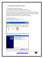
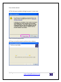
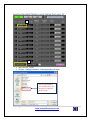
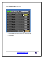
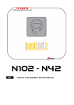
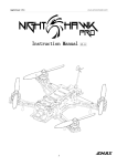
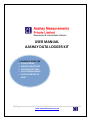
USER MANUAL
AASHAY DATA LOGGER KIT
A COMPLETE GUIDE FOR
• DATA LOGGING
• SENSOR CINNECTIONS
• SOFTWARE SETTINGS
• DATA DOWNLOADING
• DATA EXPORTING TO
EXCEL
1|Page
Aashay Data Logger Kit User Manual
www.aashaymeasurements.com
Contents
1. Flow Chart …………………………………………………………………………………………………………..3
2. Hardware Check List …………………………………………………………………………………………….5
3. Software Installation Guide……………………………………………………………………….………….7
4. Communication ……………………………………………………………………………………….…………12
5.
Capture Setting………………………………………………………………………………………..…………15
6.
Pressure Setting………………………………………………………………………………………………….17
7. Temperature Setting…………………………………………………………………………………………… 19
8. RPM Setting……………………………………………………………………………………………………......20
9. Sampling Rate Setting…………………………………………………………………………………………..22
10. Pressure Cable Connection Procedures …………………………………………..……………………26
11. Thermocouples Cable Connection Procedures …………………………………..………………..27
12. RPM Cable Connection Procedures ………………………................................................28
13. Battery Cable Connection Procedures………………………………………………….………………29
14. Status Indicator Lights………………………………………………………………………………………….30
15. Start Data Logging………………………………………………………………………………………………..31
16. Stop Data Logging………………………………………………………………………………………………..32
17. Download Data…………………………………………………………………………………………………….33
18. Covert GBD data file to CSV file Procedure……………………………………………….………….35
19. Keypad operation………………………………………………………………………………………………..37
20. Download / Copy Data Using Pen Drive. ………………………………………………….…………..38
21. Technical Support …………………………………………………………………………………….………….39
2|Page
Aashay Data Logger Kit User Manual
www.aashaymeasurements.com
1. Flow Chart : Simple Operating Procedure
Mount Thermocouples, Pressure Transmitters
and MPU on Respective locations on Engine
Connect Cables of Pressure Transmitters, Thermocouples and MPU Sensor to
the respective ports of the Data Logger. (Refer page no. 26, 27 &, 28)
Connect Battery Cable to the Vehicle Battery 12 or 24VDC.
(Do not connect AC power to data logger) (Refer page no.29)
Turn on Front Switch on the Data Logger.
To power up Main Instrument turn on Switch which is located on top
(Right side of the Keypad) (Refer page no.30)
NO
Check Setting of
Pressure
channels
Verify: Pressure
Readings are correct?
(Refer Page
No.17)
YES
NO
Verify: Temperature
Readings are correct?
Check Setting
of Temp
channels
(Refer Page
No.19)
YES
3|Page
Aashay Data Logger Kit User Manual
www.aashaymeasurements.com
YES
Verify: RPM
Readings are correct?
NO
Check Setting
of RPM
channels
(Refer Page
No.20)
YES
Start Recording by Pressing Start Stop Key on Keypad and Press Enter
Memory Recording will Start Flashing on display
(Refer Page No. 31)
Run the Engine and Record the Data for you required time duration.
Confirm the Memory Recording is flashing.
Stop Recording by Pressing Start Stop Key on Keypad and Press Enter
Free Running will Start Flashing on display
(Refer Page No. 32)
Download Data File
(Refer Page No. 33)
Export Data File to Excel
(Refer Page No. 35)
4|Page
Aashay Data Logger Kit User Manual
www.aashaymeasurements.com
2. Hardware Check List
1
2
3
4
5
10
8
6
7
5|Page
Aashay Data Logger Kit User Manual
www.aashaymeasurements.com
9
Hardware Check List
Sr. No.
Description
1 GL220 Data Logger
2 Pressure Transmitter
Range
2.1 0 to 25 Bar
2.2 0 to 25 Bar
2.3 0 to 4 Bar
2.4 0 to 4 Bar
Qty
1 No.
1 No.
1 No.
1 No.
1 No.
3 Thermocouples
6 Nos.
4
4 Nos.
Cable of Pressure
5 K type compensating cables with Heavy duty Connector
6 Nos.
6 RPM cable
1 No.
7 Battery Cable
1 No.
8 USB Cable
1 No.
9 Software CD
1 No.
10 Manual
6|Page
1 No.
Aashay Data Logger Kit User Manual
www.aashaymeasurements.com
3. Software Installation Guide
3.1. Installing the GL220 Application Software
This chapter describes how to install the application software.
(1) Insert the User's Guide CD-ROM provided into the PC's CD-ROM drive.
(2) Click the Taskbar's Start button, and then click the Run... icon to open the "Run" window.
(3) Enter the CD-ROM drive name and \English\English\GL220-820\Setup.exe as the name of
the file you wish to open. If the disk is in drive D, for example, enter "D\English\GL220_820APS\Setup.exe" in the box and then click "OK" to launch the installer.
(4) Follow the instructions on the screen to continue with the installation.
3.2Installing the USB driver
(1) Start D: \USB Driver\USB Driver\Setup.exe.
(Double click the Setup or Setup.exe.)
(2) Device Driver Installation Wizard starts.
7|Page
Aashay Data Logger Kit User Manual
www.aashaymeasurements.com
Press the Next button.
(3) The Software Installation dialog box opens in some cases.
Press Continue Anyway button.
(4) Please wait while wizard installs the driver software.
8|Page
Aashay Data Logger Kit User Manual
www.aashaymeasurements.com
(5) The installation completes.
Press Finish button to exit the Setup.
(6) Turn on the GL220 logger and wait for a while till the initialization of device is
Completed.
Connect GL220 to your PC using the USB cable.
The Found New Hardware Wizard in (7) and subsequent steps starts only at the first
Connection. (It will never appear again after the next connection of your device to your PC.)
When the USB port to be connected is changed or the USB-HUB is used, the Found New
Hardware Wizard reopens in some cases.
In that case, perform step (7) and subsequent steps.
(7) The Found New Hardware Wizard starts.
Select "No, not this time" and click the Next button.
9|Page
Aashay Data Logger Kit User Manual
www.aashaymeasurements.com
(8) Specify the installation method.
Select "Install the software automatically (Recommended)" and click the Next button.
(9) The Hardware Installation dialog box opens in some cases.
Press Continue Anyway button.
10 | P a g e
Aashay Data Logger Kit User Manual
www.aashaymeasurements.com
(10) Please wait while wizard installs the driver software.
(11) The installation completes.
Click the Finish button to exit the Found New Hardware Wizard.
3.3 Launching the Software
Click the Taskbar's "Start" button ProgramsGL220_820-APS GL220_820APS" to launch the
application software. Once the program has started up, the following screen is displayed.
11 | P a g e
Aashay Data Logger Kit User Manual
www.aashaymeasurements.com
4. Communication
Communication of Data Logger with PC:
Power up the logger GL220 Data logger & connect it to PC through USB Cable.
Open GL220 software.
Click the "Connect" in the Main screen, and the Connection screen will be displayed.
12 | P a g e
Aashay Data Logger Kit User Manual
www.aashaymeasurements.com
Loading Standard (Ready to use) Setting from your PC
1
2
1. Select Device : GL220
2. Click on : Loading Conditions. Following window will open.
This file is provided to
you in Aashay CD or you
may ask us to get this
file by e-mail.
13 | P a g e
Aashay Data Logger Kit User Manual
www.aashaymeasurements.com
Select: Setting GL220.chg and click on OK.
3
4
3) Click on Connect. After clicking Devices Status will displayed “OK”.
4) Click on Close.
14 | P a g e
Aashay Data Logger Kit User Manual
www.aashaymeasurements.com
5. Capture Settings
Settings such as the Channel Setup, Sampling Interval are made at this screen.
Click the "Capture Settings" button Open New windows.
15 | P a g e
Aashay Data Logger Kit User Manual
www.aashaymeasurements.com
•
AMP Setting:
16 | P a g e
Aashay Data Logger Kit User Manual
www.aashaymeasurements.com
6. Pressure Setting
- CH No. 1 to CH No. 4 are connected to Pressure inputs P1 to P4 respectively, so
particularly we can configure CH1 to CH4 for Pressure inputs.
Note: These channels are already set while supplying the instrument, so you no need to set /
configure the channels.
In any case if settings are disturbed, you may retrieve the original settings by referring :
Loading standard Set-up procedure on page no. 13 & 14.
To set the Pressure channel to CH1 to CH4, refer following procedure.
Select Input “DC”.
Select input Range “1-5 V”
17 | P a g e
Aashay Data Logger Kit User Manual
www.aashaymeasurements.com
Click the scaling “on” this will open Scale Setting Window.
For e.g. for Pressure Transmitter Range: 0-25 Bar scaling will be as follows,
Device
Scaling
Upper 5
Upper 25
Lower 1
Lower 0
Unit of
V
as
Bar
Then click OK
Pressure channel Setting:
Sr. No
1
0 - 25 Bar
Sensor Type
Description
P1
Channel name
Pressure_1
2
3
4
0 - 25 Bar
0 – 4 Bar
0 – 4 Bar
P2
P3
P4
Pressue_2
Pressure_3
Pressure_4
18 | P a g e
Aashay Data Logger Kit User Manual
www.aashaymeasurements.com
7. Temperature Channel Setting
CH5 to CH10 are connected to Temperature Channels T1 to T6 respectively.
We have supplied 6 nos. of Temperature Sensors (K type Thermocouples) along with
this kit.
Note: These channels are already set while supplying the instrument, so you no need to set /
configure the channels.
In any case if settings are disturbed, you may retrieve the original settings by referring:
Loading standard Set-up procedure on page no. 13 & 14.
To Set Temperature Channel at CH5 to CH10, refer following procedure.
Select Input “TEMP”.
Select input Range “TC-K”
19 | P a g e
Aashay Data Logger Kit User Manual
www.aashaymeasurements.com
8. RPM Setting
Logic/ Pulse channel 1 and 2 are connected to RPM Channels, RPM1 to RPM2 respectively.
Before doing RPM setting you should know the No. of teeth of the wheel of engine.
Logic / Pulse Settings
1
2
3
1. Select Pulse at Logic Pulse Setting
2. Select Input “Inst”.
3. Select input Range “5kC”
4. Click the scaling “on” this will open Scale Setting Window.
20 | P a g e
Aashay Data Logger Kit User Manual
www.aashaymeasurements.com
4
Then click add / Edit scaling, in this window we have to scale Frequency into RPM.
For e.g. for engine having Number of teeth 142
Formula:
RPM = Frequency x 60 / No. of teeth
For Frequency = 1000 & no. of teeth = 142
RPM = 1000 x 60 / 142
RPM = 422.53.
Then click OK
21 | P a g e
Aashay Data Logger Kit User Manual
www.aashaymeasurements.com
9. Sampling Rate Settings
Select sampling rate
drop down menu
To Select Input “sampling Interval”.
22 | P a g e
Aashay Data Logger Kit User Manual
www.aashaymeasurements.com
Standard set up window
Standard Set up window of all channels is as follows:
1 Click Apply &
2
2 OK
23 | P a g e
Aashay Data Logger Kit User Manual
www.aashaymeasurements.com
1
Saving Setting on your PC
1
\
1) Click on “connect” Saving screen will be displayed
2
24 | P a g e
Aashay Data Logger Kit User Manual
www.aashaymeasurements.com
2) Click on : Saving Conditions. Following window will open.
Save the changed setting file
named: Setting GL220
in user PC for future use.
(While connecting next time
you need to load this file
from loading conditions.)
3) Save Setting and click on OK.
25 | P a g e
Aashay Data Logger Kit User Manual
www.aashaymeasurements.com
10. Pressure Cable Connection Procedures
1
2
3
26 | P a g e
1) Mount the pressure Transmitter on
Engine. We have provided 1/8 inch
NPT fitting along with Temperature
Sensor.
2) Connect Pressure Cable to Pressure
Transmitter.
3) Connect the pressure cable to the
pressure connector port on data
logger. (see Pic. 3)
(Match the Pressure Tranmitter No.
e.g. P1 to the P1 port data logger. and
same annotations are given on both
ends of the Temperature Cable )
Aashay Data Logger Kit User Manual
www.aashaymeasurements.com
11. Thermocouple Cable Connection Procedures
2
3
1
(1) Mount the Thermocouple on Engine. We have provided 1/8 inch NPT fitting along
with Temperature Sensor (see Pic. 1)
(2) connect the thermocouple sensor to extension cable (see Pic. 2)
(3) Connect the thermocouple cable to the Thermocouple port on data logger. (see
Pic. 3)
(Match the Thermocouple No. e.g. T1 to the T1 port data logger and same annotations
are given on both ends of the Temperature Cable )
27 | P a g e
Aashay Data Logger Kit User Manual
www.aashaymeasurements.com
12. RPM Cable Connection Procedures
3
1
2
1) Mount the MPU on Engine.
2) connect the MPU output signal to extension cable (see Pic. 1)
3) Connect the MPU cable to the RPM port on data logger. (see Pic. 2)
28 | P a g e
Aashay Data Logger Kit User Manual
www.aashaymeasurements.com
13. Battery Cable Connection Procedures
1
Connect to Positive Terminal of Battery
Connect to Negative Terminal of Battery
Turn on the Switch
2
Connect battery Supply DC
12 to 24 VDC
(1) Connect Battery Cable to the DC Battery 12 or 24VDC.
Ensure that the Red Clamp is connected to + ve terminal of battery and Black Clamp is
connected to - ve terminal of battery (see pic.1)
And also ensure that the DC Battery is fully charged before use.
(Do not connect AC power)
(2) Connect the Battery cable to the Battery port 12-24 VDC on data logger. (see Pic. 2)
29 | P a g e
Aashay Data Logger Kit User Manual
www.aashaymeasurements.com
14. Status Indicator Lights
LED ON
LED ON
2
1
Turn on the Power supply
Turn on the Power Supply to Data logger
(1) Turn ON the switch to give voltage Excitation to pressure sensor, RPM sensor condition &
charging the Data logger. Check the status the Interface LEN is ON or OFF.
If Led is not glowing, check the Battery voltage. It should be 12 to 24 Volts require. (see
pic.1)
(2) Turn on the switch to turn on Data logger Display. LED or Display will ON. (see pic.2)
30 | P a g e
Aashay Data Logger Kit User Manual
www.aashaymeasurements.com
15. Start Data Logging
For Starting data Recording:
Press the START/STOP key
- Following message will be prompt on display of
data logger
Press the ENTER key to start data
capture
Note : It is not mandatory to connect data logger
to Computer while recording the data.
Keypad on data logger will be deactivated when
connected to computer.
Data Logging Confirmation: Memory “Recording” and Rec should flash
Online Monitoring of the Readings
Online Monitoring of the Graph
Name and path of the data file
12.1 : Send Data Logger with Engine / Generator for Data Logging :
After getting confirmation of all above things, you may start the Engine / Gensets and record the data
for your required time durations.
31 | P a g e
Aashay Data Logger Kit User Manual
www.aashaymeasurements.com
Note : While Recording please take care of following things:
-
Do not disturb / Remove the Battery connection.
-
Do not turn off the data logger.
-
Please check periodically that : Memory Recording is flashing.
16. Stop Data Logging
After completion of the data logging, stop the data capture.
Press the START/STOP key
- Following message will be prompt on display of
data logger
Press the ENTER key to Stop data
Capture.
Data capture ends, and the Data
Logger goes into the Free Running status.
Now you may download data by referring procedure on page no.33.
32 | P a g e
Aashay Data Logger Kit User Manual
www.aashaymeasurements.com
17. Download Data
-
For Downloading the datafile you need to connect the data logger to PC. For
connection procedure please refer the page no.
After connecting the data logger.
Click on File
Click on “Open Data”
After clicking on “Open Data” , following Window of Data files selection will open.
33 | P a g e
Aashay Data Logger Kit User Manual
www.aashaymeasurements.com
Select Data file path : Device1 MEM 120813 (folder name in format of
To Select Device 1
Select Data file : 120813_174320 (File name in format of YYMMDD_HHMMSS
Click this button to select the file (display the file).
Click t on “Select File” this will open the Data File in following Window.
Note : You can not download data while Data Logger is in Memory Recording Mode.
34 | P a g e
Aashay Data Logger Kit User Manual
www.aashaymeasurements.com
18. Covert GBD data file to CSV (excel) file Procedure
GBD (binary data) files to be converted in an Excel (CSV) format files.
Click on “Convert then Save” button this will be open window.
To Select CSV Format
Data file path
Click on save
After clicking on “Save” button. Excel Data File will open.
35 | P a g e
Aashay Data Logger Kit User Manual
www.aashaymeasurements.com
Data File in Excel Format.
You may save this excel file for your further analysis.
36 | P a g e
Aashay Data Logger Kit User Manual
www.aashaymeasurements.com
19. Keypad operation
19.1 Setting menu
When you press the MENU key
during Free Running, the
following menu screens appear.
The menu screens are classified
by the tab for each setting item.
Note: Keys is enabling when data
logger is not connected in PC
communication.
1) Amp Setting
This menu is used to specify input signal-related settings.
<Analog settings>
<Logic Pulse settings>
37 | P a g e
Aashay Data Logger Kit User Manual
www.aashaymeasurements.com
20. Download / Copy data by using “PEN Drive.”
Data Download procedure
Single
arrow
Double
arrow
Hook the Pen drive in USB-PENDRIVE Port.
Press “FILE” key in Keyboard.
“ Enter” key file operation:
Will be open Disc Operation.
Press right single arrow Key.
Select folder by using double arrow key.
(Copy file / folder)
7) Enter Key.
(Select file(s) to copy)
8) Enter Key
(Selected file is blue)
9) By using double arrow key to select USB
path.
(Select copy dest. & Execute)
10) Enter
11) Ok … press Quit key.
12) Remove pen drive.
1)
2)
3)
4)
5)
6)
Hook the PENDRIVE
38 | P a g e
Aashay Data Logger Kit User Manual
www.aashaymeasurements.com
21 Technical Support
Important Instructions
It is recommended that one person from Area office will be
responsible for the use and contains of the Data Logger kit while it is
being used, transported or stored.
Data Logger Kit will be used by the Persons Trained by the supplier.
Proper packaging should be done while it is being transported.
Before and after the data acquisition trial the logger, sensors, cables &
other parts in the kit should be checked as per the checklist provided
with the kit.
In each month report related to its use, important data files, contents,
missing parts etc. should be sent to H. O. Pune.
In case of any problem about the use of equipment or any will be
communicated to Aashay Measurements Pvt. Ltd. Pune.
Users should not unnecessarily open its interface unit and its wiring
etc.
Software master CDs should be maintained separately and can be
loaded at multiple locations.
12V, 7amp hr Sealed lead acid battery should be kept at offices. The
battery should be dedicated for Data Logger.
Direct Technical Support Helpline numbers are:
9423241542, 02024376819, 9561609564.
Tele/Fax: 020-24376819 Mobile: 09423241542, 09561609564.
Email: [email protected]
www.aashaymeasurements.com
39 | P a g e
Aashay Data Logger Kit User Manual
www.aashaymeasurements.com