1
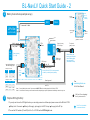
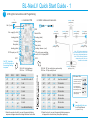
BL-NavLV Quick Start Guide - 1
1
1
LED Lights Connections and Programming
T
connector
x 1 controller PCB
x 8 LEDs / cables and connectors
Landing - white
(constant on)
-
Bat. (1s~6s)
+
USB
Ext. supply (5v~24v)
Landing (white)
Nav (green)
Nav (white)
Nav (white)
Landing (white)
SW 2
SW 3
off
off
off
off
off
off
Nav - green
(constant on)
Nav - white
(blinking on / off)
Note : LED lights can be doubled
up to a maximum of 16 LEDs in total
with no loss of brightness (No more
than 2 LEDs per output otherwise
damage may result). See user
manual for more details
RC o/p for servo switching
and 5v, 3A / 4A (burst) BEC
1.
.
4
4.
.
1
SW 4 off : High brightness
SW 4 on : ULTRA bright
SW 1
Landing - white
(constant on)
Nav - white
(blinking on / off)
Landing / beacon - (red)
RC Rx input (on / off)
Set DIP 1 switches
to all ON to check out
the warning flashing
sequence
Landing - white
(constant on)
Landing (white)
Nav (red)
DIP 1
Nav - red
(constant on)
Status LEDs
Meaning
DIP 2
SW 4 off : RC o/p and i/p (max pulse active)
SW 4 on : RC o/p and i/p invert
Landing - red (beacon)
(blinking on / off)
Meaning
SW 1
SW 2
SW 3
Low Bat Volt mode off
off
off
off
Low time mode off
LiPo below safe (flashing)
LiPo below v. low (on)
on
1 cell
off
off
on
10 minutes
System ok (flashing)
on
off
2 cells
off
on
off
15 minutes
off
on
on
3 cells
off
on
on
20 minutes
Volt mode (flash on)
Time mode (flash off)
Both (flashing on / off)
on
off
off
4 cells
on
off
off
30 minutes
on
off
on
5 cells
on
off
on
40 minutes
on
on
off
6 cells
on
on
off
50 minutes
on
on
on
Low Bat test flashing
on
on
on
60 minutes
PCB status LEDs
Ultra bright (const. on)
High bright (off)
See
www.bluelight-tech.com
for full User Manual
(+ optional PC tool)
1. Select the number of cells if you want the warning flashing
sequence to happen when the voltage falls below a safe level
2. Select the time if you want the warning flashing sequence
to happen after a certain time (after system power up)
BL-NavLV Quick Start Guide - 2
2
Battery Connections (example set-up)
1
USB
(set-up
program
available)
Must be
ground
ESC
Motor
T connector Y cable
LiPo Bat
Must be
ground
(up to 6 cells)
Must be
ground
Arrows show must be
ground, if connected
black - ground
Bat.
(e.g.
9v)
Gear up / or any
RC Rx output
LiPo
Check
red - power
Rx
Back-up battery
(7v ~ 24v)
To Bat or any
RC Rx input
BEC output
High
On
On
Low
On
Off
D1
On for
ULTRA
bright
mode
4
3
On
On
Mid
Off
Off
Low
On
Off
black - ground
4
If main LiPo fails, RC Rx / servos operated
via the 9v (or similar) back-up battery
D2
On to
invert
switch
3 way RC Tx switch
Sw
Landg.
Nav.
High
Cable to deploy the
landing gear coincident
with the landing lights
being switched on
(See tables to the left)
red - 5v
Input switches between
Nav and landing lights
2 way RC Tx switch
Sw
Landg.
Nav.
To optional
gear up servo
black - ground
red - 5v
See
www.bluelight-tech.com
for full User Manual
Note 1 : Ground (black) wires on the 3 pin connectors MUST BE on the outside edges of the BL-NavLV PCB
Note 2 : You will need to make your own connection cables, depending on specific requirements and battery connectors you use
PCB Red LED on or flashing?
Don’t fly the attached LiPo !
1
Simple LED Lights Only
1. If you only want to use the LED lights function you can simply connect one of these input power sources to the BL-NavLV PCB:
Battery to the T connector
Battery to Ext supply
5v supply to the RC Rx input
5v supply to the RC o/p
2. Then set the DIP switches (D1 and D2) to ALL off, or D1 SW4 on for ULTRA bright mode.
Free PC tool is available
for advanced features