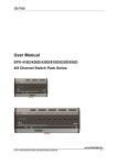
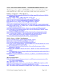
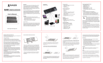
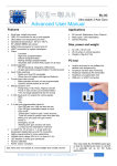
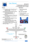
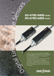
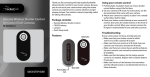
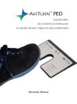
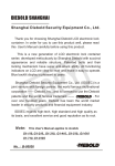
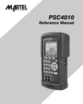
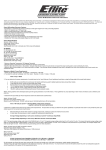
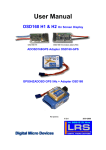
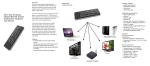
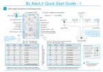
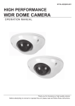
1
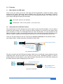
_______________________________________________________________________________________________________ 70A+ Smart Switch BL-Smart70SW User Manual High Current LiPO Battery Arming Switch ____________________________________ Solid State – High Reliability Ultra Low On Resistance / Low Temperature _______________________________________________________________________________________________________ Features Applications LiPo 2s to 8s (6.6V min to 34V max) Smooth application of power o No pitting of connectors (adding resistance / voltage loss) No arching as connection is made o No stress to ESC with glitchy hand connecting Continuous Operation up to 70 A o 5 sec bursts up to 140 A (In-rush up to 2,000 A) Simple Toggle switch on / off Auto Switch disable (off) / cut-off in case of aircraft crash o Circuit break interface External Circuit input (Electronic on/off): o External device can switch on / off as required o Can be used for high power strobe lights LED Indications o Switch is on (blue) o Output is active (green). Note, the output can be deactivated with an external circuit or via the aircraft crash auto-disable feature Ultra low resistance when switched on o 0.00065 Ω o Cool operation Little Power Loss when switched on o Typically 8s LiPo @ 100A will lose 0.2% (200 mA) Miniscule power used when switched off o Typically 2μA (0.002 mA) for the switch o LEDs will normally be off Very Small Voltage drop o Typically 0.07 V at 100 A current drawn Can switch inductive loads Operational temperature: -30 0C to +80 0C RoHS, “green” compliant UAV / UAS / FPV / RC Airplane / Heli Multi-copter and hybrid Aircraft General Robotics Safety Auto cut-out, in case of accident (Or power off via servo connection) No connector pitting and RC electronics stress Isolate the aircraft motor(s) from battery as soon as it’s back within reach External circuit can auto cut the power in the event of a major aircraft problem No micro processor, no software. All solid state design for high reliability Size, power and weight 63 x 33 mm unit (2.5 x 1.3 inch) (Not incl. mounting screw tabs) 1 W power requirement @ 40A Weight is 29g (1.0 Oz) with no connectors State of the art Heavy Copper PCB design Dual Battery Connection Options 1 x BL-Smart70SW with second LiPo in Series o Any x2 LiPo batteries of same C rating (No need battery voltages to be matched) o Output up to 68V (16s) and 70 A continuous (140A bursts) 2 x BL-Smart70SW in Parallel o Balanced x2 LiPo batteries (Batteries must be well matched) o Reduced voltage drop (0.1V @ 300A) o Redundant battery in case one fails (external electronics can switch off faulty battery) o Output up to 34V (8s) and 140 A continuous (280A bursts) n x BL-Smart70SW of course also possible… RCgroups.com : “I wouldn't think of flying a plane without a switch--too easy to have screw up and get hurt.” See more details at: www.bluelight-tech.com/BL-Smart70SW.htm Bluelight Technologies Co. Ltd. | BL-Smart70SW User Manual V1.1 1 of 11 1.0 Features 1.1 Main Switch and LED lights There is only one switch on the unit. This allows the BL-Smart70SW to switch the battery voltage through to the output. When this switch is ON the blue LED light will be illuminated. If there is nothing else preventing the voltage and current from being passed through to the outputs then the green output LED light will also be illuminated. BLUE LED : Switch is ON / Enabled GREEN LED : Power is being Output – you’re good to go! 1.2 Safety Auto Cut-off Switch Feature The external auto cut-off is designed to cut the output in case of aircraft accident, or if you wish to isolate the entire system via a servo. During a serious accident it is common for the heavy items such as battery or motor to be dislodged from the main aircraft body. It is also possible for the battery and motor to still be connected to each other due to the strong wire and connections used. Hence if a cable is attached to such objects it will act at a cut out for the switch as shown here. There is a two pin header on the unit. The two pins must be connected for the switch to allow any voltage output. A cable should be connected as shown here Connect internal wires Secure around the motor or aircraft bulkhead or battery E.g. bulk head Connection Plug the connector into the PCB two pin header. Make sure to electrically connect together the two conducting wires. Secure the cable to the motor or motor mount / bulkhead or battery. In case of accident and the aircraft breaks up the cable will likely disconnect from the PCB thus shutting off the switch and any output voltage going to the motor. Connect internal wires RC Tx switch / Servo can be set up to cut total System power E.g. Servo Connection Bluelight Technologies Co. Ltd. | BL-Smart70SW User Manual V1.1 2 of 11 1.3 External (Electronic) Switch Activation If you have some external electronics that you would like to take charge of switching the BLSmart70SW on /off then a simple two way cable can connect to this two pin header interface. One side is Vcc the other is Gnd. Vcc can be anything from 3.3v to 34v. Any such voltage on this interface will shut off the switch. Restoring ground, or no connection to this interface will allow the switch to again give an output. For example an RC Rx can activate a relay switch (such as the PicoSwitch, or Turnigy Receiver Controlled Switch) on this interface. The external switch input can also accept high frequency switching pulses (up to around 3MHz, minimum pulse width 0.3μs) so can easily switch high current lighting systems. Low signal (0 ~ 1v) High signal (3.3 ~ 34v) : On : Off 2.0 Installation 2.1 Main On / Off Switch A switch is provided with the BL-Smart70SW, however it is perfectly acceptable to install any toggle switch you prefer. The switch will use very little current (15mA). You may even wish to use your own switch and also include a small LED. You can do this too by just wiring an LED in series with the switch (positive side of the switch to the positive side of the LED). There is no need to include a series resistor since this is already on the main BL-Smart70SW module. BL-Smart70SW Can be anything from 1s to 8s Bat Load Bat + Load + LiPo 1 (8s) Auto cut-out switch ESC Equivalent Circuit Toggle switch B+ L+ B- L- ESC / Load Example simple 8s / 70 A continuous system In the above single LiPo connection the low power toggle switch simply completes the circuit when activated. Bluelight Technologies Co. Ltd. | BL-Smart70SW User Manual V1.1 3 of 11 2.2 Series Connection of x1 BL-Smart70SW with a second LiPo battery More batteries / higher voltages can be accommodated by connecting a second battery in series with the BL-Smart70SW. The batteries don’t need to be the same voltage. Can be anything from 1s to 8s LiPo 2 (8s) BL-Smart70SW Can be anything from 1s to 8s Bat Load Bat + Load + LiPo 1 (8s) ESC 1 Equivalent Circuit 2 B+ L+ B- L- Toggle switch ESC / Load Example dual battery (series) 16s / 70 A continuous system As can be seen in the example above. The BL-Smart70SW switch is simply in the circuit and switches the entire 16s system on / off. Note that the entire current will flow through both batteries and so they must be matched in terms of C rating, but not in terms of voltage. Make sure to connect up the BL_Smart70SW as shown in the diagrams above. There is an alternative way to connect up in series which should not be done. (I.e. Bat+ must connect to the first LiPo battery +). Bluelight Technologies Co. Ltd. | BL-Smart70SW User Manual V1.1 4 of 11 2.3 Parallel Connection of x2 BL-Smart70SW’s More current with lower voltage drop can be accommodated by connecting a second battery and switch in parallel. In this case it is important for the LiPO batteries to be well matched. Can be anything from 1s to 8s LiPo 2 (8s) LiPo 1 (8s) Bat Load Bat + Load + B Bat Load Bat + Load + A BL-Smart70SW BL-Smart70SW Can be anything from 1s to 8s Toggle switch (DPDT) ESC ESC running at 16s (59.2V) SW Equivalent Circuit 1 2 B+ B+ A L+ ESC / Load L+ B- B- B L- L- Example dual battery (parallel) 8s2p / 140 A continuous system In this set up a two pole toggle switch should be used to ensure the switches are set together. If one is set before the other then all the current will be drawn from only the one battery to start with. (DPDT) Note that it’s also possible to have an external circuit apply, for example, 5v (up to 34v) to the external circuit input and then set both BL-Smart70SW units to 0v simultaneously to ensure exactly synchronous operation. However it should not be necessary to be so accurate with this. If using the auto cut out switch, this should be organized to pull out of both switches in the case of an aircraft accident. Bluelight Technologies Co. Ltd. | BL-Smart70SW User Manual V1.1 5 of 11 2.4 Connection to Inductive Loads Firstly, what is an inductive load? An inductive load is one in which there is some type of electro-magnetic storage of energy. Brushless motors, for example, generate fairly strong magnetic fields in their windings when current is passed through them. If then the motor is switched off, the magnetic fields will collapse. (A high voltage potential is created to try to maintain the current). This will be fast but it will take a finite time. The result is that a high voltage is produced and the energy stored inside the magnetic fields will generate a current. The high voltage is in the opposite direction to the voltage applied to the motor in the first place. Hence this high reverse voltage and current need to be blocked from the motor drive electronics. The BL-SmartSW has two levels of protection to achieve this. Hence if you wish to connect the BL-SmartSW to the actual motor (BEC output) rather than the BEC input, this will be no problem. 2.5 In-rush Current ESC units have large capacitors which need charging on first power connection. (This is why some arching / sparks occur when first connecting up a battery to one or more ESC units. Using the BLSmart70SW this is avoided). This first connection therefore draws a great deal of current to charge up the capacitor(s). The BL-Smart70SW can easily handle an in-rush current of 2,000A with no problems. It can even go up to 3,000A for a very brief period of time without damaging the switch. 3.0 Operation 3.1 Normal Operation (Mechanical switch) The switch is simple to use; just switch on to allow the battery to connect to your aircraft ESC units and electronics and off to disconnect. 3.1 Electronic Operation If switching on and off using the electronic switch interface simply input a signal (DC or at frequency less than or equal to 3MHz) to the Electronic input switch (red is signal, black is ground). Low signal (0 ~ 1v) High signal (3.3 ~ 34v) : On : Off Note: When not flying you should ALWAYS disconnect your battery from the switch. Although in the off state very little current is drawn, over a long period of time it will drain your LiPo battery. LiPo batteries should be stored with a certain level of charge inside them to avoid damage. Bluelight Technologies Co. Ltd. | BL-Smart70SW User Manual V1.1 6 of 11 4.0 Detailed Specification (All charts by calculation) 4.1 Very Low Power and Voltage Loss % current 0.80% Power Loss (W) Watts 10 0.70% 9 0.60% 8 0.50% 7 @ 11V 6 0.40% @15V 5 @30V 0.30% 4 3 0.20% 2 0.10% 1 Amps 0 0 20 40 60 80 100 Amps 0.00% 120 0 20 40 60 80 100 120 Fig 2. % current lost as % of total current drawn Fig 1. Power loss in switch as a function of total current drawn Vdrop V 0.09 0.08 0.07 0.06 0.05 0.04 0.03 0.02 0.01 Amps 0.00 0 20 40 60 80 100 120 Fig 3. Voltage drop as a function of current drawn Fig 1 shows the power loss as a function of the power output to the motor. A high current of 100 Amps results in a 6.5 Watt power loss in the switch. Hence, as shown in fig 2, if running a 29.6V, 8s LiPo battery at 100 Amps, this will result in a loss of only 0.22%, i.e. a loss of only 220 mA. At a much lower power output of say 50A the loss will be 0.11% or 55 mA. Fig 3 shows the voltage drop as a result of the switch alone. Any externally connected low voltage detector triggering on a pre-set low voltage will need to be more accurately set by taking into consideration the switch. However the switch will only cause a very small drop in voltage as can be Bluelight Technologies Co. Ltd. | BL-Smart70SW User Manual V1.1 7 of 11 seen. For example running at 100 Amps (irrespective of the number of cells used), the drop is only 0.07V. For comparison consider a 12 AWG cable. This will have a resistance of around 0.001 Ohm per foot with a temperature rise of approx. 40 degrees when carrying around 100 A of current. Hence, 1 foot length of this cable would give rise to a power loss of some 10W, or, at 29.6V, a current loss of some 340mA. And a voltage drop of 0.1V. 4.2 Current and Temperature It is also important to have the switch not run too hot due to the possible confined space inside an RC aircraft or UAV. The issues are related to safety of the aircraft and also the silicon switching device (FET) inside the switch. Fig 4 shows the temperature of the unit vs continuous current drawn. ºC 100 90 80 70 Finger touch limit 60 50 40 Amps 30 20 40 60 80 100 120 Fig 4. BL-Smart70SW temperature as a function of continuous current drawn (ambient at 30 ºC) Acceptable finger touch temperature is at 65 ºC (149 ºF) maximum as shown. Bluelight Technologies Co. Ltd. | BL-Smart70SW User Manual V1.1 8 of 11 Fig 5 shows that even if the ambient temperature the switch is operating in is 80 ºC and a continuous current of 130A is being drawn, the BL-Smart70SW is still within the safety margin (175 ºC) of the FET device. Hence we specify the switch to only operate at such high currents in few second bursts. Normal operating range should be kept at or under 70A unless the switch has good airflow. In any case it’s always advisable to mount the switch in such a location on the aircraft so it can get good cooling airflow ºC 250 200 150 @80C @50C @30C 100 50 Amps 0 0 20 40 60 80 100 120 140 160 Fig 5. FET junction temperature as a function of continuous current drawn (BL-Smart70SW) Operating the BL-Smart70SW at a continuous current of 130A within an ambient environment of 80 ºC and no airflow will likely damage the unit PCB. It will get very hot; approaching 170 ºC (338 ºF), and so should be avoided unless very good air flow cooling is provided. Operating the BL-Smart70SW at a continuous current of 160A within an ambient environment of 30 ºC and no airflow will likely damage the unit PCB. The temperatures will approach 170 ºC (338 ºF). Very good air cooling would need to be provided to operate continuously at this level of current. Bluelight Technologies Co. Ltd. | BL-Smart70SW User Manual V1.1 9 of 11 4.3 Dimensions Very small unit size: [2.48"] [2.87"] [1.02"] [1.3"] BL-Smart70SW / BL_Smart100SW [0.28"] [2.64"] Supplied toggle switch (Main switch) for mounting on the aircraft frame: Bluelight Technologies Co. Ltd. | BL-Smart70SW User Manual V1.1 10 of 11 5.0 Ordering Information Comparison of the two versions available: Parameter BL-Smart70SW BL-Smart100SW Max. continuous current (no airflow / cooling) Max. burst current (for a few seconds) Case touch temperature in 30ºC (86 ºF) ambient environment with 50 A continuous current drawn Dimensions Extrusion Heat Sink Weight 70A 140A 43.2 ºC (109.8 ºF ) 100A 200A 38.6 ºC (101.5 ºF ) 73 x 33 x 15 mm No 25g (0.9 Oz) 73 x 33 x 25 mm Yes 28g (1.0 Oz) Note1: If not explicitly stated, all other parameters and features are identical Note2: Always use Bluelight Technologies’ original products available from Bluelight Technologies directly, or its official distributors. Bluelight Technologies always use original silicon devices from the original manufacturers to guarantee quality, performance and durability. This is particularly important for power devices. ________________________________________ See http://www.bluelight-tech.com/BL-Smart70SW.htm for more information Contact: [email protected] All content copyright © 2014 Bluelight Technologies Co. Ltd. 199 / 206 Moo3, Soi Tha It, Rattanathibeth Road, Muangnonthaburi, Nonthaburi 11000. Bluelight Technologies Co. Ltd. | BL-Smart70SW User Manual V1.1 11 of 11