1
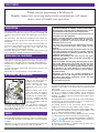
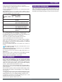
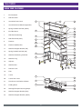
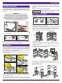
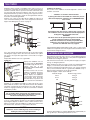
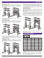
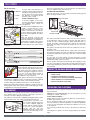
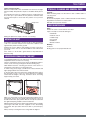
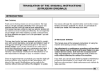
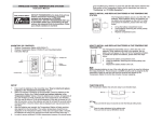
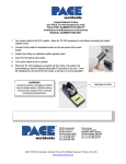
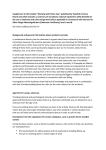
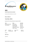
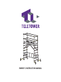
OWNER’S INSTRUCTION MANUAL
TELETOWER
INDEX
DESCRIPTION
2
UNPACKING THE TELETOWER
2
ATTACHING THE STABILISERS
2
SAFETY
2
RISK ASSESSMENT
3
WORK AREA PREPARATION
3
KNOW YOUR TELETOWER
4
LOCKING MECHANISMS
5
GUARDRAILS
5
SETTING UP THE TOWER
5
PLATFORM HEIGHT SELECTION
6
FITTING THE PLATFORM
7
TOE BOARDS
8
CHECKS TO BE MADE BEFORE ACCESS
8
ACCESSING THE PLATFORM
8
MOVING THE UNIT
9
LOWERING/DISMANTLING THE UNIT
9
STORAGE, CLEANING AND GENERAL CARE
9
USER MAINTENANCE
9
SPECIFICATIONS
10
WARRANTY
11
1
TELETOWER
“Thank you for purchasing a TeleTower®
Regular inspection, servicing and periodic maintenance will ensure
many years of trouble free operation.”
DESCRIPTION
EUROPEAN WORK AT HEIGHT REGULATIONS 2005
New legislation came into effect in 2005 that places certain
responsibilities on Employers and/or duty holders.
You must ensure that only trained competent persons are
permitted to use the equipment.
Working at height should be avoided whenever possible.
Where it is unavoidable, you must take all necessary
measures to prevent a fall and to ensure the safest
method of access is used.
You must plan and organise the work before it begins,
carry out a full risk assessment and be guides by your
findings.
Take into account the height you need to reach, the task
you need to perform and how long it will take. Take into
consideration weather conditions, ground traffic and the
conditions of the work area.
Whatever your findings, you must only use the safest
equipment available, where reasonably practicable, to
carry out your task.
Light work (where any item being carried by the user does
not exceed 10KG) at low level, which will take very little
time (no longer than 30 minutes in one place), may only
require a set of steps or a leaning ladder. However, where
the duration is of a long period or at great height or
requires heavy work, an access tower or a scissor lift may
be more suitable.
Equipment used must be checked thoroughly for
condition before use and at regular intervals there after.
For advice and further information contact the HSE
infoline on 0845 345 0055.
Or visit www.hse.gov.uk
The TeleTower® is an easy to erect mobile scaffold tower, giving
an elevated work platform for use by one person. Raising and
lowering of the platform is quick and requires little effort from the
user.
The information and instructions included in this manual are
provided to help you get the best possible service from your
TeleTower®.
To ensure that the tower is used safely and responsibly, we
strongly recommend that these instructions are read by all users
prior to erecting and using the tower, and that the
recommendations are followed at all times.
TeleTower Ltd operate a policy of constant improvement and
reserve the right to change specifications without notice.
UNPACKING THE TELETOWER
Care must be taken not to drop the base of the tower when
unpacking, to avoid damaging the base tubes. Insertion of the
stabiliser/castor assembly may be impossible where damage to
the tubes has occurred and is not covered by the manufacturers
warranty.
Carefully unpack the TeleTower®, removing the platform and
placing to one side.
Please dispose of all packaging in a responsible manner.
ATTACHING THE STABILISERS
The TeleTower® is supplied
ready for use apart from the
stabiliser/castor assemblies.
Having unpacked the tower,
Base
remove the platform then
Tube
carefully place the tower on to its
side.
Slide the retainer catch of one
corner fully back and hold in
place as you insert a stabiliser
assembly into the end base tube.
Insert the assembly fully then
Retainer Stabiliser
release the retainer catch and
Assembly
Catch
rotate the assembly until the
catch engages.
Note that the retainer catch is the only device retaining the
assembly. When disengaged, the stabiliser/castor assembly is
free to ‘drop down’ and therefore care must be taken when
deploying the stabilisers.
The work area must be cordoned off to create a safe zone from
the general public and bystanders. The safe zone must be a
minimum of 3m radius or 1m greater than the platform height
being used.
This equipment must only be used by persons who are medically
fit to do so. If you have any medical condition, are recovering from
any medical condition or suffer from any mental or physical
disability, you MUST seek professional medical advice before
using this equipment.
This equipment must not be moved, set up, used or dismantled by
persons who are under the influence of alcohol or drugs. Do not
use this equipment if you are tired or unwell.
You MUST perform a risk assessment before using this
equipment to ensure your safety and the safety of others.
Do not overload the platform beyond the stated weight loading.
The TeleTower® is designed for use by one person ONLY + tools
up to a combined maximum weight of 150kg.
Wear the correct Personal Protective Equipment when erecting
or lowering the tower and for the task you are performing.
Wear gloves when handling this equipment.
Wear suitable clothing. Steel toecap boots
must be worn. If appropriate, wear a hard hat.
Do not wear loose jewellery or clothing that may get in the way or
become trapped in the mechanism.
SAFETY
Before using this equipment and to avoid personal injury, carefully
read and understand these instructions. If there is anything you do
not understand, DO NOT use this equipment; contact the supplier
for advice.
Make sure you are aware of all safety requirements and that this
equipment is suitable for the task you wish to undertake.
2
TELETOWER
Inform everyone in the work area of what you are doing.
Carefully inspect the TeleTower® before use, if there is any doubt
about its condition, DO NOT USE IT.
Do not use this equipment where there are overhead power lines
or similar hazards.
This equipment must not be used in wind conditions above
BEAUFORT SCALE 6 (12.5 m/s). Do be aware of the tunnel effect
caused by buildings close to each other.
WORK AREA PREPARATION
Clear and sweep the floor area, where the TeleTower® is to be
used, of obstructions and similar items. Once the tower is in the
work area, use barriers and tape to create a safe zone area. Keep
bystanders and unauthorised persons away from the work area.
BEAUFORT SCALE
BEAUFORT KNOTS
NO.
KPH
DESCRIPTION
3
7–10
13–19
Gentle breeze leaves and twigs
in motion
4
11–16
20–30
Moderate breeze dust and
paper raised small branches move
5
17–21
31–39
Fresh breeze, small trees sway
6
22–27
40–50
Strong breeze long branches
move. Telephone wires whistle
7
28–62
51–62
Near gale, whole trees in
motion. Walking into the wind is
awkward
Do not add anything to the structure i.e. banners/notice boards
etc. that would increase its susceptibility to wind loading.
A competent person should remain close by whenever the
equipment is being used, in case of an emergency.
Never leave the TeleTower® unattended when erected.
Do not suspend the tower from another structure.
Only use this equipment if you are comfortable working at heights.
Only carry tools and materials with you when ascending/or
descending the tower if they are safely retained in a tool belt and
not restricting free movement.
Don’t use the TeleTower® unless one hand is free to keep you
steady.
This equipment weighs 55kg, do not attempt to lift it on your
own, always get help.
Tools/materials may be hoisted to the deck via a rope. PROPERLY
ASSESS THE RISK/METHOD.
Do not lean from the tower and never apply undue side force.
(20Kg max.)
Never use boxes, steps or similar items to gain additional height.
Do not use the tower to gain access to another structure.
NEVER stand on the guardrails or toe boards.
RISK ASSESSMENT
It is the user’s responsibility to carry out a full risk assessment
before using the TeleTower®. The risk assessment should
establish a safe zone including (but not be limited to) side and
overhead hazards such as power supply and communication
cables, hot and cold water pipes, gas or steam pipes, lighting
systems, intruder deterrents and other services.
Check that the tower can be elevated to the required height to
allow safe access to the work area whilst allowing sufficient head
room for the user.
Ensure that the ground on which the TeleTower® is being used is
smooth, level and capable of withstanding the towers weight plus
user and tools.
Check that the position of the Tower is NOT blocking a fire escape
or a pedestrian route. Also make sure that any forklift activity is
halted within the safe zone established whilst using the tower.
Consideration should also be made regarding access to and
retrieval of the user in case of an accident.
If permission is required, obtain it before use.
3
TELETOWER
KNOW YOUR TELETOWER
1.
End Guardrail
2.
Side Guardrail
3.
Guard Rail Lock Catch
4.
Guard Rail Swivel Mount Support Bar
5.
Spring Loaded Lock Bolt (yellow)
6.
End Toe Board
7.
Side Toe Board (long)
8.
Side Toe Board (short)
9.
Platform
10.
Platform Stabiliser Bar
11.
Stabiliser Support Bracket (red)
12.
Spring Loaded Lock Bolt (red)
1
2
4
3
6
5
7
8
6
7
8
11
9
25
12
10
21
24
22
13.
Stabiliser Positioning Lock Bolt
14.
Stabiliser Leg
15.
Adjuster
16
16.
Stabiliser Bar
17
17.
Release Lever
18.
Foot
19.
Castor
20.
Castor Lock Lever
21.
Rear Brace Lock Release Button
22.
Folding Brace
23.
Stowage/Transport Securing Straps
24.
Stabiliser Support Bracket (blue)
25.
Stabiliser Support Bracket (yellow)
23
13
14
19
6
20
15
18
8
7
7
9
6
8
4
TELETOWER
both sets of ball catches engage then attach each yellow lock
catch to its respective support bar to form a full set of upper
guardrails.
Repeat this with the lower set of guardrails.
When dismantling the tower, the side
guardrails will only retract when the ball
Ball Catch catches are manually depressed.
LOCKING MECHANISMS
The TeleTower® utilises a spring-loaded locking bolt system,
which locks in place to retain the extended upright sections and
the stabilisers. Always check that the lock bolts are fully engaged
before use.
WARNING
SETTING UP THE TOWER
The lock bolts engage with the base of the section
immediately above it. As such, when disengaged, the
tower section above is totally unsupported and will
drop immediately and with considerable force. ALWAYS
take a firm hold of the upright immediately above the
lock bolt you are releasing BEFORE releasing it.
Unfolding…
Securing
Strap
LOCKED
UNLOCKED
Buckle
Wheel the Tower to where it will be used and apply the brakes to
both castors fitted to the left end only.
Release the front and rear securing straps then bring both around
the end section connecting the front male to the rear female and
vice versa. Always ensure that the straps are stored in this way
whenever they are not in use, to prevent a trip hazard.
OPEN
To release/disengage a lock bolt, slide the respective button away
from the outer edge.
Strap
LOCK
RELEASE
Button
Platform
Locked Castor
Note that the buttons are colour coded.Yellow represents the lock
bolts used to secure the two guardrail end sections and Red lock
bolts represent the main sections and stabilisers.
With the left section braked, move the right section to allow access
to the stowed platform. Lift the platform clear and place
somewhere safe.
Continue to move the right hand section until the yellow rear brace
is straight and the lock pin engages.
GUARDRAILS
The side guardrails when not in use are stored above their
respective end rails and locked in position. The side guardrails
should only be set up when the end guardrails have been raised
and locked in position, as indicated by the yellow lock button being
in the locked position as describe above.
To set them up, firstly raise all four end rails and ensure they are
locked in position.
LOCKED
UNLOCKED
Lock
Catch
Next, set the left and right hand sections parallel with each other
and 90 degrees to the rear brace. Lock the remaining castors.
Guard Rail Assembly…
Second Rung
Top Rung
Support
Bar
Release one of the top set rails by sliding the yellow lock catch
forward and raising it clear of the support bar. Swivel the support
bar 90 degrees as shown.
Go to the opposite end and release the rail of the same height,
swivelling the support bar in the same way. Extend the rail until
Lower Rung
5
TELETOWER
Working from the outside of one ladder section, place your foot on
to the lowest rung. Take a firm hold of the top rung ends and raise
until the lock bolts click into position. Now take a firm hold of the
second rung ends and raise until they click also into position.
Repeat this with the top and second rung of the opposite section.
The top and second rungs create the end guardrails and also
house the stowed side guardrails.
Release one of the top set side rails by sliding the yellow lock
catch forward and raising it clear of the support bar. Swivel the
support bar 90 degrees as shown on page 5.
Stabiliser Positioning…
The position of the stabiliser should be adjusted to suit the work
situation, see below.
Depending upon the TeleTowers location, deploy the
stabilisers as shown in the illustration.
If placing the tower in the middle of a work area you are
advised to deploy the stabilisers at 135 DEGREES from
each corner.
If positioning the unit close to a wall or into a corner, the
two stabilisers closest to the wall should be deployed at
90 degrees and so parallel to the wall.
WARNING
The tower must not be positioned against a low wall that
cannot support the tower if it should topple.
Under NO circumstances should you position ANY
stabiliser at any angle where it cannot be locked in
position as it will NOT offer any support.
1m
61cm
33cm
If positioning the TeleTower® against a wall or into a corner set the
stabilisers as required, before moving the TeleTower® into its final
position and locking all castors.
Go to the opposite end and release the rail of the same height,
swivelling the support bar in the same way. Attach each yellow
lock catch to its respective support bar to form a full set of upper
guardrails.
Repeat this with the lower set of guardrails.
Stabilisers…
Deploy each stabiliser one at a
Retaining
time. Note that the MAXIMUM
Catch
permissible angle that the floor
surface may be is 0.5
DEGREES and this MUST NOT
UNLOCK
be exceeded.
Adjuster
Note that castors lock on to the
stabiliser assembly whenever
Stabiliser
Bar
the castor brake is engaged.
Bar Release Always deploy the stabilisers
‘one at a time’ as the respective
Lever
castor brake must be firstly
unlocked. Once in position, the
Foot
castor must be re-locked before
proceeding to the next stabiliser.
Working on one stabiliser assembly at a time, unlock the castor
brake, slide the retainer catch fully back and turn the stabiliser
assembly outward until at 135 degrees to the unit. Ensure the
retainer re-engages and that you lock the castor brake to hold the
assembly in position.
PLATFORM HEIGHT SELECTION
The TeleTower offers the user a choice of seven different platform
heights from 33cm to 2M. Selection of the platform height MUST
be made before fitting the platform.
Follow the instructions that cover the platform height you require
then go to ‘fitting the platform’.
When raising more than one rung to reach your required platform
height, you can where practicable raise two levels at a time.
Note that all ‘platform height instructions’ can only be followed
after you have fitted the full set of guard rails, NEVER set up a
platform without having first set up the guard rails.
Platform Heights of 33cm, 61cm and 1m…
Platform Height
Platform rung position
33cm
Rung 9
61cm
Rung 8
1M
Rung 6
Note that the retainer catch is the only device retaining
the assembly. When disengaged, the stabiliser/castor
assembly is free to ‘drop down’ and therefore care must
be taken when deploying the stabilisers.
1m
Lower the stabiliser bar by pressing down on the adjuster until the
foot is in contact with the ground. You can make fine adjustment
by turning the adjuster clockwise to lower or anticlockwise to raise.
When you need to raise the stabiliser foot fully, press down on the
bar release lever, raise the foot then release the lever.
61cm
33cm
CAUTION
Stabilisers are for stabilising only, not for levelling or
making any form of height adjustment.
For these three heights, no further adjustment is required and you
may go directly to the ‘fitting the platform’ section.
6
TELETOWER
Take a firm hold of the ends of rung 5 and raise until the lock bolts
click into position. Repeat this with rung 5 of the opposite section.
Take a firm hold of the ends of rung 6 and raise until the lock bolts
click into position. Repeat this with rung 6 of the opposite section.
No further adjustment is required and you may go directly to the
‘fitting the platform’ section.
Platform Height 2.00M…
Working from the outside of one section, place your foot on to the
lowest rung. Take a firm hold of the ends of rung 3 and raise until
the lock bolts click into position. Repeat this with rung 3 of the
opposite section.
Take a firm hold of the ends of rung 4 and raise until the lock bolts
click into position. Repeat this with rung 4 of the opposite section.
Take a firm hold of the ends of rung 5 and raise until the lock bolts
click into position. Repeat this with rung 5 of the opposite section.
Take a firm hold of the ends of rung 6 and raise until the lock bolts
click into position. Repeat this with rung 6 of the opposite section.
Platform Height 1.25M…
Working from the outside of one section, place your foot on to the
lowest rung. Take a firm hold of the ends of rung 6 and raise until
the lock bolts click into position. Repeat this with rung 6 of the
opposite section.
No further adjustment is required and you may go directly to the
‘fitting the platform’ section.
Platform Height 1.50M…
Working from the outside of one section, place your foot on to the
lowest rung. Take a firm hold of the ends of rung 5 and raise until
the lock bolts click into position. Repeat this with rung 5 of the
opposite section.
No further adjustment is required and you may go directly to the
‘fitting the platform’ section.
FITTING THE PLATFORM
Fully unfold the platform to make it straight
and ensure that the hinge lock is secure.
Take a firm hold of the ends of rung 6 and raise until the lock bolts
click into position. Repeat this with rung 6 of the opposite section.
No further adjustment is required and you may go directly to the
‘fitting the platform’ section.
Platform Height 1.75M…
Working from the outside of one section, place your foot on to the
lowest rung. Take a firm hold of the ends of rung 4 and raise until
the lock bolts click into position. Repeat this with rung 4 of the
opposite section.
Height
Rung No
Stabiliser
Wind Lock
Toe Boards
33cm
9
N/A
No
Option
61cm
8
N/A
No
Option
1.00M
3
N/A
Yes
Option
1.25M *
3
Lower Blue
Yes
Option
1.50M
3
Upper Blue
Yes
Option
1.75M
3
Yellow
Yes
Option
2.00M
3
Red
Yes
Option
* LATER MODELS ONLY
Lift the platform and place it on to the correct rung for the platform
height you have selected and attach the platform stabilisers as
per the chart.
The platform should be placed with the trap to the right hand side
of the tower and with the saddle plates positioned to the inside of
the location guides (rung 3 only).
7
TELETOWER
Note that each bracket has a ‘top’ and a ‘bottom’ (see illustration)
the top is slightly longer than the bottom.
FITTING THE TOE BOARDS
Remove the full set of six toe boards from their transit bag and
place the bag somewhere safe.
Wind Lock Catch…
At each end of the platform is a
Platform spring-mounted catch that must be
attached to the pin fitted to the no.
3 rung. These are used to prevent
Catch
the platform from lifting should
there be a gust of wind.
Pin
Platform Stabiliser Bars…
To increase rigidity of the tower
structure, the platform is fitted with
four stabiliser bars, which are
stowed within the underside of the platform.
The bars are extendable and colour
Stabiliser
coded to ensure that the correct
Bar
support bracket is used. See the
Lock
chart to confirm which colour relates
Trigger
to which platform height. Note that
the three lower heights do not utilise
these bars.
With the platform correctly and
Saddle
securely positioned, stand under the
Plate
platform and deploy one stabiliser at
Location
a time. With one hand, take a hold of
Guide
the end of the stabiliser and depress
the lock trigger. With the other hand, depress the yellow transit
spring pin.
End Toe Board
Hook
Support Pin
Support Bracket
The side toe boards each have a pair of cut outs at one end only,
for attaching the end toe boards to. The left and right side toe
boards are also of differing lengths. When fitting the side toe
boards, the longer of the two sizes fits to the left (as seen when
facing the outer edge of the platform) and has its cut outs to the
left corner.
The right toe board is the shorter of the two and has its cut out to
the right corner.
Each side toe board is fitted with two support pins, which insert
into support brackets to the side of the platform. The left and right
boards have different pin spacing so that they cannot be fitted
incorrectly.
Fit each side toe board making sure that their pins are fully
engaged. There must not be a gap between the platform surface
and the base edge of the toe board.
Once in position, attach the end toe boards. These simply hook up
onto the corner edge slot of the side toe boards. Again, there must
not be a gap between the platform surface and the base edge of
the toe board.
Colour Code Indicator
RED
YELLOW
BLUE
Extension Spring Pin
Slot
Transit Spring Pin
Whilst keeping your thumb over the yellow
transit spring pin, slide the end back so that
it clears the stowage bracket. Now lower
and gently extent the stabiliser until the
extension spring pins engages, this is now
set for use on the red support bracket. If
red is the colour shown on the chart, clip
the stabiliser to the red bracket.
If yellow or blue are required, depress both extension spring pins
and slide the stabiliser further out repeating until the required
colour code is visible, then attach to the respective bracket.
Continue fitting the stabilisers until all are correctly attached.
When retracting and stowing the stabilisers, simply reverse the
fitting sequence but make sure that the transit spring pin is fully
engaged before removing the platform.
CHECKS TO BE MADE BEFORE ACCESS
•
•
•
•
•
Tower is level
All locking mechanisms are locked
Stabilisers are correctly positioned and locked
Wind conditions are not threatening
General condition of the tower
ACCESSING THE PLATFORM
TOE BOARDS
Your choice of access options should be made after a thorough
risk assessment.
UNDER NO CIRCUMSTANCES may the user gain access by
climbing the outside of the tower.
Lower Platform Heights…
Heights where access from below the platform, via the trap door,
is neither practicable nor safe.
Access should be made from the side of the assembled tower.
You may either pass under the guardrail or unclip both guardrails
to ease access. Guardrails must always be refitted once you are
on the platform.
If toe boards are fitted, they can be a trip hazard so take extra
care.
If the height is too great to access from ground level, use suitable
steps.
Toe boards are an optional extra, however, it is advised that a full
set is fitted if there is a risk of injury or damage to persons or
property from items falling from the platform.
The optional toe board set is supplied with eight brackets, which
must be fitted to the outer edge of the platform before use.
Each bracket is secured to a set
of four captive threads using the
hex screws supplied. Align the
bracket with the captive threads,
fit four hex screws and tighten
securely with the hex key
supplied. DO make sure that all
four screws are fitted and secure.
Repeat this with the remaining seven brackets.
8
TELETOWER
Upper Platform Heights…
Enter the underneath of the assembled tower and face the right
hand assembly. The platform’s trap door should be directly above
you.
Ascend using the rungs as a ladder and upon reaching the trap
door, lift it up to open. Climb onto the platform, and then make
sure that the trap door closes back into position once you have
entered.
STORAGE, CLEANING AND GENERAL CARE
Storage…
When not being used, store the unit in a clean condition and in a
safe, dry place.
Cleaning…
Do not use any liquids, acids or cellulose based solvents that may
degrade the mechanism or exterior finish.
DO NOT use a pressure washer.
Trap Door
USER MAINTENANCE
Daily…
Ensure the tower is clean and free from dust.
Inspect visually for structural damage to:
• Guardrails
• Platform / hatch
• Ladder rungs
• Toe boards
• Stabilisers
• Wheels / brakes
Monthly…
As above.
Moving parts to be sprayed with silicone.
Exiting the platform is simply a reverse of accessing.
MOVING THE UNIT
If you wish to move the unit to another location, clear the platform
of all tools, materials and personnel. Raise the stabilisers until
approximately 25mm from the ground.
Release the castor’s brakes and carefully move the tower. Once
in position, lock the castors, reset the stabilisers and continue with
your work.
If the tower is to be moved a great distance, fully dismantle it
before moving.
LOWERING/DISMANTLING THE UNIT
Lowering/Dismantling the unit will always start with toe boards
and platform and is a reverse of erecting.
However, lowering the rung sections great care MUST be taken to
ensure you do not trap your fingers in the descending rung.
YOU MUST heed the following precautions and actions to
safeguard you and others from personal injury.
To lower a rung at any stage, you will have to release the left and
right spring loaded lock bolt mechanism.
To do this safely, take a firm hold of the upright tube that is below
the rung that you are to lower. It is at this point that you MUST
ensure that the weight of the rung, and those above, are being
supported by your hand.
With your other hand, move the left hand spring loaded lock bolt
mechanism away from the upright tube and release. The lock
should remain in the open position. Next, do exactly the same with
the right hand spring loaded lock bolt mechanism.
With both released, lower the upper rung ensuring that your hands
and fingers DO NOT become trapped in the descending
mechanism. This precaution will ensure that no personal injury
occurs.
Always start by lowering the ‘lowest’ rung, NOT the highest.
9
TELETOWER
SPECIFICATIONS
MAXIMUM LOAD
CONSTRUCTION
150 kg
Aluminium
WEIGHTS
PLATFORM & GUARD RAILS
Main Assembly 41 kg
14 kg
Platform
Total
55 kg
Internal dimensions
Height 0.94m
Width 1.33
Depth 0.67
PLATFORM HEIGHT
Guard rail (4-sides)
Knee rail (4-sides)
Toe rail (4-sides)
(Options) 1.00m, 1.25m, 1.50m, 1.75m, 2.00m
DIMENSIONS
Fully collapsed:–
1.1 x 0.8 x 0.45m with castors fitted (Approx)
Erected:–
Platform height:
Overall (H x W x D)m
2.00 m
3.94 x 1.5 x 0.92m
1.75 m
2.69 x 1.5 x 0.92m
1.50 m
4.44 x 1.5 x 0.92m
1.25 m
3.19 x 1.5 x 0.92m
1.00 m
2.94 x 1.5 x 0.92m
Note: We reserve the right to change the specifications and design without notice in order to improve performance and quality.
Additional copies of this manual may be downloaded from: www.TeleTower.com.
10
TELETOWER
WARRANTY
Your TeleTower® is covered by a 12* month warranty. The Company undertakes to replace or
repair, free of charge, any defect which the Company considers to be due to faulty workmanship
or material within 12 months of the sale date, except for:
• Defects arising from neglect, misuse or unauthorised modifications.
• Damage caused by abuse, misuse, dropping or other similar damage caused by or as a result
of failure to follow transportation, storage, loading or operation, instructions.
• Alterations, additions or repairs carried out by persons other than the Manufacturer or their
recognised distributors.
• Transportation or shipment costs to and from the Manufacturer or their recognised agents, for
repair or assessment against a warranty claim, on any TeleTower® or component.
• Materials and/or labour costs to renew, repair or replace components due to fair wear and
tear.
• Faults arising from the use of non-standard or additional parts, or any consequential damage
or wear caused by the fitting or use of such parts.
IMPORTANT – warranty may, at the sole discretion of the manufacturer, be voided if the scheduled
service/inspections are not carried out in accordance with the service logbook.
The Manufacturer and/or their recognised agents, directors, employees or insurers will not be held
liable for consequential or other damages, losses or expenses in connection with, or by reason of,
or the inability to use the TeleTower® for any purpose.
MODIFICATIONS
If additional equipment or any third party work, modifications or alterations are to be carried out
on the TeleTower® which will involve any welding, drilling or any form of cutting or distortion of
materials, full written approval must be obtained from the Manufacturer prior to the work being
carried out.
REPLACEMENT PARTS INFORMATION
For information on replacement parts, visit our web site where you can download illustrations and
part listings.
www.TeleTower.com/technical/parts
11
Distributed by
Zarges (UK) Ltd, 8 Holdom Avenue, Saxon Park Industrial Estate, Bletchley, Milton Keynes, MK1 1QU.
01908 641118
[email protected]
www.zargesuk.co.uk
Teletower Access Solutions Limited
Unit 5B - Whitegates Business Centre, Alexander Lane, Brentwood, Essex, CM15 8QF
+44 (0)1277 500014
08450 777 746
[email protected]
www.teletower.com
Text, artwork and layout © Hire Guide Solutions Ltd. Tel 01469 532 095
www.hireguidesolutions.co.uk