1
&$&$
&RQGHQVLQJ 8QLWV
WKUX 7RQV WR N:
WR %WXK WR N: &RROLQJ &DSDFLW\
6(59,&( 0$18$/
5(7$,1 7+(6( ,16758&7,216
)25 )8785( 5()(5(1&(
&RUS /
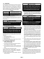
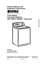
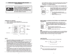
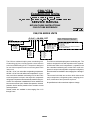
5HYLVHG C0A/C2A SERIES UNITS
C 0 A * - 18- 230 CGT
Unit Type
C - Condensing Unit
H - Heat Pump Outdoor Unit
Efficiency
0 - 10 SEER
1 - 11 SEER
2 - 12 SEER
Voltage
230 - 208/230v, 1ph, 60hz
233 - 208/230v, 3ph, 60hz
460 - 460v, 3ph, 60hz
575 - 575v, 3 ph, 60hp
Generation
Color
L - Beige
G - Gray
B - Brown
R - Green
S - Silver
NOTE - Shaded area denotes part of
model no. referenced in publication.
Options
G - Government option
C - Canadian
T - Technicoat
(If unit has no options, this section is excluded
from the model number.)
Capacity (Nominal)
18 - 1.5 Ton
24 - 2 Ton
30 - 2.5 Ton
36 - 3 Ton
42 - 3.5 Ton
48 - 4 Ton
60 - 5 Ton
The C0A is a residential split-system condensing unit.
Condensing coil size, circuiting and air volume result in
a minimum SEER rating of 10.0. The series is designed
for use with an expansion valve or orifice system in the
indoor unit.
All C0A 1-1/2 to 3 ton units utilize reciprocating compressors.
All C0A 3-1/2 to 5 ton units utilize scroll compressors. It operates much like a standard condensing unit, but the C0A’s
scroll compressor is unique in the way that it compresses
refrigerant.Compressors are hermetically sealed for long service life. The compressor is installed in the unit on resilient rubber mounts to assure quiet, vibration-free operation. A built-in
protection device assures protection from excessive current
and temperatures.
Several models are available in sizes ranging from 1-1/2
through 5 tons.
The C2A is a residential split-system condensing unit . The
series is designed for use with expansion valve systems.
All C2A units utilize scroll compressors. It operates much
like a standard condensing unit, but the C2A’s scroll compressor is unique in the way that it compresses refrigerant.
Several models are available in sizes ranging from 2 through 5
tons.
This manual is divided into sections which discuss the
major components, refrigerant system, charging procedure, maintenance and operation sequence.
All specifications in this manual are subject to change.
Page 1
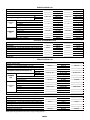
SPECIFICATIONS C0A
Model No.
Nominal Tonnage (kW)
Liquid line - o.d. connection (sweat) - in. (mm)
Suction line - o.d. connection (sweat) - in. (mm)
lbs.
Refrigerant charge furnished (HCFC-22)
(HCFC 22)
kg
Net face area - sq. ft. (m2)
Tube diameter - in. (mm)
Condenser
No. of rows
Coil
Co
Fins per inch (m)
Diameter - in. (mm)
No. of blades
Motor hp (W)
Condenser
Cfm (L/s)
Fan
Rpm
Watts
Shipping weight - lbs. (kg) 1 package
C0A*-18-230
1.5 (5.3)
3/8 (9.5)
5/8 (15.9)
4 lbs. 0 oz.
1.81
10.46 (0.97)
5/16 (7.9)
1
18 (709)
18 (457)
3
1/6 (124)
2170 (1025)
1100
254
136 (62)
o
C0A*-24-230
2 (7.0)
3/8 (9.5)
5/8 (15.9)
4 lbs. 9 oz.
2.07
10.46 (0.97)
5/16 (7.9)
1
18 (709)
18 (457)
3
1/6 (124)
2170 (1025)
1100
254
136 (62)
C0A*-30-230
2.5 (8.8)
3/8 (9.5)
3/4 (19.1)
5 lbs. 0 oz.
2.27
10.46 (0.97)
5/16 (7.9)
1
18 (709)
18 (457)
3
1/6 (124)
2170 (1025)
1100
254
136 (62)
C0A*-36-230
3 (10.6)
3/8 (9.5)
3/4 (19.1)
4 lbs. 14 oz.
2.21
11.41 (1.06)
5/16 (7.9)
1
22 (866)
18 (457)
3
1/4 (187)
2510 (1185)
1103
266
140 (64)
68887
45F08
17L71
24H77
69J06
47J27
94J45
69J1701
68887
45F08
17L73
24H77
69J06
47J27
94J45
53J3901
OPTIONAL ACCESSORIES C0A
Compressor Crankcase Heater
Compressor Monitor (Optional for Canada Only)
Hail Guards
Low Ambient Kit - for use with expansion valve systems only
Mounting Base
Timed-Off Control
Unit Stand Off Kit
Compressor Sound Cover
68887
45F08
17L71
24H77
69J06
47J27
94J45
69J1701
68887
45F08
17L71
24H77
69J06
47J27
94J45
69J1701
o
*Variable field
Refrigerant charge sufficient for 20 ft. (6.0 m) length of refrigerant lines.
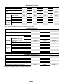
SPECIFICATIONS C0A
Model No.
Nominal Tonnage (kW)
Liquid line - o.d. connection (sweat) - in. (mm)
Suction line - o.d. connection (sweat) - in. (mm)
lbs.
Refrigerant charge furnished (HCFC-22)
(HCFC 22)
kg
Outer coil
2
Net face area - sq
sq. ft.
ft (m )
Inner coil
Condenser
Tube diameter - in. (mm)
Coil
No. of rows
Fins per inch (m)
Diameter - in. (mm)
No. of blades
Motor hp (W)
Condenser
Cfm (L/s)
Fan
Rpm
Watts
Shipping weight - lbs. (kg) 1 package
C0A*-42-230
3.5 (12.3)
3/8 (9.5)
7/8 (22.2)
5 lbs. 12 oz.
2.61
13.31 (1.24)
---5/16 (7.9)
1
22 (866)
18 (457)
4
1/3 (249)
2800 (1320)
1116
299
138 (63)
o
C0A*-48-230
4 (14.1)
3/8 (9.5)
7/8 (22.2)
7 lbs. 4 oz.
3.29
15.11 (1.40)
5.4 (0.50)
5/16 (7.9)
1
22 (866)
18 (457)
4
1/3 (249)
2950 (1390)
1100
310
196 (890
C0A*-60-230
5 (17.6)
3/8 (9.5)
1-1/8 (28.6)
8 lbs. 6 oz.
3.80
20.83 (1.94)
---5/16 (7.9)
1
22 (866)
22 (559)
4
1/3 (249)
3900 (1840)
1100
367
199 (90)
90P12
45F08
17L73
24H77
69J06
47J27
94J45
69J0301
90P12
45F08
17L73
24H77
69J06
47J27
94J45
69J0301
OPTIONAL ACCESSORIES C0A
Compressor Crankcase Heater
Compressor Monitor (Optional for Canada Only)
Hail Guards
Low Ambient Kit - for use with expansion valve systems only
Mounting Base
Timed-Off Control
Unit Stand Off Kit
Compressor Sound Cover
90P12
45F08
17L73
24H77
69J06
47J27
94J45
69J0301
o
*Variable field
Refrigerant charge sufficient for 20 ft. (6.0 m) length of refrigerant lines.
Page 2
ELECTRICAL DATA C0A
Model No.
C0A*-18-230 C0A*-24-230 C0A*-30-230 C0A*-36-230 C0A*-42-230 C0A*-48-230 C0A*-60-230
Line voltage data - 60 hz - 1 phase
208/230v
208/230v
208/230v
208/230v
208/230v
208/230v
208/230v
Rec. max. fuse/circuit breaker size
(amps)
20
25
30
35
40
50
60
11.7
14.4
17.2
20.4
24.3
29.2
33.2
Rated load amps
7.95
10.1
12.4
14.9
17.9
21.8
25
Locked rotor amps
48.3
60
69.4
96
103
103
170
Power factor
0.97
0.96
0.92
0.89
0.84
0.80
0.90
Full load amps
1.1
1.1
1.1
1.7
1.9
1.9
1.9
Locked rotor amps
1.9
1.9
1.9
3.1
4.1
4.1
4.1
oMinimum circuit ampacity
Compressor
Condenser
Coil
Fan Motor
o
q
*Variable Field.
Refer to National or Canadian Electrical Code manual to determine wire, fuse and disconnect size requirements.
NOTE — Extremes of operating range are plus 10% and minus 5% of line voltage.
Most popular evaporator coil match.
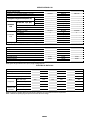
SPECIFICATIONS C2A
Model No.
Nominal Tonnage (kW)
Liquid line - o.d. connection (sweat) - in. (mm)
Suction line - o.d. connection (sweat) - in. (mm)
lbs.
Refrigerant charge furnished (HCFC-22)
(HCFC 22)
kg
Outer coil
Net face area - sq
sq. ft.
ft (m2)
Inner coil
Condenser
Tube diameter - in. (mm)
Coil
No. of rows
Fins per inch (m)
Diameter - in. (mm)
No. of blades
Motor hp (W)
Condenser
Fan
Cfm (L/s)
Rpm
Watts
Shipping weight - lbs. (kg) 1 package
C2A*-24-230
2 (7.0)
3/8 (9.5)
3/4 (19.1)
5 lbs. 8 oz.
2.49 kg
15.21 (1.41)
5.44 (0.51)
5/16 (7.9)
1.37
22 (866)
18 (457)
3
1/6 (124)
2500 (1180)
1100
200
155 (70)
o
C2A*-30-230
2.5 (8.8)
3/8 (9.5)
3/4 (19.1)
7 lbs. 3 oz.
3.26 kg
15.21 (1.41)
14.50 (1.35)
5/16 (7.9)
2
22 (866)
18 (457)
4
1/6 (124)
2450 (1155)
1100
200
175 (79)
C2A*-36-230
3 (10.6)
3/8 (9.5)
7/8 (22.2)
7 lbs. 4 oz.
3.29 kg
15.21 (1.41)
14.50 (1.35)
5/16 (7.9)
2
22 (866)
18 (457)
4
1/6 (124)
2450 (1155)
1100
200
180 (82)
90P12
69J0301
17L73
24H77
69J06
47J27
94J45
45F08
90P12
69J0301
17L73
24H77
69J06
47J27
94J45
45F08
OPTIONAL ACCESSORIES C2A
Compressor Crankcase Heater
Compressor Sound Cover
Hail Guards
Low Ambient Kit - for use with expansion valve systems only
Mounting Base
Timed-Off Control
Unit Stand Off Kit
Compressor Monitor (Optional for Canada Only)
o
*Variable field
Refrigerant charge sufficient for 20 ft. (6.0 m) length of refrigerant lines.
Page 3
90P12
69J0301
17L73
24H77
69J06
47J27
94J45
45F08
SPECIFICATIONS C2A
Model No.
Nominal Tonnage (kW)
Liquid line - o.d. connection (sweat) - in. (mm)
Suction line - o.d. connection (sweat) - in. (mm)
lbs.
Refrigerant charge furnished (HCFC-22)
(HCFC 22)
kg
Outer coil
Net face area - sq
sq. ft.
ft (m2)
Inner coil
Condenser
Tube diameter - in. (mm) & no. of rows
Coil
No. of rows
Fins per inch (m)
Diameter - in. (mm)
No. of blades
Motor hp (W)
Condenser
Fan
Cfm (L/s)
Rpm
Watts
Shipping weight - lbs. (kg) 1 package
C2A*-42-230
3.5 (12.3)
3/8 (9.5)
7/8 (22.2)
7 lbs. 11 oz.
3.49 kg
15.21 (1.41)
14.50 (1.35)
5/16 (7.9)
2
22 (866)
18 (457)
4
1/3 (249)
2930 (1385)
1100
310
186 (84)
o
C2A*-48-230
4 (14.1)
3/8 (9.5)
7/8 (22.2)
10 lbs. 14 oz.
4.93 kg
21.11 (1.96)
20.31 (1.89)
5/16 (7.9)
2
22 (866)
22 (559)
4
1/3 (249)
3890 (1835)
1085
375
250 (113)
C2A*-60-230
5 (17.6)
3/8 (9.5)
1-1/8 (28.6)
11 lbs. 0 oz.
4.99 kg
21.11 (1.96)
20.31 (1.89
5/16 (7.9)
2
22 (866)
22 (559)
4
1/3 (249)
3890 (1835)
1085
375
254 (115)
90P12
00000
11L74
24H77
69J07
47J27
94J45
45F08
90P12
00000
11L74
24H77
69J07
47J27
94J45
45F08
OPTIONAL ACCESSORIES C2A
Compressor Crankcase Heater
Compressor Sound Cover
Hail Guards
Low Ambient Kit - for use with expansion valve systems only
Mounting Base
Timed-Off Control
Unit Stand Off Kit
Compressor Monitor (Optional for Canada Only)
90P12
00000
11L73
24H77
69J06
47J27
94J45
45F08
o
*Variable field
Refrigerant charge sufficient for 20 ft. (6.0 m) length of refrigerant lines.
ELECTRICAL DATA C2A
Model No.
C2A*-24-230
C2A*-30-230
C2A*-36-230
C2A*-42-230
C2A*-48-230
C2A*-60-230
208/230v
208/230v
208/230v
208/230v
208/230v
208/230v
20
30
35
40
50
60
14.0
18.0
20.4
24.4
31.5
38.0
Rated load amps
10.3
13.5
15.4
18.0
23.7
28.9
Locked rotor amps
56.0
72.5
88.0
104.0
129.0
169.0
Power factor
.96
.96
.96
.95
.96
.96
1.1
1.1
1.1
1.9
1.9
1.9
1.9
1.9
1.9
4.1
4.1
4.1
Line voltage data - 60 hz - 1 phase
Rec. max. fuse/circuit breaker size (amps)
oMinimum circuit ampacity
Compressor
Condenser Coil Full load amps
Fan Motor
Locked rotor amps
o
*Variable Field.
Refer to National or Canadian Electrical Code manual to determine wire, fuse and disconnect size requirements.
NOTE — Extremes of operating range are plus 10% and minus 5% of line voltage.
Page 4
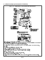
I - UNIT INFORMATION
C0A/C2A UNIT CONTROL BOX
C0A condensing units are available in 1-1/2, 2, 2 -1/2, 3, 3
-1/2, 4 and 5 ton capacities. C2A condensing units are available in 2, 2-1/2, 3, 3-1/2, 4 and 5 ton capacities.
All major components (indoor blower and coil) must be
matched according to recommendations for the compressor
to be covered under warranty. Refer to the Engineering Handbook for approved system matchups. A misapplied system will
cause erratic operation and can result in early compressor failure.
DUAL CAPACITOR
(C12)
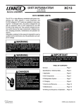
II - UNIT COMPONENTS
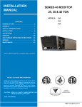
C0A unit components are illustrated in figure 1. C2A components are illustrated in figure 2.
COMPRESSOR
CONTACTOR
(K1)
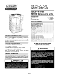
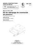
C0A UNIT COMPONENTS
OUTDOOR
FAN/MOTOR
CONTROL
BOX
GROUNDING
LUG
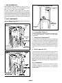
FIGURE 3
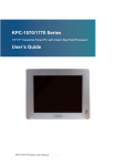
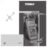
A - Control Box (Figure 3)
Electrical openings are provided under the control box cover. Field thermostat wiring is made to color-coded pigtail
connections.
1 - Compressor Contactor K1
DISCHARGE
LINE
SUCTION LINE
SERVICE VALVE
COMPRESSOR
LIQUID LINE
SERVICE VALVE
The compressor is energized by a contactor located in the
control box. See figure 3. Single-pole contactors are used
in all C0A/C2A series units. K1 is energized by the indoor
thermostat terminal Y1 (24V) when thermostat demand is
present. C0A/C2A units are not equipped with a 24 volt
transformer. All 24 volt controls are powered by the indoor
unit.
SUCTION LINE
2 - Dual Capacitor C12
FIGURE 1
OUTDOOR
FAN/MOTOR
C2A UNIT COMPONENTS
The compressor and fan in C0A/C2A series units use
permanent split capacitor motors. The capacitor is located inside the unit control box (see figure 3). A single
“dual” capacitor (C12) is used for both the fan motor and
the compressor (see unit wiring diagram). The fan side
and the compressor side of the capacitor have different
MFD ratings. Capacitor ratings may change with compressor.
CONTROL
BOX
B - Compressor
SUCTION
LINE
SUCTION LINE
SERVICE VALVE
All C0A 1-1/2 to 3 ton units utilize a conventional reciprocating compressor. C0A 3-1/2 to 5 ton units use
scrolls. See Electrical Data section for compressor
specifications.
COMPRESSOR
DISCHARGE LINE
LIQUID LINE
SERVICE VALVE
FIGURE 2
Page 5
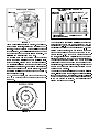
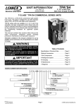
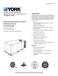
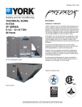
&5266 6(&7,21 2) 6&52//6
6&52// &2035(6625
',6&+$5*(
',6&+$5*(
35(6685(
',6&+$5*(
67$7,21$5< 6&52//
68&7,21
68&7,21
25%,7,1* 6&52//
7,36 6($/(' %<
',6&+$5*( 35(6685(
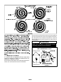
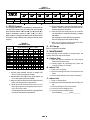
),*85( ),*85( The counterclockwise orbiting scroll draws gas into the
All C2A units utilize a scroll compressor. The scroll com-
outer crescent shaped gas pocket created by the two
pressor design is simple, efficient and requires few mov-
scrolls (figure 7 -- 1). The centrifugal action of the orbiting
ing parts. A cutaway diagram of the scroll compressor is
shown in figure 4. The scrolls are located in the top of the
compressor can and the motor is located just below.
The
oil level is immediately below the motor.
The scroll is a simple compression concept centered
around the unique spiral shape of the scroll and its in-
scroll seals off the flanks of the scrolls (figure 7 -- 2). As the
orbiting motion continues, the gas is forced toward the
center of the scroll and the gas pocket becomes compressed (figure 7 -- 3). When the compressed gas reaches
the center, it is discharged vertically into a chamber and
discharge port in the top of the compressor (figure 6).
The discharge pressure forcing down on the top scroll
herent properties. Figure 5 shows the basic scroll form.
helps seal off the upper and lower edges (tips) of the
Two identical scrolls are mated together forming concen-
scrolls (figure 6). During a single orbit, several pockets of
tric spiral shapes (figure 6). One scroll remains stationary,
gas are compressed simultaneously providing smooth
while the other is allowed to orbit (figure 7). Note that
continuous compression.
the orbiting scroll does not rotate or turn but merely or-
The scroll compressor is tolerant to the effects of liquid
bits the stationary scroll.
return. If liquid enters the scrolls, the orbiting scroll is al-
NOTE -- During operation, the head of a scroll compres-
lowed to separate from the stationary scroll. The liquid is
sor may be hot since it is in constant contact with dis-
worked toward the center of the scroll and is discharged.
If the compressor is replaced, conventional Lennox
charge gas.
cleanup practices must be used.
6&52// )250
),*85( Page 6
SUCTION
SUCTION
POCKET
HOW A SCROLL WORKS
MOVEMENT OF ORBIT
SUCTION
INTERMEDIATE
PRESSURE
GAS
CRESCENT
SHAPED GAS
POCKET
ORBITING
SCROLL
1
STATIONARY SCROLL
2
SUCTION
3
MOVEMENT OF ORBIT
HIGH
PRESSURE GAS
FLANKS
SEALED BY
CENTRIFUGAL FORCE
SUCTION
4
DISCHARGE
POCKET
FIGURE 7
Due to its efficiency, the scroll compressor is capable of
drawing a much deeper vacuum than reciprocating
compressors. Deep vacuum operation can cause internal fusite arcing resulting in damaged internal
parts and will result in compressor failure. Never use
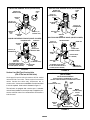
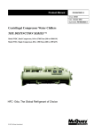
Access to the condenser fan motor on all units is gained
by removing the seven screws securing the fan assembly. See figure 8. The condenser fan motor is removed
from the fan guard by removing the four nuts found on
the top panel.
'$1*(5
a scroll compressor for evacuating or pumping-down the system. This type of damage can be detected and will result in denial of warranty claims.
The scroll compressor is quieter than a reciprocating
compressor, however, the two compressors have much
different sound characteristics. The sounds made by a
Make sure all power is disconnected before
beginning electrical service procedures.
CONDENSER FAN MOTOR
AND COMPRESSOR ACCESS
scroll compressor do not affect system reliability, perfor-
Remove (7) screws
mance, or indicate damage.
See Electrical section for scroll compressor specifica-
FAN GUARD
FAN
tions.
C - Condenser Fan Motor
All C0A/C2A units use single-phase PSC fan motors which
require a run capacitor. In all units, the condenser fan is controlled by the compressor contactor.
ELECTRICAL DATA tables in this manual show specifications for condenser fans used in C0A/C2As.
MOTOR
WIRING
RACEWAY
Remove (4) nuts
REMOVE (7) SCREWS
SECURING FAN GUARD.
REMOVE FAN GUARD/FAN
ASSEMBLY.
FIGURE 8
Page 7
III - REFRIGERANT SYSTEM
A - Plumbing
B - Service Valves
Field refrigerant piping consists of liquid and suction lines
from the condensing unit (sweat connections) to the indoor
evaporator coil (flare or sweat connections). Use L10
(flare) or L15 (sweat, non-flare) series line sets as shown
in tables 1 or 2 or use field-fabricated refrigerant lines.
Separate discharge and suction service ports are provided outside the unit for connection of gauge manifold
during charging procedure.
TABLE 1
Condensing
Line Set
Unit
Model No.
Model No.
C0A--18
C0A
18
C0A--24
C0A -30
C0A30
C0A -36
C0A36
C0A -42
C0A42
C0A--48
C0A60
Length of
Lines
(L10 or L15)
ft.
m
L10/15-21-20
20
6
L10/15-21-25
25
8
L10/15-21-35
35
11
L10/15-21-50
50
15
L15-31-20
20
6
L15-31-30
30
9
L15-31-40
40
12
L15-31-50
50
15
L10/15-41-20
20
6
L10/15-41-30
30
9
L10/15-41-40
40
12
L10/15-41-50
50
15
L10/15-65-30
30
9
L10/15-65-40
40
12
L10/15-65-50
50
15
*Field fabricate
Liquid Line
Suction Line
Outside Dia. Outside Dia.
in.
mm
in.
mm
5/16
7 9
7.9
5/8
15 9
15.9
5/16
7 9
7.9
3/4
19
3/8
9 5
9.5
3/4
19
The liquid and suction line service valves (figures 9, 10 and
11) and gauge ports are accessible from outside the unit.
The valve is equipped with a service port. The service ports
are used for leak testing, evacuating, charging and checking
charge. A schrader valve is factory installed. A service port cap
is supplied to protect the schrader valve from contamination
and serve as the primary leak seal.
NOTE-Always keep valve stem caps clean.
To Access Schrader Port:
1 - Remove service port cap with an adjustable wrench.
2 - Connect gauge to the service port.
3 - When testing is completed, replace service port cap.
Tighten finger tight, then an additional 1/6 turn.
To Open Liquid or Suction Line Service Valve:
1 - Remove stem cap with an adjustable wrench.
2 - Using service wrench and hex head extension (5/16” for
suction line and 3/16” for liquid line) back the stem out
counterclockwise until the valve stem just touches the
retaining ring.
3 - Replace stem cap tighten firmly. Tighten finger tight, then
tighten an additional 1/6 turn.
'$1*(5
3/8
9.5
9
5
7/8
/8
22.2
3/8
9.5
1-1/8
28.5
Do not attempt to backseat this valve. Attempts to
backseat this valve will cause snap ring to explode
from valve body under pressure of refrigerant.
Personal injury and unit damage will result.
*Field fabricate.
TABLE 2
Condensing
Line Set
Unit
Model No.
Model No.
(L10 or L15)
L10-41-20
L15-41-20
L10-41-30
C2A--24
C2A--30
L15-41-30
L10-41-40
L15-41-40
L10-41-50
L15-41-50
L10-65-30
L15-65-30
C2A--36
C2A--42
C2A
48
C2A--48
L10-65-40
L15-65-40
L10-65-50
L15-65-50
C2A60
Length of
Liquid Line
Suction Line
Lines
Outside Dia.
Outside Dia.
ft.
m
20
6
30
9
40
12
50
15
30
9
40
12
50
15
*Not available
in.
mm
in.
mm
3/8
9 5
9.5
3/4
19
3/8
9.5
7/8
22.2
3/8
9.5
1-1/8
28.5
To Close Liquid or Suction Line Service Valve:
1 - Remove stem cap with an adjustable wrench.
2 - Using service wrench and hex head extension (5/16” for
suction line and 3/16” for liquid line) , turn stem clockwise
to seat the valve. Tighten firmly.
3 - Replace stem cap. Tighten finger tight, then tighten an
additional 1/6 turn.
*Field fabricate.
Page 8
LIQUID LINE SERVICE VALVE (VALVE OPEN)
SUCTION LINE SERVICE VALVE (VALVE OPEN)
STEM
CAP
INSERT HEX
WRENCH HERE
STEM
CAP
INSERT HEX
WRENCH HERE
INLET (TO
INDOOR COIL)
SERVICE
PORT
OUTLET (TO
COMPRESSOR)
SCHRADER
VALVE
OUTLET (TO
COMPRESSOR)
SERVICE
PORT
CAP
SERVICE PORT
CAP
INLET (TO
INDOOR COIL)
SCHRADER
VALVE
SERVICE
PORT
SUCTION LINE SERVICE VALVE (VALVE CLOSED)
LIQUID LINE SERVICE VALVE (VALVE CLOSED)
RETAINING RING
STEM CAP
INLET (TO
INDOOR COIL)
SERVICE
PORT
RETAINING RING
INSERT HEX
WRENCH HERE
INSERT HEX
WRENCH HERE
OUTLET (TO
COMPRESSOR)
STEM CAP
SERVICE
PORT
(VALVE FRONT
SEATED)
SERVICE
PORT CAP
SCHRADER VALVE OPEN
TO LINE SET WHEN VALVE IS
CLOSED (FRONT SEATED)
INLET
(TO INDOOR COIL)
SERVICE PORT
CAP
(VALVE FRONT
SEATED)
SCHRADER VALVE OPEN
TO LINE SET WHEN VALVE IS
CLOSED (FRONT SEATED)
FIGURE 9
OUTLET (TO
COMPRESSOR)
FIGURE 10
Suction Line (Ball Type) Service Valve
(C0A 5 Ton and all C2A Units)
SUCTION LINE (BALL TYPE) SERVICE VALVE
(VALVE OPEN)
A ball-type full service valve is used on all C2A model
units and C0A 5 ton units. These suction line service
valves function the same way, differences are in
construction. Valves are not rebuildable. If a valve has failed
it must be replaced. A ball valve is illustrated in figure 11.
USE ADJUSTABLE WRENCH
ROTATE STEM CLOCKWISE 90E TO CLOSE
ROTATE STEM COUNTER-CLOCKWISE 90E TO OPEN
STEM
CAP
INLET
(FROM INDOOR COIL)
The ball valve is equipped with a service port. A schrader
valve is factory installed. A service port cap is supplied to protect the schrader valve from contamination and assure a
leak free seal.
STEM
BALL
(SHOWN OPEN)
OUTLET
(TO
COMPRESSOR)
SERVICE
PORT
CAP
SERVICE
PORT
SCHRADER CORE
FIGURE 11
Page 9
CAUTION
IV - CHARGING
The unit is factory-charged with the amount of R-22 refrigerant indicated on the unit rating plate. This charge is
based on a matching indoor coil and outdoor coil with a 20
foot (6.1 m) line set. For varying lengths of line set, refer to
table 3 for refrigerant charge adjustment. A blank space is provided on the unit rating plate to list actual field charge.
TABLE 3
LIQUID LINE
SET DIAMETER
1/4 in. (6 mm)
5/16 in. (8mm)
3/8 in. (10 mm)
When using dry nitrogen, a pressure reducing regulator must be used to prevent excessive pressure in gauge manifold, connecting hoses, and
within the system. Regulator setting must not exceed 150 psig (1034 kpa). Failure to use a regulator
can cause equipment failure resulting in injury.
C - Evacuating the System
Ounce per 5 foot (ml. per mm) adjust
from 20 foot (6.1 m) line set*
1- Attach gauge manifold. Connect vacuum pump (with vacuum gauge) to center port of gauge manifold. With both
manifold service valves open, start pump and evacuate
indoor coil and refrigerant lines.
1 ounce per 5 feet (30 ml per 1524 mm)
2 ounce per 5 feet (60 ml per 1524 mm)
3 ounce per 5 feet (90 ml per 1524 mm)
IMPORTANT
*If line set is greater than 20 ft. (6.1 m) add this amount. If line set
is less than 20 feet (6.1 m) subtract this amount
Units are designed for line sets up to 50 ft (15.2 m). Consult Lennox Refrigerant Piping Manual for line sets over
50 ft (15.2 m).
A temperature vacuum gauge, mercury vacuum
(U-tube), or thermocouple gauge should be used.
The usual Bourdon tube gauges are not accurate
enough in the vacuum range.
IMPORTANT
IMPORTANT
If line length is greater than 20 feet (6.1 m) add this
amount. If line length is less than 20 feet (6.1 m),
subtract this amount.
The compressor should never be used to evacuate a refrigeration or air conditioning system.
A - Pumping Down System
CAUTION
Deep vacuum operation (operating compressor at 0
psig or lower) can cause internal fusite arcing
resulting in a damaged or failed compressor. This
type of damage will result in denial of warranty claim.
The system may be pumped down when leak checking the
line set and indoor coil or making repairs to the line set or
indoor coil.
1- Attach gauge manifold.
2- Front seat (close) liquid line valve.
3- Start outdoor unit.
4- Monitor suction gauge. Stop unit when 0 psig is reached.
5- Front seat (close) suction line valve.
B - Leak Testing (To Be Done
Before Evacuating)
1- Attach gauge manifold and connect a drum of dry nitrogen to center port of gauge manifold.
2- Open high pressure valve on gauge manifold and
pressurize line set and indoor coil to 150 psig (1034
kPa).
3- Check lines and connections for leaks.
NOTE-If electronic leak or Halide detector is used, add a
small amount of R-22 (3 to 5 psig [20kPa to 34kPa]) then
pressurize with nitrogen to 150 psig.
4- Release nitrogen pressure from the system, correct any
leaks and recheck.
2- Evacuate the system to 29 inches (737mm) vacuum.
During the early stages of evacuation, it is desirable to
stop the vacuum pump at least once to determine if there
is a rapid loss of vacuum. A rapid loss of vacuum would
indicate a leak in the system and a repeat of the leak
testing section would be necessary.
3- After system has been evacuated to 29 inches
(737mm), close gauge manifold valves to center port,
stop vacuum pump and disconnect from gauge manifold. Attach an upright nitrogen drum to center port of
gauge manifold and open drum valve slightly to purge
line at manifold. Break vacuum in system with nitrogen pressure by opening manifold high pressure
valve. Close manifold high pressure valve to center
port.
4- Close nitrogen drum valve and disconnect from
gauge manifold center port. Release nitrogen pressure from system.
5- Connect vacuum pump to gauge manifold center
port. Evacuate system through manifold service
valves until vacuum in system does not rise above
.5mm of mercury absolute pressure or 500 microns
within a 20-minute period after stopping vacuum pump.
6- After evacuation is complete, close manifold center port,
and connect refrigerant drum. Pressurize system
slightly with refrigerant to break vacuum.
D - Charging
If the system is completely void of refrigerant, the recommended and most accurate method of charging is to weigh
the refrigerant into the unit according to the total amount
shown on the unit nameplate. Also refer to the tables in the
SPECIFICATIONS section of this manual.
Page 10
If weighing facilities are not available or if unit is just low on
charge, the following procedure applies.
Add refrigerant slowly as the unit approaches the
correct temperature. This will allow refrigerant
to stabilize allowing the correct temperature to
be read.
TABLE 4
COA
1 - Expansion Valve Systems
The following procedures are intended as a general guide for
use with expansion valve systems only. For best results, indoor temperature should be between 70qF and 80qF (21.1qC
and 26.7qC). Outdoor temperature should be 60qF (15.6qC) or
above. Slight variations in charging temperature and pressure
should be expected. Large variations may indicate need for
further servicing.
IMPORTANT
C0A-18
C0A-24
C0A-30
IMPORTANT
1 - Connect gauge manifold. Connect an upright R-22
drum to center port of gauge manifold.
2 - Record outdoor air (ambient) temperature.
3 - Operate indoor and outdoor units in cooling mode.
Allow outdoor unit to run until system pressures stabilize.
4 - Make sure thermometer well is filled with mineral oil
before checking liquid line temperature.
Use tables 6 and 7 as a general guide for performing maintenance checks. Tables 6 and 7 are is not
a procedure for charging the system. Minor variations in these pressures may be expected due to
differences in installations. Significant deviations
could mean that the system is not properly charged
or that a problem exists with some component in
the system. Used prudently, tables 6 and 7 could
serve as a useful service guide.
5 - Place thermometer in well and read liquid line temperature. Liquid line temperature should be warmer
than the outdoor air temperature. Tables 4 and 5
shows how many degrees warmer the liquid line
temperature should be.
Add refrigerant to lower the liquid line temperature.
Recover refrigerant to raise the liquid line temperature.
TABLE 6
C0A Model Units
OUTDOOR COIL
ENTERING AIR
TEMPERATURE
4 (2.2)
5 (2.8)
10 (5.6)
6 - When unit is properly charged, liquid line pressures should approximate those in tables 6, and 7 .
APPROACH METHOD (TXV SYSTEMS)
(Ambient Temperature of 60EF [16EC] or Above)
C0A-24
LIQ.
SUC.
+ 10
+ 10
PSIG PSIG
Liquid Line EF (EC)
- Outdoor Temperature EF (EC)
C0A-36
12 (6.7)
C0A-42
12 (6.7)
C0A-48
13 (7.2)
C0A-60
13 (7.2)
Note-For best results, the same electronic thermometer should be
used to check both outdoor and liquid temperatures.
The following procedure requires accurate readings of ambient (outdoor) temperature, liquid temperature and liquid pressure for proper charging.
Use a thermometer with accuracy of +2 qF (+ 1.1qC)
and a pressure gauge with accuracy of +5 PSIG (
+34.5 kPa).
C0A-18
LIQ. SUC.
+ 10
+ 10
PSIG PSIG
Approach Temperature
Model
Number
TABLE 5
C2A
Model
APPROACH TEMPERATURE
LIQUID LINE
E F -- OUTDOOR AMBIENT E F
C2A--24
10qF (5.5qC)
C2A--30
8qF (4.4qC)
C2A--36
7qF (3.8qC)
C2A--42
8qF (4.4qC)
NORMAL OPERATING PRESSURES*
C0A-30
C0A-36
C0A-42
LIQ. SUC. LIQ.
SUC.
LIQ. SUC.
+ 10
+ 10
+ 10
+ 10
+ 10
+ 10
PSIG PSIG PSIG PSIG PSIG PSIG
C0A-48
SUC.
LIQ.
+ 10
+ 10
PSIG
PSIG
C0A-60
LIQ.
SUC.
+ 10
+ 10
PSIG
PSIG
65qF (18.3qC) (RFCIV)
65
181
64
174
62
176
63
168
65
160
65
155
----------70
208
69
205
66
203
68
197
70
188
70
181
-----75qF (23.9qC) (RFCIV)
-----85qF (29.4qC) (RFCIV)
75
239
73
236
70
233
73
227
74
216
75
208
----------79
271
77
271
74
266
77
258
78
247
80
238
----------95qF (35.0qC) (RFCIV)
-----82
306
80
305
77
299
80
292
82
280
84
-----105qF (40.6qC) (RFCIV) 270
65qF (18.3qC) (TXV)
159
174
73
70
164
71
173
71
179
68
180
71
187
73
208
73
183
203
75
72
189
73
199
73
205
70
212
75
75qF (23.92qC) (TXV)
85qF (31.2qC) (TXV)
238
75
209
235
77
74
217
75
228
75
235
72
241
77
95qF (31.2qC) (TXV)
271
77
238
269
80
76
247
78
258
77
266
74
271
79
269
306
82
78
279
80
292
79
299
77
305
79
305
80
105qF (31.2qC) (TXV)
*These are typical pressures only. Indoor evaporator match up, indoor air quality and evaporator load will cause the pressures to vary.
Page 11
TABLE 7
C2A Model Units
NORMAL OPERATING PRESSURES*
C2A--24
OUTDOOR COIL
C2A--30
C2A--36
C2A--42
LIQ.
SUC.
LIQ.
SUC.
LIQ.
SUC.
LIQ.
+10
+ 10
+10
+ 10
+10
+ 10
+10
+ 10
PSIG
PSIG
PSIG
PSIG
PSIG
PSIG
PSIG
PSIG
82qF (47.2qC)
187
77
180
72
190
73
187
79
95qF (52.8qC)
226
79
219
74
229
75
229
80
ENTERING AIR
TEMPERATURE
SUC.
*These are typical pressures only. Indoor evaporator match up, indoor air quality and evaporator load will cause the pressures to vary.
5 - Place thermometer in well and read liquid line temperature. Table 8 shows how much warmer the condensing temperature should be.
6 - Subtract liquid line temperature from condensing temperature to determine subcooling. Compare
with table 8.
Add refrigerant to lower liquid line temperature.
Recover refrigerant to raise liquid line temp.
7 - When unit is properly charged liquid line pressures should approximate table 6.
2 - RFCIV Systems
The following procedures are intended as a general guide for
use with RFCIV systems only. For best results, indoor temperature should be between 70qF and 80qF (21.1qC and 26.7qC).
Outdoor temperature should be 60qF (15.6qC) or above.
Slight variations in charging temperature and pressure should
be expected. Large variations may indicate a need for further
servicing.
TABLE 8
C0A Model Units
Outdoor
Temperature
EF(EC)
E - Oil Charge
Liquid Subcooling (+ 1EF or 0.5 EC)
C0A-30
C0A-36
60 (16)
17 (9.5)
18 (10)
18 (10)
14 (8)
16 (8.9)
15 (8.3)
65 (18)
16 (8.9)
16 (8.9)
17 (9.5)
13 (7.8)
15 (8.3)
14 (8)
70 (21)
15 (8.3)
14 (8)
16 (8.9)
12 (6.7)
14 (8)
13 (7.8)
75 (24)
14 (8)
12 (6.7)
15 (8.3)
10 (5.6)
13 (7.8)
11 (6.1)
80 (27)
13 (7.8)
11 (6.1)
14 (8)
9 (5)
12 (6.7)
10 (5.6)
85 (29)
12 (6.7)
10 (5.6)
13 (7.8)
8 (4.4)
11 (6.1)
8 (4.4)
90 (32)
11 (6.1)
9 (5)
12 (6.7)
7 (3.9)
10 (5.6)
7 (3.9)
95 (35)
9 (5)
8 (4.4)
11 (6.1)
6 (3.3)
9 (5)
7 (3.9)
100 (38)
8 (4.4)
7 (3.9)
10 (5.6)
5 (2.8)
8 (4.4)
6 (3.3)
105 (41)
7 (3.9)
6 (3.3)
9 (5)
4 (2.2)
6 (3.3)
4 (2.2)
110 (43)
6 (3.3)
6 (3.3)
7 (3.9)
3 (1.7)
5 (2.8)
3 (1.7)
115 (46)
5 (2.8)
5 (2.8)
5 (2.8)
2 (1.1)
3 (1.7)
2 (1.1)
C0A-18
C0A-24
C0A-42
Refer to compressor nameplate.
C0A--48
V - MAINTENANCE
At the beginning of each heating or cooling season, the
system should be cleaned as follows:
A - Outdoor Unit
1 - Clean and inspect condenser coil. (Coil may be
flushed with a water hose).
2 - Visually inspect all connecting lines, joints and
coils for evidence of oil leaks.
B - Indoor Coil
1 - Clean coil if necessary.
2 - Check connecting lines and coil for evidence of oil
leaks.
3 - Check condensate line and clean if necessary.
1 - Connect gauge manifold. Connect an upright R-22
drum to center port of gauge manifold.
2 - Operate indoor and outdoor units. Allow outdoor unit
to run until system pressures stabilize.
C - Indoor Unit
3 - Make sure thermometer well is filled with mineral oil
before checking liquid line temperature.
4 - Read liquid line pressure and convert to condensing temperature using temperature/ pressure conversion chart.
Condensing temperature (read from gauges) should
be warmer than liquid line temperature.
Page 12
1 - Clean or change filters.
2 - Bearings are pre-lubricated and need no further oiling.
3 - Check all wiring for loose connections.
4 - Check for correct voltage at unit.
5 - Check amp-draw on blower motor.
Unit nameplate_________Actual_________.
VI -- WIRING DIAGRAMS AND SEQUENCE OF OPERATION
C0A 1-1/2 THROUGH 5 TON OPERATING SEQUENCE
1
2
5
6
3
4
7
A--C0A 1-1/2 -- 5 TON OPERATING SEQUENCE
This is the sequence of operation for C0A 1-1/2 through 5 ton units. The sequence is outlined by numbered steps
which correspond to circled numbers on the adjacent diagram.
NOTE-- The thermostat used may be electromechanical or electronic.
NOTE-- Transformer in indoor unit supplies power (24 VAC) to the thermostat and outdoor unit controls.
COOLING:
1 -- Cooling demand initiates at Y1 in the thermostat.
2 -- 24VAC energizes compressor contactor K1.
3 -- K1-1 N.O. closes, energizing compressor (B1) and outdoor fan motor (B4).
4 -- Compressor (B1) and outdoor fan motor (B4) begin immediate operation.
END OF COOLING DEMAND:
5 -- Cooling demand is satisfied. Terminal Y1 is de-energized.
6 -- Compressor contactor K1 is de-energized.
7 -- K1-1 opens and compressor (B1) and outdoor fan motor (B4) are de-energized and stop immediately.
3DJH C2A 2 THROUGH 5 TON OPERATING SEQUENCE
1
6
5
2
3
4
7
C2A 2 -- 5 TON OPERATING SEQUENCE
This is the sequence of operation for C2A 2 through 5 ton units. The sequence is outlined by numbered steps
which correspond to circled numbers on the adjacent diagram.
NOTE-- The thermostat used may be electromechanical or electronic.
NOTE-- Transformer in indoor unit supplies power (24 VAC) to the thermostat and outdoor unit controls.
COOLING:
1 -- Cooling demand initiates at Y1 in the thermostat.
2 -- 24VAC from indoor unit (Y1) energizes compressor contactor K1.
3 -- K1-1 N.O. closes, energizing compressor (B1) and outdoor fan motor (B4).
4 -- Compressor (B1) and outdoor fan motor (B4) begin immediate operation..
END OF COOLING DEMAND:
5 -- Cooling demand is satisfied. Terminal Y1 is de-energized.
6 -- Compressor contactor K1 is de-energized.
7 -- K1-1 opens and compressor (B1) and outdoor fan motor (B4) are de-energized and stop immediately.
3DJH