1
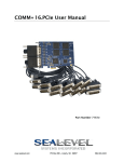
VERSA COMM+4.LPCI
Users Manual
Part Number 7406 and 7406-DB9
Sealevel Systems, Inc.
PO Box 830
Liberty, SC 29657 USA
Telephone: 864.843.4343
Fax: 864.843.3067
www.sealevel.com
Contents
INTRODUCTION ........................................................................................................................ 1
OVERVIEW .............................................................................................................................................. 1
WHAT’S INCLUDED ................................................................................................................................. 1
CARD SETUP ............................................................................................................................ 2
CLOCK MODES ........................................................................................................................................ 2
BAUD RATES AND DIVISORS FOR THE ‘DIV1’ MODE ................................................................................ 3
ADDRESS AND IRQ SELECTION ............................................................................................................... 3
INSTALLATION ......................................................................................................................... 4
OPERATING SYSTEM INSTALLATION ........................................................................................................ 4
Windows 95/98/ME/NT/2000/XP....................................................................................................... 4
Linux ................................................................................................................................................... 4
QNX .................................................................................................................................................... 4
PHYSICAL INSTALLATION ........................................................................................................................ 5
TECHNICAL DESCRIPTION ...................................................................................................... 6
CONNECTOR PIN ASSIGNMENTS .............................................................................................................. 6
DB-25 Female (RS-232 DTE) ............................................................................................................. 6
DB-9 Male (EIA-574 DTE)................................................................................................................. 6
Card Edge DB-44 Female.................................................................................................................... 6
SPECIFICATIONS ...................................................................................................................... 7
ENVIRONMENTAL SPECIFICATIONS .......................................................................................................... 7
MANUFACTURING ................................................................................................................................... 7
POWER CONSUMPTION ............................................................................................................................ 7
PHYSICAL DIMENSIONS ........................................................................................................................... 7
APPENDIX A - TROUBLESHOOTING ........................................................................................ 8
APPENDIX B - HOW TO GET ASSISTANCE .............................................................................. 9
APPENDIX C - ELECTRICAL INTERFACE .............................................................................. 10
RS-232.................................................................................................................................................. 10
APPENDIX D - ASYNCHRONOUS COMMUNICATIONS ............................................................ 11
APPENDIX E - SILK-SCREEN ................................................................................................. 12
APPENDIX F - COMPLIANCE NOTICES .................................................................................. 13
FEDERAL COMMUNICATIONS COMMISSION STATEMENT ....................................................................... 13
EMC DIRECTIVE STATEMENT ............................................................................................................... 13
WARRANTY ............................................................................................................................ 14
© Sealevel Systems, Inc.
SL9066 Revision 7/2006
Sealevel Systems, Incorporated. All rights reserved.
Introduction
Introduction
Overview
The Sealevel Systems VERSA COMM+4.LPCI provides the PC with four RS-232 asynchronous ports. The
VERSA COMM+4.LPCI allows for connection to any device utilizing the RS-232 electrical interface, such as
modems, data-entry terminals, and plotters.
The VERSA COMM+4.LPCI ships with a Low Profile PCI bracket that will only work in a Low Profile PCI slot.
If you need a standard size PCI bracket, please order Item# 7406S.
What is Included
The VERSA COMM+4.LPCI is shipped with the following items. If any of these items is missing or damaged,
contact the supplier.
•
•
•
VERSA COMM+4.LPCI Serial I/O Adapter
Item# 7406 ships with a Low Profile PCI bracket
Item# 7406S ships with a standard size PCI bracket
HDB-44 to Four Connector Fan Out Cable
Item# CA199, HDB-44 to four DB-25M fan out cable, ships with Item# 7406
Item# CA200, HDB-44 to four DB-9M fan out cable, ships with Item# 7406-DB9
Sealevel SeaCOM Software CD
Sealevel Systems VERSA COMM+4.LPCI
Page 1
Card Setup
Card Setup
Clock Modes
The VERSA COMM+4.LPCI employs a unique clocking option that allows the end user to select from divide by 4,
and divide by 1 clocking modes. This mode is selected at E1.
To select the Baud rates commonly associated with COM: ports (i.e. 2400, 4800, 9600, 19.2, … 115.2K Bps) place
the jumper in the divide by 4 mode (silk-screen DIV4).
D1
D4
Figure 1 - Clocking Mode ‘Divide By 4’
To select the maximum data rate (460.8K bps) place the jumper in the divide by 1 (silk-screen DIV1) position.
D1
D4
Figure 2 - Clocking Mode ‘Divide By 1’
Sealevel Systems VERSA COMM+4.LPCI
Page 2
Card Setup
Baud Rates and Divisors for the ‘Div1’ mode
The following table shows some common data rates and the rates you should choose to match them if using the
adapter in the ‘Div1’ mode.
For this Data Rate
1200 bps
2400 bps
4800 bps
9600 bps
19.2K bps
57.6 K bps
115.2 K bps
230.4K bps
460.8K bps
Choose this Data Rate
300 bps
600 bps
1200 bps
2400 bps
4800 bps
9600 bps
19.2K bps
57.6 K bps
115.2 K bps
If your communications package allows the use of Baud rate divisors, choose the appropriate divisor from the
following table:
For this Data Rate
1200 bps
2400 bps
4800 bps
9600 bps
19.2K bps
38.4K bps
57.6K bps
115.2K bps
230.4K bps
460.8K bps
Choose this Divisor
384
192
96
48
24
12
8
4
2
1
Address and IRQ selection
The VERSA COMM+4.LPCI is automatically assigned I/O addresses and IRQs by your motherboard BIOS.
Adding or removing other hardware may change the assignment of I/O addresses and IRQs.
Sealevel Systems VERSA COMM+4.LPCI
Page 3
Installation
Installation
Operating System Installation
Windows 95/98/ME/NT/2000/XP
Do not install the Adapter in the machine until the software has been fully installed.
1.
Start Windows.
2.
Insert the Sealevel Systems CD in to your CD drive.
3.
If ‘Auto-Start’ is enabled for this drive the software will automatically launch. Otherwise, point your
browser to the ‘Index.htm’ on the root directory of the CD
4.
Select ‘Install Software’.
5.
Select the Part Number for your adapter from the listing.
6.
Select ‘Windows 98/ME/2000/XP’. The setup file will automatically detect the operating environment and
install the proper components. Next (depending on the OS version) select the ‘Run this program from its
current location’ or ‘Open’ option. Follow the information presented on the screens that follow.
7.
A screen may appear with the declaration: “The publisher cannot be determined due to the problems below:
Authenticode signature not found.” Please select the ‘Yes’ button and proceed with the installation. This
declaration simply means that the Operating System is not aware of the driver being loaded. It will not
cause any harm to your system.
8.
During setup the user may specify installation directories and other preferred configurations. This program
also adds entries to the system registry that are necessary for specifying the operating parameters for each
driver. An uninstall option is also included to remove all registry/INI file entries from the system.
Linux
Refer to D:\software\seacom\Other\Linux\Linux.serial.readme (where D: = your CDROM driver letter) found on
the Sealevel Systems CD. This file contains valuable information on installing your adapter in the various Linux
releases. Also in this sub-directory is the Linux SerialHOWTO. This series of files explains typical Linux serial
implementations, as well as informing the user to Linux syntax and preferred practices.
QNX
Refer to D:\software\seacom\Other\QNX6\Install.readme (where D: = your CDROM driver letter) found on the
Sealevel Systems CD. This file contains valuable information on installing your adapter in the QNX6 Neutrino OS,
as well as the files required to ensure a flawless implementation. Also provided on the Sealevel Systems CD are
implementation instructions for QNX4. These are found in D:\software\seacom\Other\QNX4\QNX_COM.txt.
Sealevel Systems VERSA COMM+4.LPCI
Page 4
Installation
Physical Installation
The adapter can be installed in any 3.3 or 5V PCI expansion slot and contains several jumper straps for each port
that must be set for proper.
Do not install the Adapter in the machine until the software has been fully installed.
1.
Turn off PC power. Disconnect the power cord.
2.
Remove the PC case cover.
3.
Locate an available PCI slot and remove the blank metal slot cover.
4.
Gently insert the PCI adapter into the slot. Make sure that the adapter is seated properly.
5.
Replace the screw. (This is required to ensure FCC Part 15 compliance.)
6.
Install the cable. (CA199 or CA200)
7.
Replace the cover.
8.
Connect the power cord
Installation is finished.
Sealevel Systems VERSA COMM+4.LPCI
Page 5
Technical Description
Technical Description
The VERSA COMM+4.LPCI utilizes the 16C854 UART. This chip features programmable baud rate, data format,
interrupt control and a 128-byte input and output FIFO, and is functionally 4 16C850 UARTs.
Connector Pin Assignments
DB-25 Female (RS-232 DTE)
Signal
GND
TD
RTS
DTR
RD
CTS
DSR
DCD
RI
Name
Ground
Transmit Data
Request To Send
Data Terminal Ready
Receive Data
Clear To Send
Data Set Ready
Data Carrier Detect
Ring Indicator
Pin #
7
2
4
20
3
5
6
8
22
Name
Ground
Transmit Data
Request To Send
Data Terminal Ready
Receive Data
Clear To Send
Data Set Ready
Data Carrier Detect
Ring Indicator
Pin #
5
3
7
4
2
8
6
1
9
Mode
Output
Output
Output
Input
Input
Input
Input
Input
DB-9 Male (EIA-574 DTE)
Signal
GND
TD
RTS
DTR
RD
CTS
DSR
DCD
RI
Mode
Output
Output
Output
Input
Input
Input
Input
Input
Card Edge DB-44 Female
Port #
GND
RD
RI
DCD
DTR
RTS
DSR
TD
CTS
1
17
4
33
3
32
2
31
1
16
2
21
8
37
7
36
6
35
5
20
3
24
12
41
11
40
10
39
9
23
4
28
30
44
15
43
14
42
13
27
Note: Please terminate any control signals that are not going to be used. The most common way to do this is connect
RTS to CTS and RI. Also, connect DCD to DTR and DSR. Terminating these pins, if not used, will help
insure you get the best performance from your adapter.
Sealevel Systems VERSA COMM+4.LPCI
Page 6
Specifications
Specifications
Environmental Specifications
Specification
Temperature
Range
Humidity Range
Operating
0º to 70º C
(32º to 158º F)
10 to 90% R.H.
Non-Condensing
Storage
-50º to 105º C
(-58º to 221º F)
10 to 90% R.H.
Non-Condensing
Manufacturing
All Sealevel Systems Printed Circuit boards are built to UL 94V0 rating and are 100% electrically tested. These
printed circuit boards are solder mask over bare copper or solder mask over tin nickel.
Power Consumption
Supply line
Rating
+12 VDC
60 mA
-12 VDC
100 mA
+5 VDC
250 mA
Physical Dimensions
Board length
Board Height including Goldfingers
Board Height excluding Goldfingers
Sealevel Systems VERSA COMM+4.LPCI
4.721 inches
2.536 inches
2.211 inches
(11.99 cm)
(6.44 cm)
(5.62 cm)
Page 7
Appendix A - Troubleshooting
Appendix A - Troubleshooting
Sealevel Software is supplied with the Sealevel Systems adapter and may be used in the troubleshooting procedures.
Using this software and following these simple steps can eliminate most common problems without the need to call
Technical Support.
1.
Identify all I/O adapters currently installed in your system. This includes your on-board serial ports, controller
cards, sound cards etc. The I/O addresses used by these adapters, as well as the IRQ (if any) should be
identified.
2.
Configure your Sealevel Systems adapter so that there is no conflict with currently installed adapters. No two
adapters can occupy the same I/O address.
3.
Make sure the Sealevel Systems adapter is using a unique IRQ. While the Sealevel Systems adapter does allow
the sharing of IRQs, many other adapters (i.e. SCSI adapters & on-board serial ports) do not. The IRQ is
typically selected by the BIOS or Operating system. Some BIOS setup software will allow changing the IRQ,
but others do not. Another method of changing assigned resources is to try changing PCI slots. This will
typically cause the BIOS or OS to reassign the resources.
4.
Make sure the Sealevel Systems adapter is securely installed in a motherboard slot.
5.
When running DOS or Windows 3.x refer to the supplied Sealevel Software and this User Manual to verify that
the Sealevel Systems adapter is configured correctly. This software contains a diagnostic program ‘SSD’
(D:\software\seacom\Other\DOS\DIAG, where D: = the driver letter of your CDROM drive) will verify if an
adapter is configured properly. This diagnostic program is written with the user in mind and is easy to use. You
can use D:\software\seacom\Other\DOS\PCI\FindPCI.exe to determine resources that have been assigned to
your adapter. Make sure that if available, the ‘Use Plug-n-Play” option is turned ‘OFF’ in your BIOS. Having
this option set to ‘ON’ in DOS or Windows 3.x will cause erratic operations.
6.
For Windows95/98/ME/NT/2000, the diagnostic tool ‘WinSSD’ is installed in the SeaCOM folder on the Start
Menu during the setup process. First find the ports using the Device Manager, then use ‘WinSSD’ to verify that
the ports are functional.
7.
Always use the Sealevel Systems diagnostic software when troubleshooting a problem. This will eliminate any
software issues from the equation.
Sealevel Systems VERSA COMM+4.LPCI
Page 8
Appendix B - How To Get Assistance
Appendix B - How To Get Assistance
Please refer to Troubleshooting Guide prior to calling Technical Support.
1.
Begin by reading through the Trouble Shooting Guide in Appendix A. If assistance is still needed
please see below.
2.
When calling for technical assistance, please have your user manual and current adapter settings. If
possible, please have the adapter installed in a computer ready to run diagnostics.
3.
Sealevel Systems provides an FAQ section on its web site. Please refer to this to answer many common
questions. This section can be found at http://www.sealevel.com/faq.asp.
4.
Sealevel Systems maintains a web page on the Internet. Our home page address is
http://www.sealevel.com . The latest software updates, and newest manuals are available via our web
site.
5.
Technical support is available Monday to Friday from 8:00 a.m. to 5:00 p.m. eastern time. Technical
support can be reached at (864) 843-4343.
Return Authorization Must Be Obtained From Sealevel Systems Before Returned Merchandise Will Be
Accepted. Authorization Can Be Obtained By Calling Sealevel Systems And Requesting A Return
Merchandise Authorization (RMA) Number.
Sealevel Systems VERSA COMM+4.LPCI
Page 9
Appendix C - Electrical Interface
Appendix C - Electrical Interface
RS-232
Quite possibly the most widely used communication standard is RS-232. This implementation has been defined and
revised several times and is often referred to as RS-232-C/D/E or EIA/TIA-232-C/D/E. It is defined as “Interface
between Data Terminal Equipment and Data Circuit- Terminating Equipment Employing Serial Binary Data
Interchange”. The mechanical implementation of RS-232 is on a 25-pin D sub connector. The IBM PC computer
defined the RS-232 port on a 9 pin D sub connector and subsequently the EIA/TIA approved this implementation as
the EIA/TIA-574 standard. This standard has defined as the “9-Position Non-Synchronous Interface between Data
Terminal Equipment and Data Circuit-Terminating Equipment Employing Serial Binary Data Interchange”. Both
implementations are in wide spread use and will be referred to as RS-232 in this document. RS-232 is capable of
operating at data rates up to 20K bps / 50 ft. The absolute maximum data rate may vary due to line conditions and
cable lengths. RS-232 often operates at 38.4K bps over very short distances. The voltage levels defined by RS-232
range from -12 to +12 volts. RS-232 is a single ended or unbalanced interface, meaning that a single electrical signal
is compared to a common signal (ground) to determine binary logic states. A voltage of +12 volts (usually +3 to +10
volts) represents a binary 0 (space) and -12 volts (-3 to -10 volts) denote a binary 1 (mark). The RS-232 and the
EIA/TIA-574 specification define two types of interface circuits Data Terminal Equipment (DTE) and Data CircuitTerminating Equipment (DCE). The Sealevel Systems Adapter is a DTE interface.
Sealevel Systems VERSA COMM+4.LPCI
Page 10
Appendix D - Asynchronous Communications
Appendix D - Asynchronous Communications
Serial data communications implies that individual bits of a character are transmitted consecutively to a receiver that
assembles the bits back into a character. Data rate, error checking, handshaking, and character framing (start/stop
bits) are pre-defined and must correspond at both the transmitting and receiving ends.
Asynchronous communications is the standard means of serial data communication for PC compatibles and PS/2
computers. The original PC was equipped with a communication or COM: port that was designed around an 8250
Universal Asynchronous Receiver Transmitter (UART). This device allows asynchronous serial data to be
transferred through a simple and straightforward programming interface. A starting bit followed by a pre-defined
number of data bits (5, 6, 7, or 8) defines character boundaries for asynchronous communications. The end of the
character is defined by the transmission of a pre-defined number of stop bits (usually 1, 1.5 or 2). An extra bit used
for error detection is often appended before the stop bits.
Idle state of
line
5 to 8 Data Bits
Odd, Even
or
Unused
Remain Idle or
next start bit
1
P
BIT
STOP
0
1
1.5
2
Figure 3 - Asynchronous Communications Bit Diagram
This special bit is called the parity bit. Parity is a simple method of determining if a data bit has been lost or
corrupted during transmission. There are several methods for implementing a parity check to guard against data
corruption. Common methods are called (E)ven Parity or (O)dd Parity. Sometimes parity is not used to detect errors
on the data stream. This is refereed to as (N)o parity. Because each bit in asynchronous communications is sent
consecutively, it is easy to generalize asynchronous communications by stating that each character is wrapped
(framed) by pre-defined bits to mark the beginning and end of the serial transmission of the character. The data rate
and communication parameters for asynchronous communications have to be the same at both the transmitting and
receiving ends. The communication parameters are baud rate, parity, number of data bits per character, and stop bits
(i.e. 9600,N,8,1).
Sealevel Systems VERSA COMM+4.LPCI
Page 11
Appendix E - Silk-Screen
Appendix E - Silk-Screen
2.536"
4.721"
Sealevel Systems VERSA COMM+4.LPCI
Page 12
Appendix F - Compliance Notices
Appendix F - Compliance Notices
Federal Communications Commission Statement
FCC - This equipment has been tested and found to comply with the limits for Class A digital device, pursuant to
Part 15 of the FCC Rules. These limits are designed to provide reasonable protection against harmful interference
when the equipment is operated in a commercial environment. This equipment generates, uses, and can radiate radio
frequency energy and, if not installed and used in accordance with the instruction manual, may cause harmful
interference to radio communications. Operation of this equipment in a residential area is likely to cause harmful
interference in such case the user will be required to correct the interference at the users expense.
EMC Directive Statement
Products bearing the CE Label fulfill the requirements of the EMC directive (89/336/EEC) and of
the low-voltage directive (73/23/EEC) issued by the European Commission.
To obey these directives, the following European standards must be met:
EN55022 Class A - “Limits and methods of measurement of radio interference characteristics of
information technology equipment”
EN55024 – “Information technology equipment Immunity characteristics Limits and methods of
measurement”.
EN60950 (IEC950) - “Safety of information technology equipment, including electrical business
equipment”
Warning
This is a Class A Product. In a domestic environment, this product may cause radio interference in which case
the user may be required to take adequate measures to prevent or correct the interference.
Always use cabling provided with this product if possible. If no cable is provided or if an alternate cable is required,
use high quality shielded cabling to maintain compliance with FCC/EMC directives.
Sealevel Systems VERSA COMM+4.LPCI
Page 13
Warranty
Warranty
Sealevel's commitment to providing the best I/O solutions is reflected in the Lifetime
Warranty that is standard on all Sealevel manufactured products. We are able to offer
this warranty due to our control of manufacturing quality and the historically high
reliability of our products in the field. Sealevel products are designed and manufactured
at its Liberty, South Carolina facility, allowing direct control over product
development, production, burn-in and testing.
Sealevel Systems, Inc. (hereafter "Sealevel") warrants that the Product shall conform to and perform in accordance
with published technical specifications and shall be free of defects in materials and workmanship for life. In the
event of failure, Sealevel will repair or replace the product at Sealevel's sole discretion. Failures resulting from
misapplication or misuse of the Product, failure to adhere to any specifications or instructions, or failure resulting
from neglect or abuse are not covered under this warranty.
Warranty service is obtained by delivering the Product to Sealevel and providing proof of purchase. Return
authorization must be obtained from Sealevel Systems before returned merchandise will be accepted.
Authorization is obtained by calling Sealevel Systems and requesting a Return Merchandise Authorization
(RMA) number. The Customer agrees to insure the Product or assume the risk of loss or damage in transit, to
prepay shipping charges to Sealevel, and to use the original shipping container or equivalent. Warranty is valid only
for original purchaser and is not transferable.
Sealevel Systems assumes no liability for any damages, lost profits, lost savings or any other incidental or
consequential damage resulting from the use, misuse of, or inability to use this product. Sealevel Systems will not be
liable for any claim made by any other related party.
This warranty applies to Sealevel manufactured Product. Product purchased through Sealevel but manufactured by a
third party will retain the original manufacturer's warranty.
Sealevel Systems, Incorporated
2779 Greenville Highway
P.O. Box 830
Liberty, SC 29657 USA
(864) 843-4343 FAX: (864) 843-3067
www.sealevel.com
email: [email protected]
Technical Support is available from 8 a.m. to 5 p.m. Eastern time.
Monday - Friday
Trademarks
Sealevel Systems, Incorporated acknowledges that all trademarks referenced in this manual are the service mark,
trademark, or registered trademark of the respective company.
VERSA COMM+4.LPCI is a trademark of Sealevel Systems, Incorporated.
Sealevel Systems VERSA COMM+4.LPCI
Page 14