1
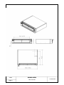
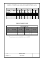
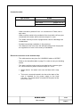
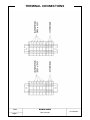
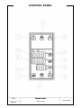
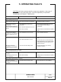
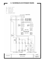
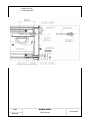
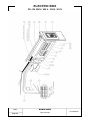
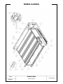
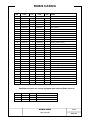
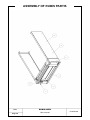
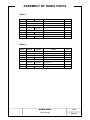
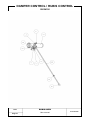
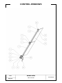
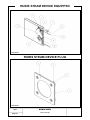
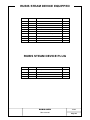
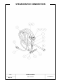
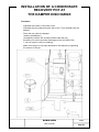
1. GENERAL CHARACTERISTICS
Description:
The range is composed by two ovens:
− R2 oven
2 trays 460 x 660 (18" x 26")
− R4 oven
4 trays 460 x 66 (18" x 26")
The ovens exist with the following variants:
− with a steam device (B version).
− without a steam device (A version).
− stainless steel satin finish.
This range can be combined juxtaposed with the ovens of the TOPAZE range.
The ovens of the RUBIS range are equipped with an electric box on rails
giving ample room in case of repairs.
The Top/Bottom dosing principle makes baking really flexible.
By using a simple dosing button you can apply more or less power at the top
or at the bottom of a particular level. Power can be controlled from 0 to 100%.
RUBIS OVEN
16652
User manual
Page 2
16652
RUBIS OVEN
Page 3
User manual
PL20020284
2. INSTALLATION AND STARTING-UP
Installation :
Check that:
− The doors are sufficiently wide and the room is large enough to
accommodate the ovens,
− The permanent place of installation is able to support the weight of
the oven (cf. chapter 14). The floor must be flat and level (verify
using a spirit level with ruler).
− The room is equipped:
a) with a suitable power supply for the type of oven (minimum power
supply to be complied with),
b) with adequate steam and water inlet and outlet pipes,
c) with an adequate electric insulation system (to be provided by the
customer), see tables on page 5,
d) with suitable ventilation for the equipment installed.
RUBIS OVEN
16652
User manual
Page 4
TABLE OF INTENSITIES AND INSTALLED POWER FOR THE R2 AND R4
TYPE OF RUBIS OVEN
R2A
Voltage
Frequency
R2B
R4A
R4B
Num of
phases
P
(Kw)
I
(A)
P
(Kw)
I
(A)
P
(Kw)
I
(A)
P
(Kw)
I
(A)
208V 60 Hz
3
4
11
5,2
18
7,8
22
9
27
220V 50/60 Hz
3
4,4
12
5,6
19
8,6
23
10
30
230V 50 Hz
3
4,8
13
6,1
20
9,4
24
11
32
380V 50/60 Hz
3N
4,4
8
5,6
13
8,6
14
10
20
400V 50 Hz
3N
4,8
8
6,1
14
9,4
14,5
10
21
415V 50 Hz
3N
5,2
8
6,9
15
10,2
15
12
22
TABLE OF CABLES TO USE
TYPE OF RUBIS OVEN
Volt. Frequ.
R2A
R2B
R4A
4 x 4 mm
2
R4B
208V
4 x 2,5 mm
2
4 x 4 mm
2
4 x 6 mm
2
220V
4 x 2,5 mm
2
4 x 4 mm
2
4 x 4 mm
2
4 x 6 mm
2
230V
4 x 2,5 mm
2
4 x 4 mm
2
4 x 4 mm
2
4 x 6 mm
2
380V
5 x 2,5 mm
2
5 x 2,5 mm
2
5 x 2,5 mm
2
5 x 4 mm
2
400V
5 x 2,5 mm
2
5 x 2,5 mm
2
5 x 2,5 mm
2
5 x 4 mm
2
415V
5 x 2,5 mm
2
5 x 2,5 mm
2
5 x 2,5 mm
2
5 x 4 mm
2
The sections are given for U1000R02V cable or H07RN7.
16652
RUBIS OVEN
Page 5
User manual
Connection table:
Type of oven
Connection (mm)
RUBIS
Water inlet
Copper 10 x 12
Water outlet
Copper 10 x 12
Steam outlet
Diameter 116
− Water inlet with a pressure from 1 to a maximum of 5 bars, with a
stop valve.
− Water overflow outlet to be provided at floor level with a 40 mm pipe
connected to the drain, with a minimum slope of 1 cm/m.
− The steam chimney must be equipped with a drain to discharge the
condensates.
− Provide low and high ventilation in the premises.
− The distance of the oven from the wall and ceiling must comply with
the regulations in force in the country of installation.
Electrical connection to the terminal strip:
− The cable sections are given for U1000R02V cable or H07RN7.
− Refer to the intensities table on page 5, in order to rate your isolating
switch.
− The water overflow outlet must be provided by the customer (pipe
33 x 42 at minimum) with a minimum slope of 1 cm/m.
• Steam device: the water inlet must be fitted with a stop
valve.
• The hood: a terminal located in the box at the back of the
oven is intended for the power supply to the hood
(1A max.). The hood switch is located on the panel at the
front of the oven.
RUBIS OVEN
16652
User manual
Page 6
TERMINAL CONNECTIONS
16652
RUBIS OVEN
Page 7
User manual
PL20020297
2-1
Connection procedure
If the place of installation of the oven corresponds to the recomendations
mentioned above, you can proceed with its connection.
To do this, carry out the following:
− You must be equipped with an circuit breaker and suitable cable.
− Install the circuit breaker then connect the cable.
For safety reasons, the circuit breaker must be switched off.
− Fasten the cable up to the back of the oven.
− Unscrew the cover of the box at the back of the oven.
− Unscrew the left stuffing box and thread the cable through.
− Allow some loose on the cable.
− Strip the wires cleanly.
− Wire according to the diagram opposite page.
− Screw the terminal screws tightly. The wires must not move in their
housings.
− Tighten the stuffing box. Allow some loose on the wires inside the
box.
− Screw back the cover to the electric box.
We advise you to contact our technicians or dealers in case of installation
problems.
RUBIS OVEN
16652
User manual
Page 8
2-2
Starting-up
Refer to chapter 3 before using the oven.
Recommendations for use are given in the description of the controls.
You must dry the cement sole plates of the decks before using the oven. To
do this, procead as follows:
− Half open all the doors. The doors handles must be at centre left
position.
− Switch on the oven by pressing button (1). Turn the temperature
control dial to 100°C/210°F.
− Wait for 2 hours counting from when the green control lamps (on the
controller) switches off.
− Increase the temperature by steps of 50°C/120°F every 2 hours until
reaching 250°C/480°F.
− Wait for 2 hours at 250°C/480°F.
− Your oven is now ready for use.
16652
RUBIS OVEN
Page 9
User manual
2-3
Staring-up
a- Make sure that the oven doors and the steam damper oura are firmly
closed.
b- Switch the main isolating switch normally fitted on your installation to
"ON".
c- Press the ON button about 3 seconds.
d- Turn the level temperature control dial (button 2 and then 3 or 4) to
the temperature required.
e- Your oven is now in preheating mode.
If the operation obtained is not identical to the above we advise you to call our
after sales service, or that of our dealer.
However, in chapter 5 you will find "Operating faults, a troubleshooting guide".
To stop the oven, refer to chapter '"2, End of Work".
RUBIS OVEN
16652
User manual
Page 10
- Page left blank deliberately -
16652
RUBIS OVEN
Page 11
User manual
3. INSTRUCTIONS FOR USE
3-1
Starting work
Before the first baking, the oven must be preheated.
To do this we advise you to use the following method:
− Power up the oven,
− Close the front doors and dampers,
− Select the preheating temperature; it must be higher by 30 to 50
degrees celsius than that for the product to be baked
(see chapter III - 2. Recommendations for use),
− Wait until the temperature has been reached. This is indicated by the
green lamp of the temperature controller which switchess off.
The time taken to reach the temperature is from 40 to 50 minutes, according
to the model of RUBIS oven.
Wait for 10 minutes before the first loading,
− Then, reduce the temperature to that corresponding to the product to
be baked,
− Your oven is ready.
RUBIS OVEN
16652
User manual
Page 12
CONTROL PANEL
16652
RUBIS OVEN
Page 13
User manual
PL20020285
3-2
Use of the electronic control panel
1) Power on, Stop
Prolonged pressing of knob (1) powers up the module. The lamp above
key (1) extinguishes.
The temperature display (A) and the two LED bars light when powered up.
2) Visualising the temperature set-point
The visualised temperature on the LED A is the vault temperature.
The visualised temperature on the LED B is the floor temperature.
A short pression on knob (2) or (5) indicates during 4 seconds the set
temperature of vault or floor.
3) Modifying the Temperature Set-point
Proceed in the same way as for visualisation and as soon as the set-point
measurement is obtained, modify it by using keys (3) and (4) according to
whether you wish to increase it or decrease it.
4) Steam injection
This is done by pressing knob (6), visualised by the lamp above, once.
5) Powering up the Suction Hood
This is done by pressing (7), visualised by the lamp above, once. Pressing it
again stops the suction hood.
RUBIS OVEN
16652
User manual
Page 14
CONTROL PANEL
16652
RUBIS OVEN
Page 15
User manual
PL20020285
6) Using the baking time delay
This function can only be used when the module is switched on
(see chap.1) Switching on).
a - Programming baking time
Pressing the button (8) causes the LED to flash for 5 seconds (MIN).
To adjust cooking time, alter application time in minutes (D) while flashing,
from 1 to 59 minutes using buttons (3) or (4). After 5 second, or another press
on the button (8), the alteration is validated.
b - Countdown of baking time
Press on the Start button (9) and the LED will light up - the time will be
counted down every minute. On reaching 00 minutes, the buzzer rings ; press
on the start button (9) to cut off buzzer and return display (D) to the preceding
time (the cooking timer has no influence on operation of the oven).
7) Using the Clock in Time Delay Mode
Before any programming, enter temperature instruction details and the doses
of the top or botton you wish to obtain at startup of the oven at end of the
baking time delay. The baking time delay function can only be used when the
module is switched off (see paraph.1), with the LED alone (1).
a - Programming the Time Delay
Pressing on button (8) lights up the displays (D) and causes the LED to flash
for 5 seconds (H).
To adjust the time delay, alter display time in hours (D) while flashing, from
1 to 99 hours using buttons (3) or (4).
After 5 seconds, or another press on the button (8), the alteration is validated,
and the display (D) and the LED go out.
b - Countdown of Time Delay
Press on the Start button (9) for 3 seconds, and the display (D) and LED (H)
will light up. The time will be counted down every hour. At 00, the module
switches on, and the oven will heat according to the temperature criteria.
To enter new criteria for a similar time delay, simply press on the start
button (9). To stop a pre-recorded startup programme, switch on by pressing
the button (1).
RUBIS OVEN
16652
User manual
Page 16
Baking time table
(Temperature from 220 to 230°C)
Products (grs)
Baking time (mn)
200
20
250
25
400
30
500
35
These values are given as indications only and can be modified according to the baker's judgement.
• Baking cycle:
As soon as the oven has been preheated, you can load your products. To do
this, we recommend that you:
a- Press the steam injection control button for the required deck,
b- Load the products to be baked into the oven,
c- Inject the steam again according to need,
d- Bake the products,
e- Open the dampers,
f- Remove the products using the Pavailleur loader.
3-3
End of work
− To stop the oven presse switch (1) of the heating control.
We advise you to refer to the following chapter on daily maintenance of the
oven in order to keep it clean and in good working order.
16652
RUBIS OVEN
Page 17
User manual
4. MAINTENANCE
SIMPLE MAINTENANCE: (carried out by the customer)
CAUTION: You must turn the oven off before carrying out any maintenance
operations (except for weekly maintenance).
To do this, use the main switch (1) located on the electric column.
Weekly maintenance:
Clean:
− the inside of the deck,
− the lamp cover,
− the front doors,
− the front of the oven.
Periodic maintenance:
− Check the door seals and replace them if necessary,
− Check the lubrication of the door hinge pins and grease them if
necessary. See chapter "6. List of parts".
OVERALL MAINTENANCE: (carried out by a specialist)
− Replacement of worn parts and adjustment.
− Removal of fur from the steam device.
RUBIS OVEN
16652
User manual
Page 18
CONTROL PANEL
16652
RUBIS OVEN
Page 19
User manual
PL20020285
5. OPERATING FAULTS
CAUTION: the fuses used are rated for normal oven operation. In the case of
a blown fuse or any other faulty part, it must be replaced by an equivalent
Pavailler part (see chapter 7, Sparts parts).
FAULTS
CAUSES
REMEDIES
1) The heating does not work
a/ The power-on lamp is red
(1).
- The power-on knob is not engaged.
- Engage the power-on knob (1).
b/ The control module is
powered up.
The temperature display (A)
and the LED bars (B) and (C)
care lit.
- The temperature control is not
requested.
- Check that the temperature of the setpoint is higher than the baking
temperature.
- The selected temperature is too low.
- The fuses are faulty.
- Switch off the circuit breaker and replace
them.
- The temperature sensor is faulty.
c/ The control module is
powered up. The temperature
display indicates E2 or E2EC.
- Call a Pavailler technician.
d/ The control module is off.
- Switch off the circuit breaker and replace
them.
- The control fuses are faulty.
- The safety thermostat is cut-off.
- Wait for the oven to cool and reset the
safety thermostat. To do it, open the box
and press the red knob located on the
bottom of the box.
The control module is
completely off. You have a
programming clock which is
lit.
- You are in the time delay mode.
- Change the mode on your lock by
switching to baking.
2) The hood lighting does not function.
- The lighting does not
function.
- The fluocompact lamp is faulty.
- Replace the lamp.
- The lighting and the hood
do not function.
- The fuses are faulty.
- Switch off the circuit breaker and replace
the fuses.
3) The steam injection does not function.
The control module is
powered up, you do not have
any steam.
- No water flows through the inlet.
- Check the water in your installation.
RUBIS OVEN
16652
User manual
Page 20
- Page left blank deliberately -
16652
RUBIS OVEN
Page 21
User manual
6. SCHEMA ELECTRIQUE RUBIS
RUBIS OVEN
16652
User manual
Page 22
PL20020291
– Sonde sécurité
– sonde régulation
16652
RUBIS OVEN
Page 23
User manual
PL20020299
7. SPARE PARTS
Electric box R2 - R4 208V / 240 V - 380V / 415V
25-26
Rubis casing
27-28
Assembly of RUBIS parts
29-30
Damper control / RUBIS control
31-32
RUBIS box
33-34
Control windows
35-36
RUBIS steam device equipped
37-38
RUBIS steam device plug
37-38
Steam device connection
39-40
RUBIS OVEN
16652
User manual
Page 24
ELECTRIC BOX
R2 - R4 208V / 240 V - 380V / 415V
16652
RUBIS OVEN
Page 25
User manual
PL20020046
ELECTRIC BOX
R2 - R4 208V / 240 V - 380V / 415V
REP.
CODE
1
00024018
2
3
NAME
380/425V
208/240
Peinted from panel
1
1
02407001
Rubis box black plate
1
1
00033854
Module Top/Bottom
1
1
4
00033005
Channel 60x25
1
1
5
00033502
Circuit-breaker 10x38
7
7
6
00033215
Associated 2 pole kit
2
2
7
00033218
Associated 3 pole kit
1
1
8
00033212
Switch contactor 25A 220V
2
2
1
1
2
9
00030274
Terminal 4mm
10
00033617
Lighting transformator 220-12V
1
1
11
00030331
Rubber funnel D12
1
1
12
00033818
Lamp of bottom G5,3
1
1
13
00033619
Dichro light windows 12V-50W
1
1
14
00033180
Power supply terminal VP
1
1
15
00024259
Rubis beam 220/380V
1
24260 x 1
16
00033384
Thermocouple J
1
1
17
00031259
Adjusting collar
1
1
18
00032047
Knurled nut 6
1
1
19
00032696
Screw 4x15
7
7
20
00032490
Large flat washer 5
4
4
21
03637003
Sym. power rail LG 260
1
1
RUBIS OVEN
16652
User manual
Page 26
RUBIS CASING
16652
RUBIS OVEN
Page 27
User manual
PL20020283
RUBIS CASING
REP.
CODE
QTY
RUBIS 2
CODE
QTY
NAME
RUBIS 4
1
00024071
1
00024073
1
Welded casing
2
00024074
6
00024072
6
Resistor 700W
3
00024496
1
00024490
1
Damper + control
4
00032212
2
00032212
2
Galv. screw TH 6x16
5
00032523
1
00032523
1
Star washer 6
6
01933902
1
01933902
1
Box stop
7
00033362
1
00033362
1
Safety posit. thermostat 340D
8
00024039
1
00024039
1
Equipped box guide
9
00024030
1
00024005
1
Equipped oven floor
10
00033384
1
00033384
1
Thermocouple J L80 LT3280
11
00024088
1
00024088
1
Lighting window
12
00024104
1
00024104
1
Lighting window frame
13
00031335
1
00031335
1
Silicon U section
14
00024069
1
00024069
1
Equipped light reflector
15
00024038
1
00024031
1
Equipped back plate
16
00024013
1
00024013
1
Equipped right rear corner
17
00032702
8
00032702
9
Galv. screw D4 EP 2/2,5 POP
18
02404401
2
02402701
2
Cross corner
19
00032034
13
00032034
15
S. Steel TC L POZI 6 x 16
20
00024044
1
00024027
1
Equipped cross corner
21
00024023
1
00024023
1
Equipped left rear corner
22
00024124
1
00024124
2
Front casing plate 237x670
23
00024126
2
00024126
4
Front casing plate 290x670
24
00024122
1
00024122
2
Front casing plate 160x670
25
02408203
1
02408303
1
Steel cover
26
00024055
1
00024056
1
Slab EP 15MM
27
00032151
2
00032150
9
Stainless steel TC 4x12
28
00024004
1
00024003
3
Equipped HV resistor
29
00032153
4
00032153
4
Stainless steel TC 4x20
30
00032948
1
00032948
2
Galv. nut M6
00021405
1
00021405
1
Needled ceramic fibre 50mm
Modified part when the casing equipped light window (Rubis 2 and 4)
11
00006313
1
Light window
12
00006021
1
Light cone
13
00031350
1
Silicon lamp seal
14
02400106
1
Steel cover LDV
RUBIS OVEN
16652
User manual
Page 28
ASSEMBLY OF RUBIS PARTIS
16652
RUBIS OVEN
Page 29
User manual
PL20020292
ASSEMBLY OF RUBIS PARTS
RUBIS 2
REP.
BLACK
SATIN
NAME
QTY
CODE
1
2
3
4
5
6
7
00024394
Rubis 4 window control
1
00024111
Upper equipped fitting
1
Equipped left box
1
Equipped lower box fitting
1
Right jacket
2
Stainless steel screw
8
Full equipped front
1
00024049
02402401
00024172
00024024
0002402401
00032702
00024199
00024198
RUBIS 4
REP.
BLACK
SATIN
NAME
QTY
CODE
1
00024397
Rubis 4 windows control
1
2
00024094
Upper equipped fitting
1
3
4
5
6
7
00024064
00024067
00024080
00024024
02402401
00032702
00024212
00024210
Equipped left box
1
Equipped lower box fitting
1
Right jacket
2
Stainless steel screw
8
Full equipped front
1
RUBIS OVEN
16652
User manual
Page 30
DAMPER CONTROL / RUBIS CONTROL
00024190
16652
RUBIS OVEN
Page 31
User manual
PL20020286
DAMPER CONTROL / RUBIS CONTROL
00024190
REP.
CODE
1
00010439
Steam dev. seal 70x55x2 TTF
NAME
QTY
1
2
00032006
Stainless steel TH 8x20
4
3
00032524
Galv. star washer AZ 8
4
4
00032600
Mecanindus pin 2x20
1
5
00001715
Machined flap M40
1
6
00001717
Damper flap
1
7
00001718
Damper flap pin
1
8
00032151
Stainless steel screw TC 4x12
2
9
00024116
Black bakelite handle M10 D30 L54
1
10
00024117
Rubis welded Damper cont. L1210
1
11
00030331
Rubber funnel D12
1
RUBIS OVEN
16652
User manual
Page 32
RUBIS BOX
PL20020287
PL20020288
16652
RUBIS OVEN
Page 33
User manual
RUBIS BOX
RUBIS 2 : BLACK code : 00024049
SATIN code : 00024048
REP.
BLACK
SATIN
NAME
QTY
CODE
1
00024119
Rubis box fastening spacer
2
2
00032523
Star washer 6
2
3
00032354
Nut HM 6
2
4
00032040
Stainless steel screw TF HC 4x12
4
5
00032352
Nut HM 4
4
6
00032521
Galv. star washer AZ 4
4
7
00031333
Silicon washer 13x1,5 HT
1
8
00032077
Black s. steel screw TB HC 6x12
2
9
00012427
Chrome left F
1
10
00024076
Left box
1
00024046
RUBIS 4 : BLACK code : 00024064
SATIN code : 00024067
REP.
BLACK
SATIN
NAME
QTY
CODE
1
00024119
Rubis box fastening spacer
2
2
00032354
Nut HM 6
2
3
00032523
Star washer 6
2
4
00032521
Galv. star washer AZ 4
8
5
00032352
Nut HM 4
8
6
00032040
Stainless steel screw TB HC 4x12
8
7
00032077
Stainless steel screw TB HC 6x12
2
8
00031333
Silicon seal 13x1.5 HT
1
9
00012427
Chrome left F
2
10
00024075
Left box
1
00024065
RUBIS OVEN
16652
User manual
Page 34
CONTROL WINDOWS
16652
RUBIS OVEN
Page 35
User manual
PL20020293
CONTROL WINDOWS
REP.
CODE
QTY
RUBIS 2 : 00024394
CODE
QTY
NAME
RUBIS 4 : 00024397
1
00032524
2
Galv. star washer AZ 8
2
00032216
2
Galv. screw TH 8x16
3
00002444
1
Middle bearing Z90
4
00012423
1
Bearing D12 XY
00024133
1
Left door hinge pin
00024132
1
Right door hinge pin
5
00024136
1
6
7
00012425
1
00012425
2
Forked pin XY
8
00012422
1
00012422
1
Bearing D20 XY
9
00032607
2
00032607
4
Mecaninidus pin 3x20
10
00032503
2
00032503
4
Galv. flat washer ZU 8
11
00032913
1
00032913
2
Screw CHC 8x35
12
00024116
1
00024116
2
Black bakelite handle M10 D30 L54
13
00024084
1
00024084
2
Rubis window EP 6MM
14
00034046
2
00034046
4
Knurled nut M6 EP9
15
00024033
1
00024033
2
Rubis window clamp
16
00002558
2
00002558
2
Door sect. set collar D20
17
00032325
2
00032325
2
Screw ST HC 6x6 B-tray
18
00024032
1
00024032
2
Forked + pin CMDE
RUBIS OVEN
16652
User manual
Page 36
RUBIS STEAM DEVICE EQUIPPED
PL20020289
RUBIS STEAM DEVICE PLUG
PL20020290
16652
RUBIS OVEN
Page 37
User manual
RUBIS STEAM DEVICE EQUIPPED
REP.
CODE
1
00032182
Brass washer MU 8 x 18
NAME
QTY
8
2
00032172
Brass nut HU 8
8
3
00024050
Rubis steam device connection tube
1
4
00001955
Rubis top steam device seal
2
5
00024012
Rubis steam device
1
6
00024142
Rubis steam device injector
1
7
00031014
Union F 10/12 x G1/2 body
1
8
00024386
Sili glass sheath D10 L100
2
9
00187505
Water tank pin
1
10
00002003
Steam device resistor 1400 W
1
RUBIS STEAM DEVICE PLUG
REP.
CODE
NAME
QTY
1
00180041
Rubis top steam coverseal
1
2
00032172
Brass nut HU 8
4
3
00032182
Brass washer MU 8x18
4
4
00001955
Rubis top steam device seal
1
RUBIS OVEN
16652
User manual
Page 38
STEAM DEVICE CONNECTION
16652
RUBIS OVEN
Page 39
User manual
PL20020294
STEAM DEVICE CONNECTION
REP.
CODE
CODE
NAME
QTY
MODULE 2
MODULE 4
1
00024145
00024145
Steam device equipped overflow
1
2
00024143
00024144
Electrovalve equipped tube
1
3
00031070
Equal T 10/12
1
4
00024147
Rubis waste water discharge
1
5
00031019
Adjusting nut 10/12
1
6
00031050
Copper connection stop plug
1
7
00031254
Electrovalve sim. 220 V 50/60 HZ
1
8
00024189
Rilsan tube 10/12 LG100
1
9
00031033
Special male union 12x3/8
1
10
00032051
Galv. nut HM 4
1
11
00032115
Galv. screw TC 4x20
2
12
00032521
Galv. star washer AZ 4
6
13
00032265
Galv. screw TC 4x8
2
14
00033475
Temperature controller 350 D Fl
1
15
00031202
Washing Machine Hose 3/4 2.5 M
1
RUBIS OVEN
16652
User manual
Page 40
8. ACCESSORIES AND OPTIONS
− RUBIS 2 increasing kit
− RUBIS 4 increasing kit
− Installation of a condensate recovery pot at the damper discharge
16652
RUBIS OVEN
Page 41
User manual
INSTALLATION OF A CONDENSATE
RECOVERY POT AT
THE DAMPER DISCHARGE
Procedure
− Withdraw the bottom of the lower oven
− Withdraw the plug obstructing the side of the T joint located near the
damper
− Place the pot under the damper
(seal the pot/damper)
(completely unscrew the screws located under the pot)
− Screw the nut on the pot tube discharge on the free side of the
T (do not forget to carry out sealing)
− Make sure the pot is securely fastened on the damper by tightening
the screws of the pot
RUBIS OVEN
16652
User manual
Page 42
DEALER'S STAMP