1
AVERSIVE STIMULATION WITH
VIDEO MONITORING
USERS MANUAL
SOF-732-4 User’s Manual
DOC-155
Rev. 1.0
Copyright © 2007
All Rights Reserved
MED Associates, Inc.
P.O. Box 319
St. Albans, Vermont 05478
www.med-associates.com
MED ASSOCIATES INC.
AVERSIVE STIMULATION WITH VIDEO MONITORING
- ii -
MED ASSOCIATES INC.
AVERSIVE STIMULATION WITH VIDEO MONITORING
TABLE OF CONTENTS
Chapter 1 ........................................................................................................ 1
Introduction ..................................................................................................... 1
Overview ...................................................................................................... 1
Background................................................................................................... 1
Hardware...................................................................................................... 2
Software....................................................................................................... 2
Chapter 2 ........................................................................................................ 3
Aversive Stimulation with Video Monitoring Software .............................................. 3
Aversive Stimulation Control ............................................................................ 3
Video Monitor Communication.......................................................................... 4
Aversive Stimulation with Video Monitoring Components ...................................... 4
Chapter 3 ........................................................................................................ 5
Software Installation.......................................................................................... 5
Single Computer System Installation Procedure .................................................. 6
Two Computer System Installation Procedure..................................................... 7
Chapter 4 ........................................................................................................ 9
Setting Up Aversive Stimulation with Video Monitoring ............................................ 9
Video Monitor Configuration ............................................................................ 9
MED-PC Configuration .................................................................................. 11
MED-PC Display ........................................................................................... 14
Chapter 5 ...................................................................................................... 17
Running the Experiment ................................................................................... 17
Issue Start Command ................................................................................... 17
Stopping Experiment Before Reaching Maximum Current ................................... 17
Chapter 6 ...................................................................................................... 19
Video Playback and Analysis ............................................................................. 19
Chapter 7 ...................................................................................................... 20
Using Open Session Dialog Instead of Wizard ...................................................... 20
Chapter 8 ...................................................................................................... 22
Using a Macro ................................................................................................. 22
- iii -
MED ASSOCIATES INC.
AVERSIVE STIMULATION WITH VIDEO MONITORING
Chapter 9 ...................................................................................................... 23
Troubleshooting .............................................................................................. 23
No Session Parameters ................................................................................. 23
USER INPUT ERROR Message ........................................................................ 24
- iv -
MED ASSOCIATES INC.
AVERSIVE STIMULATION WITH VIDEO MONITORING
CHAPTER 1
Introduction
Overview
Aversive Stimulation with Video Monitoring allows the user the ability to use MED-PC,
Video Monitor, and Aversive Stimulation testing equipment to record aversive reaction in
lab animals.
Background
Researchers at a large university wanted to determine the average minimum current
necessary to cause an aversive reaction in mice. These researchers used an aversive
stimulation cage connected to a MED Associates ENV-414S Aversive Stimulator with
Scrambler. While one researcher would operate the output current dial on the ENV-414S,
trying to maintain a consistent 10µA rise every 5 seconds, a second researcher would
visually monitor the test subject through the SAC peephole for an aversive reaction to
the current stimulus.
It was determined that there are several problems with this method that could be solved
using other MED Associates hardware and software. First, maintaining a consistent
current increase is much easier using MED-PC to communicate with an ENV-413 Aversive
Stimulator and ENV-412 Scrambler. Second, using a Video Monitor camera in place of a
human eye allows for a more comfortable testing situation, allows multiple researchers to
confer over the subject animal’s reactions, and provides the ability to rewind and review
the animal’s reactions. MED Associates Aversive Stimulation with Video Monitoring
provides all of these features.
- 1 -
MED ASSOCIATES INC.
AVERSIVE STIMULATION WITH VIDEO MONITORING
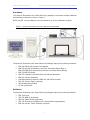
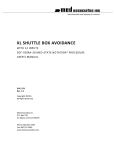
Hardware
The Aversive Stimulation with Video Monitoring package incorporates multiple hardware
and software components, shown in Figure 1.
NOTE: do NOT connect hardware until instructed by its driver installation program.
Figure 1 - Aversive Stimulation with Video Monitoring Components
The Aversive Stimulation with Video Monitoring Package requires the following hardware:
•
•
•
•
•
•
•
•
•
ENV-008-FPU Quick Change Test Chamber
ENV-005-QD Quick Disconnect Grid Floor Connection Block (Rat) or
ENV-005A-QD Quick Disconnect Grid Floor Connection Block (Mouse)
DIG-729 USB Controller
ENV-413 Computer Controlled Aversive Stimulus Generator
ENV-412 Current Scrambler
Interface Cabinet (houses the ENV-413 and ENV-412 cards)
ENV-420 Current Tester (optional)
Sound-Attenuating Cubicle
PC with peripherals
Software
The Aversive Stimulation with Video Monitoring Package requires the following software:
•
•
•
•
•
DIG-729 Driver
SOF-735 MED-PC application
SOF-842 Video Monitor application
SOF-732-4 Aversive Stimulation with Video Monitoring application
ENV-420 Current Tester Software (optional)
- 2 -
MED ASSOCIATES INC.
AVERSIVE STIMULATION WITH VIDEO MONITORING
CHAPTER 2
Aversive Stimulation with Video Monitoring Software
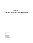
Aversive Stimulation with Video Monitoring (AvStimVideo) is a MED-PC MedState Notation
(MPC) program with two main responsibilities:
•
Control the current to the aversive stimulation chamber grid floor.
•
Communicate with the Video Monitor software.
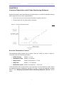
Figure 2 - Aversive Stimulation Model
Aversive Stimulation Control
The AvStimVideo MPC program runs a simple “ramp up” model, as shown in Figure 2.
The model uses the following parameters:
•
Initial Current
default = 0.0 µA
•
Acclimation Time
default = 5 seconds
•
Step Current
default and minimum = 2.5 µA
•
Step Time
default = 1.25 seconds
•
Maximum Current
default and maximum = 1000.0 µA
The AvStimVideo MPC program allows early termination of the stimulation model, before
the maximum current is reached by issuing a “K” pulse. This will be explained in greater
detail in the “Stopping Experiment Before Reaching Maximum Current” section
below.
- 3 -
MED ASSOCIATES INC.
AVERSIVE STIMULATION WITH VIDEO MONITORING
Video Monitor Communication
The AvStimVideo MPC program:
•
Opens communication with Video Monitor using the MED / Video Monitor
Interface.
•
Sends a “Start Camera” command to a camera waiting in Video Monitor. The
command travels via the communication pipe to begin saving a video file (*.WMV
or *.MEV).
•
Sends annotation messages at each aversive stimulation current step to appear
as captions on the saved video.
•
Sends a “Stop Camera” command at end of Aversive Stimulation program, or
when terminated early by user input, to end the video file saving.
•
Closes the MED / Video Monitor interface communication channel.
Aversive Stimulation with Video Monitoring Components
AvStimVideo is comprised of 4 software files:
•
AvStimVideo.MPC – MedState Notation code compiled using TransIV and run using
MED-PC. The code controls the ENV-413 Aversive Stimulator, and communicates
with Video Monitor.
•
AvStim_spt.HED, .BOD – Delphi Pascal code used by AvStimVideo.MPC to parse
the computer and camera name from the MED-PC session comment field.
•
AvStimSample.MAC – MED-PC macro code to simplify loading AvStimVideo,
entering computer and camera names, and sending start command to MED-PC. A
macro file is an optional step. However, creating a macro file for each testing
scenario will greatly improve efficiency, and is good practice to help define
reliable and repeatable experiments.
- 4 -
MED ASSOCIATES INC.
AVERSIVE STIMULATION WITH VIDEO MONITORING
CHAPTER 3
Software Installation
Aversive Stimulation with Video Monitoring may be configured to operate on a single
computer or two networked computers. In the single computer system, the three major
software components – Video Monitor, MED-PC IV, and Aversive Stimulation with Video
Monitoring – are all installed on the same computer. In the two-computer setup, MED-PC
IV and Aversive Stimulation with Video Monitoring software are installed onto one
computer, and Video Monitor on the other. However, due to the network security issues,
running on multiple computers may be difficult to configure. It is recommended that
MED-PC IV, Aversive Stimulation with Video Monitoring, and Video Monitor all be installed
on a single computer.
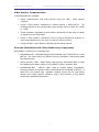
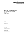
Figure 3 – Single Computer vs. Two Computer Setup
The main difference between the single and two-computer system installation procedures
is the extra step of installing the “Video Monitor MED-PC Interface” on the MED-PC
computer of the two-computer system. In the single computer setup, the Video Monitor
MED-PC Interface is installed as part of the Video Monitor installation process.
Table 1 - Installation order
Single Computer System
Two Computer System
MED-PC IV Computer
1.Install MED-PC IV
1.Install MED-PC IV
2.Install Video Monitor
2.Install Video Monitor MEDPC Interface
3.Install AvStim
3.Install AvStim
- 5 -
Video Monitor Computer
4.Install Video Monitor
MED ASSOCIATES INC.
AVERSIVE STIMULATION WITH VIDEO MONITORING
Single Computer System Installation Procedure
The single computer system is the recommended configuration to avoid network
communication difficulties. The installation order is as shown in the leftmost column of
Table 1 above (Note: steps 2 and 3 may be performed in reverse order):
1. Install MED-PC IV. Refer to the MED-PC IV User’s Manual for details.
2. Install Video Monitor. Refer to the Video Monitor User’s Manual for details. In
addition to installing the Video Monitor program, this installation procedure will install
the Video Monitor MED-PC Interface components into the MED-PC IV folder. The
installation procedure will search for the MED-PC IV installation directory, and
automatically install the interface components there. If the installation program is
unable to find MED-PC IV, the Interface components will not be installed. The Video
Monitor MED-PC Interface component installation will put the MED_VM_Interface.DLL
and VM_Iface.HED files in the MED-PC IV installation directory, the VIDEO.MPC file in
the MED-PC IV\MPC folder, and insert {$I VM_IFACE.HED} into the User.PAS file.
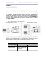
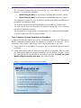
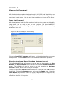
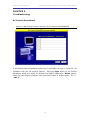
3. Install Aversive Stimulation with Video Monitoring. Insert the Aversive Stimulation
with Video Monitoring distribution CD into the computer. The screen shown in Figure
4 will appear. If this screen does not appear, use Windows Explorer to browse to the
CD drive and double click the “Autorun.EXE” file.
Figure 4 - Aversive Stimulation with Video Monitoring Main Screen
Click To install the software click here, and then click the Next button at each
successive screen to choose the default installation settings.
The installation will search for the MEDPC_IV.EXE file to determine the MED-PC IV
installation directory. If the installation program cannot find the MEDPC_IV.EXE file,
a prompt will appear to browse to the program. Choose Yes when prompted to
install to the found MED-PC IV directory.
- 6 -
MED ASSOCIATES INC.
AVERSIVE STIMULATION WITH VIDEO MONITORING
The installation program will alter the User.PAS file in the MED-PC IV installation
directory. Two lines will be inserted:
•
{$I AVSTIM_SPT.HED} in the {Place $I Filename.HED files here.} section.
•
{$I AVSTIM_SPT.BOD} in the {Place $I Filename.BOD files here.} section.
The installation program will copy the AvStim_Spt.BOD and AvStim_Spt.HED files to
the MED-PC IV installation folder.
The program then copies the AvStimVideo.MPC file to the MED-PC IV\MPC folder.
The user manual “Aversive Stimulation with Video Monitoring.PDF” will be copied to
the MED-PC IV\Manuals directory.
The last code file to be copied will be a sample macro file, called AvStimSample.MAC.
It will be copied to the MED-PC IV\Macro folder.
Two Computer System Installation Procedure
If MED-PC IV and Video Monitor are running on separate computers, the Video Monitor
MED-PC Interface components must be installed on the MED-PC IV computer. This is
explained in Step 2 below. Note: steps 2 and 3 may be performed in any order.
1. Install MED-PC IV on the MED-PC IV computer, refer to the MED-PC IV User’s Manual
for details.
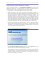
2. Install Video Monitor MED-PC Interface on the MED-PC IV computer. This will install
the Video Monitor MED-PC Interface components into the MED-PC IV folder. Insert
the Video Monitor CD into the MED-PC IV machine, and click To install the Video
Monitor MED-PC interface click here. See Figure 5 below.
Figure 5 - Video Monitor MED-PC Interface Installation
- 7 -
MED ASSOCIATES INC.
AVERSIVE STIMULATION WITH VIDEO MONITORING
The installation program will search for the MED-PC IV program installed in step 1.
Choose Yes when prompted to install to the found MED-PC IV directory. The install
program will put the MED_VM_Interface.DLL and VM_Iface.HED files in the MED-PC
IV directory, and VIDEO.MPC in the MED-PC IV\MPC folder. The installation program
will then insert {$I VM_IFACE.HED} into the User.PAS file.
3. Install Aversive Stimulation with Video Monitoring. See step 3 in the Single Computer
System Installation Procedure above.
4. Install Video Monitor on the Video Monitor computer. Refer to the Video Monitor
User’s Manual for details. This step may be performed at any time in relation to the
first three steps.
In the two-computer system, the MED-PC IV computer must have “write file”
permissions on the Video Monitor computer. It is recommended that both computers
be a part of the same domain. See your network administrator for details. Again, the
single computer system is recommended to avoid this possible problem.
- 8 -
MED ASSOCIATES INC.
AVERSIVE STIMULATION WITH VIDEO MONITORING
CHAPTER 4
Setting Up Aversive Stimulation with Video Monitoring
To use Aversive Stimulation with Video Monitoring, both MED-PC and Video Monitor
components must first be configured. MED-PC and Video Monitor may be running on
separate computers. In the example below, MED-PC is running on a computer named
“med-pc” and the Video Monitor computer is named “testxp”.
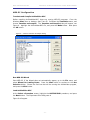
Video Monitor Configuration
Find Computer Name
In Aversive Stimulation with Video Monitoring, MED-PC needs to be told the name of the
Video Monitor computer. If MED-PC and Video Monitor are running on the same
computer, the computer name is “.”.
In a two-computer system, to find the Video Monitor computer name:
1. Open to the Start menu,
2. Right-click on My Computer,
3. Choose Properties,
4. Click the Computer Name tab.
The computer name is the text before the first period in the “Full computer name” field.
See example in Figure 6. The computer name here is “testxp”. Leave off the domain
information (.car.inavt.us) when specifying this computer in the MED-PC session
comments field.
Figure 6 - Finding Computer Name: “testxp”
- 9 -
MED ASSOCIATES INC.
AVERSIVE STIMULATION WITH VIDEO MONITORING
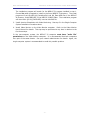
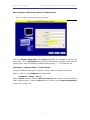
Setup Camera in System Settings Dialog
Figure 7 - Video Monitor System Settings Dialog
To configure Video Monitor, start the application, and bring up the System Settings
dialog. Navigate to the desired camera in the camera tree. In Figure 7, the camera
being used is “SAC-1”. Fill the checkbox in the “On/Off” field to activate the camera
display, and fill the checkbox in the “Save Video” field. Next choose the “Remote
(MED PC, e.g.)” option of the “Trigger” field to tell the camera not to start saving until
commanded by MED-PC.
Close the System Settings Dialog
Last, press the OK button. The System Settings dialog will close, and the SAC-1 camera’s
video stream will be displayed in a window titled “Camera: SAC-1
Waiting for
remote trigger…” Adjust the camera features settings now to show a bright, clear
image.
- 10 -
MED ASSOCIATES INC.
AVERSIVE STIMULATION WITH VIDEO MONITORING
MED-PC Configuration
Translate and Compile AvStimVideo.MPC
Before compiling AvStimVideo.MPC, close any running MED-PC programs. From the
Windows Start menu or desktop, start Trans IV. Pull down the Translation menu, and
choose Translate and compile. The Translate and Compile dialog will appear, see
Figure 8. Highlight the AvStimVideo.MPC file, and press the Make button. Next press
the OK button.
Figure 8 - TransIV Translate & Compile dialog
Run MED-PC Wizard
Start MED-PC. If the Wizard does not automatically appear, go to the File menu, and
select Wizard for Loading Boxes. Press the Next button to continue to the Box
Selection dialog. Choose the first box that will be running the AvStimVideo program,
and press the Next button.
Load AvStimVideo.MPC
At the Select a Procedure screen, highlight the AVSTIMVIDEO procedure, and press
the Next button. The Experiment Info dialog seen in
Figure 9 will appear.
- 11 -
MED ASSOCIATES INC.
AVERSIVE STIMULATION WITH VIDEO MONITORING
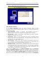
Enter computer and camera names in Comments field
Figure 9 - MED-PC Wizard Experiment Info Screen
Enter the Subject, Experiment, and Group parameters as necessary to identify the
experiment. In the Comments field, type the Video Monitor computer name and the
camera name, each surrounded by double quotation marks (“). The format will be:
Comments: “Computer Name” “Camera Name”
Using the computer name seen in Figure 6: “textxp”, and the camera name seen in
Figure 7: “SAC-1”, the Comments field should read:
Comments: “testxp” “SAC-1”.
Press the Next button to show the Review Choices screen and be sure the Comments
field is filled correctly. Press the Next button to continue to the Session Parameters
screen seen in Figure 10.
- 12 -
MED ASSOCIATES INC.
AVERSIVE STIMULATION WITH VIDEO MONITORING
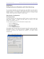
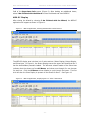
Figure 10 - MED-PC Wizard Session Parameters Screen
Enter Session Parameters
At the Session Parameters screen, the Aversive Stimulation Ramp Up Model
parameters default values are displayed. Refer to Figure 2 for a graphical representation
of the Ramp Up model.
•
Cage Acclimation – default = 5.0 seconds. Cage Acclimation is the time, in
seconds, which the Initial Shock is applied to the grid floor before increasing.
•
Step Duration – default = 1.25 seconds.
between each successive rise in current.
•
Initial Shock – default = 0.0 µA. Initial Shock is the current, in microamps, flowing
through the grid floor at the experiment start. The Initial Shock current lasts for the
time specified in the Cage Acclimation field.
•
Step Increment – default 2.5 µA. Step Increment is the amplitude of each current
rise, in microamps. The minimum resolution of the ENV-413 is 2.5 µA, therefore, the
minimum value allowed for the Step Increment variable is 2.5 µA.
•
Maximum Current – default 1000 µA. Maximum Current is the absolute highest
current amperage that will flow through the grid floor. 1000 microamps is equivalent
to 1 milliamp. The experiment will end and the video camera commanded to stop
saving video when the maximum current is reached.
Step Duration is the time, in seconds,
After pressing the Next button on the Session Parameters screen, the Load More
Boxes or Send Start Command? Wizard screen will appear. Before issuing the Start
Command, load any other boxes by repeating the above steps starting at choosing which
box to load. Choose I Want to Load More Boxes and the Wizard will take you there.
Be sure to enter the correct computer and camera name for each box in the Comments
- 13 -
MED ASSOCIATES INC.
AVERSIVE STIMULATION WITH VIDEO MONITORING
field of the Experiment Info screen (Figure 9). After loading any additional boxes,
select I Am Finished with the Wizard to close the Wizard and show MED-PC.
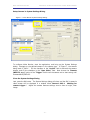
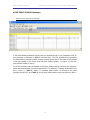
MED-PC Display
After closing the Wizard by choosing I Am Finished with the Wizard, the MED-PC
application will appear as shown in Figure 11.
Figure 11 - MED-PC Application, Showing AvStimVideo Loaded in Box 1
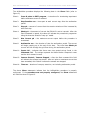
The MED-PC display area is broken into 3 main sections: Status Display, Output Display,
and Show Area. In Figure 11, the Status Display area at the upper left shows that Box 1
has the AvStimVideo procedure loaded. The left-most column header of the Show Area
indicates that the shows are from All Boxes, and shows one through five can be seen
for each box. Click the All Boxes column header to cycle through the boxes. The first
click will alter the Show Display to present all the Shows for Box 1. See Figure 12.
Figure 12 - MED-PC Application, Displaying Box 1’s "Show" Statements
- 14 -
MED ASSOCIATES INC.
AVERSIVE STIMULATION WITH VIDEO MONITORING
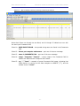
The AvStimVideo procedure displays the following data in the Show fields (refer to
Figure 2):
Show 1:
Issue K pulse to EXIT program – instructions for terminating experiment
before maximum current is reached.
Show 2:
Step Duration sec – time spent at each current step, after the acclimation
period.
Show 3:
Step µA – amount of current that the aversive stimulus will be increased by
with each step.
Show 4:
Shock µA – the amount of current the ENV-413 is set to transmit. After the
Start Command is issued, this value will indicate the procedure’s progression
along the Aversive Stimulus “ramp up” model.
Show 5:
Max Current µA – the maximum current output before the procedure is
terminated.
Show 6:
Acclimation sec – the duration of time the acclimation period. The current
will begin ramping up at the end of this time. The initial base Shock µA
current will flow through the grid floor during this acclimation period.
Show 11: Inputs OK – indicates that there were two quoted strings found in the
Comments field. The strings represent the Video Monitor computer’s name
and the box’s camera’s name.
Show 12: Camera Started / Camera Stopped – after the Start command this field
will indicate the camera has started. After a K pulse or maximum current has
been exceeded, this field will indicate the camera was stopped.
Show 14: Time sec – duration of ramp up execution, not including acclimation period.
The above Show statements indicate that the AvStimVideo procedure is properly
configured. If the procedure was not properly configured, the Show statements
will look like those in Figure 13.
- 15 -
MED ASSOCIATES INC.
AVERSIVE STIMULATION WITH VIDEO MONITORING
Figure 13 - MED-PC Display indicating missing Comments parameters
Notice that Shows one through ten are blank, and 11 through 15 indicate an error with
the user input Comments field.
Show 11: USER INPUT ERROR – two quoted strings were not found in the Comments
field.
Show 12: Please put computer and camera – part one of the error message.
Show 13: name in COMMENTS field – part two of the error message.
Show 14: usage: “Computer” “Camera” – proper usage of the Comments field to
indicate the Video Monitor Computer and Camera.
Show 15: e.g. “.” “Cam1” – example of proper Comments field usage, indicating that
Video Monitor is running on the same computer as MED-PC (“.”), and the
camera name is “Cam1”.
- 16 -
MED ASSOCIATES INC.
AVERSIVE STIMULATION WITH VIDEO MONITORING
CHAPTER 5
Running the Experiment
After the AvStimVideo procedure has been loaded by MED-PC IV, and Video Monitor has
a video window titled “Camera: SAC-1
Waiting for remote trigger…”, the
experiment is ready to start. Now is a good time to load the test animals into the boxes.
Issue Start Command
After the animals are loaded, the SACs are closed, and the video streams are checked for
image quality, you are ready to start the test procedure. Pull down the MED-PC
Configure menu, and choose the Signals option. The Send Signals to Boxes dialog
will appear (Figure 14).
Figure 14 - MED-PC Send Signals to Boxes Dialog
Choose the Issue START Command radio button, and select the Boxes that are running
the experiment. Press the Issue button to start the Aversive Stimulation procedure.
Stopping Experiment Before Reaching Maximum Current
The AvStimVideo MPC code will increase the current at a rate determined by the Step
Duration and Step Increment values specified in the Wizard’s Session Parameters
screen. The procedure will stop the current to the grid floor when the Maximum
Current is reached, and the video saving will be stopped.
To stop the experiment before the maximum current is achieved, issue a “K” pulse to
the box(es). Pull down the Configure menu, and choose the Signals option. Select the
Issue K Pulse option, set the number of K pulses to 1, and choose the boxes you wish
to stop. Press the Issue button to send the K Pulse. The shock current will be turned
off, and the video file will stop saving.
- 17 -
MED ASSOCIATES INC.
AVERSIVE STIMULATION WITH VIDEO MONITORING
NOTE: If the AvStimVideo procedure is stopped without first issuing a K pulse, the shock
will continue for up to one minute. Also, the video file will continue recording. So
do not end the procedure early by using the “Close Session” command, or shut down
MED-PC without first sending a K pulse to the box running the procedure. If this does
happen, go to Video Monitor and close the video window to stop recording. To stop the
shock, unplug the ENV-412 to ENV-413 connection, or turn off the power to the rack
containing the ENV-412 and ENV-413.
- 18 -
MED ASSOCIATES INC.
AVERSIVE STIMULATION WITH VIDEO MONITORING
CHAPTER 6
Video Playback and Analysis
After the maximum current has been reached, or a K pulse was issued, the AvStimVideo
procedure will end. The ENV413 will stop transmitting current to the grid floor, and the
Video Camera will stop saving video. Now it is time to analyze the saved video using the
Video Monitor Playback tool. Go to Video Monitor, close the camera window, pull down
the Video Monitor File menu and choose Open. Select the video that was just created
by the AvStimVideo procedure in the File Open dialog, and press the OK button.
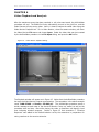
Figure 15 - Video Monitor Playback Dialog
The Playback window will appear as in Figure 15. Notice that the AvStimVideo procedure
has sent the Video Monitor program an annotation. The annotation in the above example
reads “0:00:27.466 – Current = 55.000 µA”. The AvStimVideo procedure sends a
similar message at each step of the Aversive Stimulus “ramp up” model, as well as the
procedure start and stop. Now while playing the video, a researcher can identify visual
cues indicating stimulus response. Notice in Figure 15 that annotation 7 “Stimulus
Response” was added to the Default behavior set by the researcher in preparation for
noting reactions to the aversive stimulus.
- 19 -
MED ASSOCIATES INC.
AVERSIVE STIMULATION WITH VIDEO MONITORING
CHAPTER 7
Using Open Session Dialog Instead of Wizard
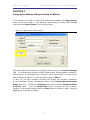
If the Wizard is not used for loading the AvStimVideo procedure, the Open Session
dialog can be used instead. To use the Open Session dialog, pull down MED-PC’s File
menu and choose Open Session. See Figure 16 below.
Figure 16 - MED-PC Open Session Dialog
Enter the Video Monitor computer name and the camera name in the Session Comment
field. The AvStimVideo procedure will NOT WORK without these parameters encased in
double quotes. The example shown in Figure 16 shows Video Monitor is running on the
same computer as MED-PC (“.”) and the camera name is “SAC-1”.
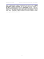
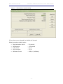
To alter the five input variables controlling step height, step duration, acclimation
current, acclimation period, and maximum current, use the Change Named Variables
Dialog (Figure 17). Pull down the Configure menu, and choose the Change Variables
(CTRL+A) option. Press the Named Vars button to display the five procedure
variables. After making changes, press the Issue button to finalize the edits. Press the
Close button to dismiss the dialog.
- 20 -
MED ASSOCIATES INC.
AVERSIVE STIMULATION WITH VIDEO MONITORING
Figure 17 - Change Named Variables Dialog
If the values are not changed, the defaults will be used.
Default procedure variable values:
•
Cage Acclimation Period
- 5.0 seconds
•
Step Duration
- 1.25 seconds
•
Initial Shock
- 0.0 µA
•
Step Increment
- 2.5 µA
•
Maximum Current
- 1000 µA (1 milliamp)
- 21 -
MED ASSOCIATES INC.
AVERSIVE STIMULATION WITH VIDEO MONITORING
CHAPTER 8
Using a Macro
Loading boxes and setting experiment parameters can be simplified by using macro
files. MED-PC can store and playback commands stored in a *.mac text file. Macro files
can be edited using any text editor (e.g. Notepad) or using the MED-PC macro editor
(Macros menu, Editor option).
Aversive Stimulation with Video Monitoring
AvStimSample.mac, shown in Figure 18 below.
ships
with
a
sample
macro
file:
Figure 18 - Sample Macro File
LOAD BOX 1 SUBJ 0 EXPT 0 GROUP 0 PROGRAM AvStimVideo
COMMENT BOX 1 "ComputerName" "CameraName"
START BOXES 1
Reading line-by-line, the macro file:
1. Loads the AvStimVideo procedure into box 1.
2. Creates Session Comment for box 1: “ComputerName” “CameraName”
3. Starts the AvStimVideo procedure in box 1.
Using this macro file as a starting point, change “ComputerName” to be the name of the
Video Monitor Computer, and “CameraName” to the name Video Monitor uses to define
the camera in box 1. The computer name and camera name must each be
surrounded by double quotes (“x”). Save the file as a unique name in the C:\MEDPC IV\Macro folder. Note: the name of the MED-PC IV installation folder may be
different on the MED-PC computer.
To use the macro file, configure Video Monitor so the camera is waiting for the start
trigger from MED-PC, then start MED-PC and cancel the Wizard if it appears. In MED-PC,
pull down the Macros menu, and choose Play Macro…. Select the file saved in the
C:\MED-PC IV\Macro folder, and click OK.
Using the macro file, the AvStimVideo procedure will use the default values for the five
input parameters. If values other than the defaults are desired, remove line 3 from the
macro: START BOXES 1. Save and run the macro. Now use the Change Named
Variables Dialog (Figure 17) to edit the procedure variables before manually issuing
the START command.
NOTE: when using a two-computer system, the START BOXES command may need to be
delayed to compensate for network communication lag. Simply insert a line before the
START BOXES 1 command such as “DELAY 1000” (without the quotes), which will pause
for 1 second (1000 milliseconds).
- 22 -
MED ASSOCIATES INC.
AVERSIVE STIMULATION WITH VIDEO MONITORING
CHAPTER 9
Troubleshooting
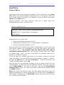
No Session Parameters
Figure 19 - MED-PC Wizard Session Parameters Screen Showing NO PARAMETERS
If the Wizard Session Parameters screen has no information as seen in Figure 19, the
Comments field was not properly entered. Press the Close button on the Session
Parameters dialog and restart the Wizard from MED-PC (File menu, Wizard option).
Enter the Video Monitor computer name and camera name in double quotes. E.g. “.”
“SAC-1”.
- 23 -
MED ASSOCIATES INC.
AVERSIVE STIMULATION WITH VIDEO MONITORING
USER INPUT ERROR Message
Figure 20 User Input Error Message
If the AvStimVideo procedure cannot find two quoted strings in the Comments field, an
error message is displayed in MED-PC’s Shows area. The first quoted string represents
the Video Monitor computer name, and the second quoted text is the name of the camera
in the box named in the Shows area left-most column header. In Figure 20, the leftmost column header is “Box 1”.
To fix this problem, start the Wizard or the Open Session dialog, and enter the computer
name and camera name in the Comments field. For example, if loading AvStimVideo into
Box 1, enter: “.” “SAC-1”, where “.” indicates Video Monitor is running on the same
computer as MED-PC, and “SAC-1” is the name Video Monitor calls the camera in Box 1.
- 24 -