1
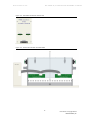
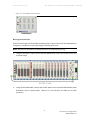
instrumentation and software for research
XL SHUTTLE BOX AVOIDANCE
WITH 12 INPUTS
SOF-700RA-30 MED-STATE NOTATION® PROCEDURE
USER’S MANUAL
DOC-274
Rev. 1.0
Copyright ©2013
All Rights Reserved
Med Associates Inc.
P.O. Box 319
St. Albans, Vermont 05478
Phone: 802.527.2343
Fax: 802.527.5095
www.med-associates.com
SOF-700RA-30, SHUTTLE BOX AVOIDANCE 12 INPUTS
notes
i
SOF-700RA-30, SHUTTLE BOX AVOIDANCE 12 INPUTS
Table of Contents
Chapter 1 | Introduction ................................................................................................ 1
System Requirements ................................................................................................................... 1
Chapter 2 | Hardware ..................................................................................................... 2
Hardware Guide............................................................................................................................. 2
Wiring Instructions........................................................................................................................ 5
Hardware Test Procedure .......................................................................................................... 12
Input Card / IR Beams ............................................................................................................... 13
Chapter 3 | Software .................................................................................................... 14
Software Installation................................................................................................................... 14
Backing up the Software ............................................................................................................ 14
Hardware Configuration Utility .................................................................................................. 14
Chapter 4 | Beginning & Running an Experiment .................................................. 15
Translating MED-PC (.mpc) Files .............................................................................................. 15
Using the MED-PC IV Load Wizard ........................................................................................... 15
Viewing/Changing Variable Values ........................................................................................... 22
Chapter 5 | Understanding the Data Files................................................................ 24
Sample Data File ......................................................................................................................... 24
Chapter 6 | Data Analysis – Using MED-PC to Excel .............................................. 26
Using a Pre-Formatted Table Profile (.MTP file) ..................................................................... 26
Editing the .MTP file.................................................................................................................... 29
Appendix A | Contact Information............................................................................. 30
ii
MED ASSOCIATES INC.
SO F - 7 0 0 R A - 3 0 , X L SH U T T L E B O X AV O I D A NC E 1 2 I NP U T S
CHAPTER 1 | INTRODUCTION
The Shuttle Box Avoidance with Twelve Inputs Level.mpc procedure is designed to be used with
an extra large shuttle box equipped with 12 infrared photo beam sensors. This program is for
Active Avoidance protocols. The procedure provides control of left and right stimulus lights and
tone. The user can choose Avoid Interval in seconds, Escape Interval in seconds, whether or not
to overlap the conditioned stimuli (tone and light) with the unconditioned stimulus (shock), and
whether or not to punish a crossing to the other side during the Inter-Trial Intervals. The
program provides values for Avoids, Escapes, Avoid Latency, Escape Latency, Left Move, Right
Move, Total Crossings and Total Inter-Trial Interval Shocks. This information is given as
summary data and as trial-by-trial data.
System Requirements
2 compartment shuttle box chamber with Quick Disconnect Grid Harness and grid floors
Infrared transmitter/receiver LED pairs with 12 photo beams mounted on 4 strips
ENV-256 16 channel IR controller
Computer with DIG-704PCI-2 interface package
SG-6510D Interface Cabinet with DIG-713A Superport Input cards, DIG-721 Standard
Output Cards, and DIG-709A
SG-6080C Interface Cabinet with ENV-410B Shocker, ENV-415 Switch, and 2 ENV-412
Grid Scramblers
Manual or automatic guillotine door
Stimulus lights
Sonalerts
-1DOC-274 Rev 1.0 Copyright © 2013
MED Associates, Inc.
MED ASSOCIATES INC.
SO F - 7 0 0 R A - 3 0 , X L SH U T T L E B O X AV O I D A NC E 1 2 I NP U T S
CHAPTER 2 | HARDWARE
Hardware Guide
The hardware included with Shuttle Box Avoidance 12 Beam system will depend on the number
of chambers in the system. Most of the wiring will be completed prior to shipping the product;
however some additional connections will need to be completed. The wiring will vary
dependant on the type of guillotine doors (manual or automatic) that is purchased with the
system.
Figure 2-1 – Shuttle Box Chamber with Manual Guillotine Door
-2DOC-274 Rev 1.0 Copyright © 2013
MED Associates, Inc.
MED ASSOCIATES INC.
SO F - 7 0 0 R A - 3 0 , X L SH U T T L E B O X AV O I D A NC E 1 2 I NP U T S
Figure 2-2 - ENV-256C 16 Channel IR Controller
Figure 2-3 - Shuttle Box Chamber with ENV-256C
-3DOC-274 Rev 1.0 Copyright © 2013
MED Associates, Inc.
MED ASSOCIATES INC.
SO F - 7 0 0 R A - 3 0 , X L SH U T T L E B O X AV O I D A NC E 1 2 I NP U T S
Figure 2-4 - Computer with DIG-704PCI-2 Card
Figure 2-5 - SG-6510D Cabinet with DIG-700G, DIG-721, DIG-709A and DIG-713A Cards (8 Chambers)
Figure 2-6 – SG-6080C with ENV-410B, ENV-415, and 2 ENV-412 (1 Chamber)
-4DOC-274 Rev 1.0 Copyright © 2013
MED Associates, Inc.
MED ASSOCIATES INC.
SO F - 7 0 0 R A - 3 0 , X L SH U T T L E B O X AV O I D A NC E 1 2 I NP U T S
Figure 2-7 - SG-215D3 Connection Panel
Wiring Instructions
Some of the wiring for the Shuttle Box Avoidance with 12 Inputs system will be completed prior
to shipping. Complete the remaining wiring by following these steps:
NOTE: Be sure that all hardware is powered off prior to completing any wiring.
1.
Using the SG-210CP-2 cable, connect the DIG-700G decoder card to the 28 VDC power card,
as shown below.
2.
Using the SG-216B2 cable, connect the 28 VDC power card to the DIG-709A 28 VDC power
distribution card, as shown below. (Red pin to red connector and black pin to black
connector).
-5DOC-274 Rev 1.0 Copyright © 2013
MED Associates, Inc.
MED ASSOCIATES INC.
3.
Each SG-211F cable terminates at one end with a female 25-pin connector. The other end
terminates with eight tinned wires and two .080 pin connectors. This cable is used to
control and power the automatic guillotine door. The tinned wires connect to the DIG-721
output cards and the .080 pin connectors connect to the DIG-709A 28 VDC power
distribution card. The figure and table below illustrate the locations of each of these wires.
Wire Color
Card
Connector
Black
1
Red
2
White
3
Green
Orange
DIG-721 Output
4
5
Blue
6
Brown
7
Yellow
8
Gray & Purple
Pink & Tan
4.
SO F - 7 0 0 R A - 3 0 , X L SH U T T L E B O X AV O I D A NC E 1 2 I NP U T S
DIG-709A Distribution
Red
Black
Connect the other end of the SG-211F cable to the male end of an SG-210A cable.
-6DOC-274 Rev 1.0 Copyright © 2013
MED Associates, Inc.
MED ASSOCIATES INC.
SO F - 7 0 0 R A - 3 0 , X L SH U T T L E B O X AV O I D A NC E 1 2 I NP U T S
5. Connect the female end of the SG-210A cable to the SG-215D3 that corresponds to the
DIG-721 card it is connected to. For example, connect the card addressed as 1 to
Chamber 1.
6.
Repeat Steps 2 – 5 for each additional DIG-721 output card.
7.
Using an SG-210TTL-20 cable, connect each DIG-713A input card to the corresponding ENV256C IR controller. For example, connect the DIG-713A card addressed as 1 to the ENV256C IR controller associated with Chamber 1 (see DOC-233 Superport Cards for addressing
Superport cards.)
-7DOC-274 Rev 1.0 Copyright © 2013
MED Associates, Inc.
MED ASSOCIATES INC.
SO F - 7 0 0 R A - 3 0 , X L SH U T T L E B O X AV O I D A NC E 1 2 I NP U T S
8.
Using the DIG-700C ribbon cable, connect the DIG-700G decoder card to the DIG-704PCI-2
card on the back of the computer.
9.
Connect the stimulus lights to the SG-215D3 I/O connectors 1 (left light) and 2 (right light).
-8DOC-274 Rev 1.0 Copyright © 2013
MED Associates, Inc.
MED ASSOCIATES INC.
SO F - 7 0 0 R A - 3 0 , X L SH U T T L E B O X AV O I D A NC E 1 2 I NP U T S
10. Connect the left Sonalert to the SG-215D3 I/O connector 3 and right Sonalert to I/O
connector 4, as shown below.
-9DOC-274 Rev 1.0 Copyright © 2013
MED Associates, Inc.
MED ASSOCIATES INC.
SO F - 7 0 0 R A - 3 0 , X L SH U T T L E B O X AV O I D A NC E 1 2 I NP U T S
11. If the system has auto doors, connect the auto door to the SG-215D3 I/O 5 connector, as
shown below.
- 10 DOC-274 Rev 1.0 Copyright © 2013
MED Associates, Inc.
MED ASSOCIATES INC.
SO F - 7 0 0 R A - 3 0 , X L SH U T T L E B O X AV O I D A NC E 1 2 I NP U T S
12. Connect the Grid Scramblers to the Grid Floor Harness as show below.
Figure 2-8 – Grid Scrambler Connection to Quick Disconnect Shuttle Grid Floor Harness
SG-219G-10 Cable
To ENV-415
13. Apply power to the SG-6510D and SG-6080C Interface Cabinets and the computer. The
wiring for the system is now complete.
- 11 DOC-274 Rev 1.0 Copyright © 2013
MED Associates, Inc.
MED ASSOCIATES INC.
SO F - 7 0 0 R A - 3 0 , X L SH U T T L E B O X AV O I D A NC E 1 2 I NP U T S
Hardware Test Procedure
Once the wiring is complete and power has been applied to the system, the hardware can be
tested using the MED Test software application. If further information is necessary regarding
the use of MED Test, please refer to DOC-200 MED Test user’s manual. If the system fails any
portion of these tests, verify that the system is wired properly and retest.
Output C ard / Lights / Auto Door
From the MED Test main screen, select Standard Card | Output Card (DIG 720/721/722), and
the screen shown below will appear.
Figure 2-9 - MED Test Standard Output Card Screen
If the system is equipped with an Automatic Guillotine Door, activating Output 5 will raise the
door.
Activating Output 1 turns on the stimulus light in the left chamber and Output 2 turns on the
stimulus light in the right chamber.
Test each output card by incrementing the port address.
- 12 DOC-274 Rev 1.0 Copyright © 2013
MED Associates, Inc.
MED ASSOCIATES INC.
SO F - 7 0 0 R A - 3 0 , X L SH U T T L E B O X AV O I D A NC E 1 2 I NP U T S
Input Card / IR Beams
From the MED Test main screen select SuperPort | Input Card (DIG 712/713), and the screen
shown below will appear. Break each of the IR Beams and verify that the corresponding
indicator lights up on the MED Test screen.
NOTE:
The on-screen LEDs will not darken when the beam break is discontinued. This allows
one researcher to break a beam and then move to observe the computer monitor to
verify that the beam was broken. Press the Clear Card button to darken the on-screen
LED indicators.
The LEDs on the DIG-713A card that correspond with P1 7-8, P2 1 and P2 8 will remain
on at all times, as there are no IR Beams associated with these inputs. The
corresponding indicator lights on the MED Test screen may or may not be illuminated.
Figure 2-10 – MED Test SuperPort Input Card Screen and DIG-713A Card
- 13 DOC-274 Rev 1.0 Copyright © 2013
MED Associates, Inc.
MED ASSOCIATES INC.
SO F - 7 0 0 R A - 3 0 , X L SH U T T L E B O X AV O I D A NC E 1 2 I NP U T S
CHAPTER 3 | SOFTWARE
Software Installation
Please refer to DOC-010 MED-PC IV User’s Manual for a complete guide to installing the MEDPC IV software, building a valid Hardware configuration with the Hardware Configuration utility,
and opening and compiling a MSN procedure in the Trans-IV utility.
To install the Shuttle Box Avoidance with Twelve Inputs Level procedure, insert the CD into the
CD-ROM drive and click Install the Shuttle Box Avoidance with 12 Inputs. The mpc files are
copied into the mpc folder (C:\MED-PC IV\MPC by default) on the PC. The protocols must be
translated and compiled prior to running the experiments in MED-PC (see Chapter 4).
Backing up the Software
Med Associates strongly encourages creating backup copies of the programs in case of disk
failure. Preserving original copies of the programs is advised when making modifications to the
protocols. Copy the files directly from the CD to another CD, thumb drive, or other storage
resource.
Hardware Configuration Utility
In order to use the hardware included in the Shuttle Box Avoidance 12 Input package with MEDPC, there must be a valid hardware configuration file (MPC2INST.dta). The Hardware
Configuration software utility is installed with the MED-PC software and is used to assign the
inputs and outputs on the interface cards in the interface cabinet for each task controlled by the
MED-PC program. If you purchased your computer from MED Associates, this file has already
been set up. Refer to DOC-010 MED-PC User’s Manual for instructions on creating the
hardware configuration file.
The protocol requires the Superport Input cards be set to operate in in Level Mode. See DOC233 Superport Cards for setting the switches to Level Mode on the Superport Input cards.
- 14 DOC-274 Rev 1.0 Copyright © 2013
MED Associates, Inc.
MED ASSOCIATES INC.
SO F - 7 0 0 R A - 3 0 , X L SH U T T L E B O X AV O I D A NC E 1 2 I NP U T S
CHAPTER 4 | BEGINNING & RUNNIN G AN EXPERIMENT
Translating MED-PC (.mpc) Files
Programs written in MedState Notation must be translated using Trans (MED-PC Translator) before they
can be opened in MED-PC. Trans is installed automatically when MED-PC is installed on your computer.
Ensure that a copy of the file being translated is present in the directory “C:\MED-PC IV\MPC\.” Open the
Trans editor application on your PC (Start – All Programs – MED Associates – MED-PC IV – Trans IV) and
select Translation | Translate and Compile.
Select the program(s) to use for the experiment and click Make. Click OK to start the translator, and it will
automatically parse the MedState Notation and then open to a DOS screen to compile the Pascal code.
Depending on the speed of the computer, each of these steps may not be seen. Refer to the on-screen
help menu or the MED-PC IV User’s Manual for more information.
Figure 4-1- Trans Control Panel for Translating and Compiling MedState Notation Code
Using the MED-PC IV Load Wizard
MED-PC IV is designed to help the researcher run an experiment by guiding selection choices
through its Experiment Loading Wizard. This section will describe how to initiate the Shuttle Box
Avoidance with Twelve Inputs Level.mpc application; however the following steps will also apply
to all other .mpc procedures.
To load the MED-PC Experiment Loading Wizard’s Welcome screen (Figure 4-2), start MED-PC
IV (Start – All Programs – MED Associates – MED-PC IV – MED-PC IV).
- 15 DOC-274 Rev 1.0 Copyright © 2013
MED Associates, Inc.
MED ASSOCIATES INC.
SO F - 7 0 0 R A - 3 0 , X L SH U T T L E B O X AV O I D A NC E 1 2 I NP U T S
Figure 4-2 - The MED-PC IV Loading Wizard Welcome Screen
To avoid using the wizard, deselect the checkbox labeled Run this experiment automatically
when starting MED-PC. Close this screen by clicking the Close button. Closing this screen
immediately reveals the MED-PC Run-Time Screen shown in Figure 4-10. If the choice to
continue with the Loading Wizard is made, then click the Next button.
The Box Selection screen will appear next, as shown in Figure 4-3. From this screen the
researcher chooses which boxes will be used in the experiment. Select the boxes that will run
the experiment by clicking in the radio button next to the box number. The figure shows that
the Hardware Configuration included 2 boxes with box 1 selected. Click Next to continue.
Figure 4-3 - The Box Selection Screen
- 16 DOC-274 Rev 1.0 Copyright © 2013
MED Associates, Inc.
MED ASSOCIATES INC.
SO F - 7 0 0 R A - 3 0 , X L SH U T T L E B O X AV O I D A NC E 1 2 I NP U T S
The Select a Procedure screen appears next, as seen in Figure 4-4. This is where the application
to be run is selected. The screen displays a list of all the currently compiled procedures. Select
the Shuttle Box Avoidance with Twelve Inputs Level procedure and then click Next.
Figure 4-4 - The Select a Procedure Screen
The Enter Experiment Data Screen will display next, as shown in Figure 4-5. The purpose of this
screen is to allow annotations to be added to the data file produced by MED-PC IV. These
annotations will help identify the Subject, Experiment, and Experiment Group upon which data
was collected. Comments can be added here as well, and the data file can be given a
customized file name to help identify it from other data files. Enter the information desired, and
click Next.
- 17 DOC-274 Rev 1.0 Copyright © 2013
MED Associates, Inc.
MED ASSOCIATES INC.
SO F - 7 0 0 R A - 3 0 , X L SH U T T L E B O X AV O I D A NC E 1 2 I NP U T S
Figure 4-5 - Enter Experiment Data Screen
The next screen to appear is the Review Choices screen, as seen in Figure 4-6. This is a method
of confirming that the information received from the Box/Procedure Selected is correct. If it is
not correct, select Previous, and edit the data. If it is correct, select Next.
Figure 4-6 - Review Choices Screen
- 18 DOC-274 Rev 1.0 Copyright © 2013
MED Associates, Inc.
MED ASSOCIATES INC.
SO F - 7 0 0 R A - 3 0 , X L SH U T T L E B O X AV O I D A NC E 1 2 I NP U T S
The Alter Session Parameters Screen, shown in Figure 4-7 allows the researcher to alter the
parameters by which a procedure executes. The Send Start Command screen appears next.
The options available vary depending upon how many boxes are configured in the Hardware
Configuration.
Figure 4-7 - Alter Session Parameters Screen
- 19 DOC-274 Rev 1.0 Copyright © 2013
MED Associates, Inc.
MED ASSOCIATES INC.
SO F - 7 0 0 R A - 3 0 , X L SH U T T L E B O X AV O I D A NC E 1 2 I NP U T S
If only 1 box is configured in the Hardware Configuration, Figure 4-8 will appear next. If more
than 1 box is in the Hardware Configuration, then Figure 4-9 will appear.
Figure 4-8 - Send Start Command Screen for Single Box Configuration
Figure 4-9 - Send Start Command Screen for Multiple Box Configuration
- 20 DOC-274 Rev 1.0 Copyright © 2013
MED Associates, Inc.
MED ASSOCIATES INC.
SO F - 7 0 0 R A - 3 0 , X L SH U T T L E B O X AV O I D A NC E 1 2 I NP U T S
In both cases (shown in Figure 4-8 and Figure 4-9), the screens are where the researcher decides
to either load more boxes, send a start signal to boxes that are already loaded, or enter the
MED-PC IV run-time environment without sending a start signal by selecting “I am finished with
the wizard”. This option results in the screen shown in Figure 4-10.
Figure 4-10 - The MED-PC IV Run-Time Screen
- 21 DOC-274 Rev 1.0 Copyright © 2013
MED Associates, Inc.
MED ASSOCIATES INC.
SO F - 7 0 0 R A - 3 0 , X L SH U T T L E B O X AV O I D A NC E 1 2 I NP U T S
Viewing/Changing Variable Values
By default, the Shuttle Box Avoidance Twelve Inputs Level.mpc runs a fixed number of 50 Trials.
Each Trial presents both stimuli for 5 seconds followed by a maximum 25 second shock escape
interval while the stimuli remain on. The mean ITI interval is 15 seconds.
The total session time is set at 60 minutes, however, given the above parameters the test will
always end in less than an hour.
Before a “start” command has been issued, any variable may be changed on the MED-PC IV runtime screen. Simply click on the value to change, and then enter the new value in the lower
right box where the value is displayed after selection. Once a session is in progress, change
variables by selecting Configure | Change Variables, or click the 4th tool bar item X. In the
lower left hand corner of the Change Variables window, find the “Display Data from Box”
display, and choose the chamber(s) to modify. By clicking additional boxes in the “Additional
Boxes to Update” section, changes made to a single box are automatically loaded to all of the
selected boxes.
Figure 4-11 - Changing Variables Screen
The value of any array variable may be viewed from this screen by clicking an array on the table
and each element in that array can be viewed, as shown in Figure 4-12. To change a value,
simply highlight and replace the value in the lower right hand box or use the up/down arrows to
increment by 1. Click the Issue button for the change to take effect. Click Named Variables to
produce the display in Figure 4-13. Change variables here as needed.
- 22 DOC-274 Rev 1.0 Copyright © 2013
MED Associates, Inc.
MED ASSOCIATES INC.
SO F - 7 0 0 R A - 3 0 , X L SH U T T L E B O X AV O I D A NC E 1 2 I NP U T S
Figure 4-12 - Displaying Array A from Box 1
Figure 4-13 - Displaying Named Variables from Box 1
- 23 DOC-274 Rev 1.0 Copyright © 2013
MED Associates, Inc.
MED ASSOCIATES INC.
SO F - 7 0 0 R A - 3 0 , X L SH U T T L E B O X AV O I D A NC E 1 2 I NP U T S
CHAPTER 5 | UNDERSTANDING THE DA TA FILES
Data can be saved manually by selecting FILE | SAVE DATA MANUALLY or FILE | SAVE DATA
(FLUSH). The file name that is used to save the data in is dependent on the option that was
chosen in the Hardware Configuration Utility and may also be dependent on the Subject,
Experiment, and Group name provided in the MED-PC load wizard. Within each data file, the
headings are created for each Subject, Experiment, Group, Box, etc. Data files may be opened
with notepad, wordpad, or any word processor or spreadsheet program; however, it is
recommended that they are always saved “unformatted” in case a data extraction utility such as
SOF-731 MED-PC to Excel might be used. Data file formats are explained in detail in DOC-010
MED-PC User’s Manual.
Sample Data File
The sample data file shown below is for Shuttle Box Avoidance with Twelve Inputs Level.mpc.
File: C:\MED-PC IV\!2013-01-17
Start Date: 01/17/13
-Date that the program started
End Date: 01/17/13
-Date that the program ended
Subject: Mouse
-Subject name
Experiment: ShuttleBoxAvoidance
-Experiment name
Group: FirstTrial
-Group name
Box: 1
-Box in MED-PC that the program ran
Start Time: 14:57:56
-Time that the program started
End Time: 15:00:26
-Time that the program ended
MSN: Shuttle Box Avoidance with Twelve Inputs Level -Name of the program that created this file
C: 0.00
--
Not Used
E:117.00
--
Elapsed time in seconds
F: 0.00
G: 0.00
H: 0.00
----
Not Used
Not Used
Not Used
I: 36.00
--
Subscript for Data Array D
J: 0.00
K: 0.00
---
Not Used
Not Used
L: 2.00
--
Location Flag (1=left, 2=right)
M: 0.00
N: 0.00
O: 0.00
P: 0.00
Q: 0.00
R: 0.00
T: 0.00
U: 0.00
V: 0.00
W: 0.00
-----------
Not Used
Not Used
Not Used
Not Used
Not Used
Not Used
Not Used
Not Used
Not Used
Not Used
X:750.00
--
Trial ITI drawn from list S
Y:
Z:
Y:
Z:
-----
Not Used
Not Used
Not Used
Not Used
0.00
0.00
0.00
0.00
- 24 DOC-274 Rev 1.0 Copyright © 2013
MED Associates, Inc.
MED ASSOCIATES INC.
SO F - 7 0 0 R A - 3 0 , X L SH U T T L E B O X AV O I D A NC E 1 2 I NP U T S
-Array A holds control variables with assigned aliases listed below:
(0) Number of Trials to Run
Default = 50
(1) Stimuli (1=Tone 2=Light 3=Both)
Default = Both
(2) Avoid Interval (sec)
Default = 5 seconds
(3) Escape Interval (sec)
Default = 25 seconds
(4) CS/UCS Overlap (1=Yes 0=No)
Default = Yes
(5) Punish ITI Cross (1=Yes 0=No)
Default = Yes
(6)Session Time (min)
Default = 60 minutes
A:
0:
--
5.00
3.00
5.00
Array B holds the summary data
Mean
Trial
Total
Avoid
Count
Avoids
Latency
25.00
1.00
1.00
60.00
500.00
2500.0
Total
Escapes
Mean
Escape
Latency
Left
Mvmnt
Right
Mvmnt
Total
Total
Crossings ITI Shocks
3.00
6.53
17.00
38.00
5.00
Escape
Tag
Escape
Latency
Left
Move
Right
Move
ITI
Crossings Shocks
0.00
1.00
1.00
0.00
1.00
0.00
8.34
5.88
0.00
5.38
3.00
5.00
7.00
2.00
0.00
18.00
3.00
12.00
2.00
3.00
1.00
1.00
1.00
1.00
1.00
B:
0:
--
5.00
2.00
8.60
Array D is the trial by trial data array
Trial
Avoid
Avoid
Number Tag
Latency
0.00
D:
0:
9:
18:
27:
36:
--
1.00
2.00
3.00
4.00
5.00
1.00
0.00
0.00
1.00
0.00
13.54
0.00
0.00
3.66
0.00
0.00
0.00
0.00
0.00
0.00
Array S is a list of ITI times (this list may be edited as needed. Numbers appear in MED time units (1 second – 100 MED ticks
with Resolution setting of 10ms)
S:
0:
9:
750.00
2100.0
900.00
2250.0
1050.0
1200.0
1350.0
1500.0
1650.0
1800.0
1950.0
- 25 DOC-274 Rev 1.0 Copyright © 2013
MED Associates, Inc.
MED ASSOCIATES INC.
SO F - 7 0 0 R A - 3 0 , X L SH U T T L E B O X AV O I D A NC E 1 2 I NP U T S
CHAPTER 6 | DATA ANALYSIS – USING MED-PC TO EXCEL
Using a Pre-Formatted Table Profile (.MTP file)
SOF-731 MED-PC to Excel (MPC2XL) is a program that helps to import data from MED-PC to a
spreadsheet program such as Microsoft Excel. MPC2XL needs to be installed separately from
MED-PC. Please refer to the DOC-010 User’s Manual for MPC2XL for installation instructions.
Once MPC2XL is installed start the software and then open the data folder. The Shuttle Box
.MTP has been automatically transferred from the CD to this folder. Follow the step-by-step
instructions below for importing data.
1. Open Microsoft Excel, select cell A1, and then minimize the window to gain access to the
MED-PC to Excel icon on the desktop and double-click on the icon. The MED-PC to Excel
program (see Figure 6-1) will appear. The leftmost tab is titled Transfer Data (see Figure
6-1). In the Table Transfer section click Select at the bottom of the screen.
Figure 6-1 - Table Transfer
- 26 DOC-274 Rev 1.0 Copyright © 2013
MED Associates, Inc.
MED ASSOCIATES INC.
SO F - 7 0 0 R A - 3 0 , X L SH U T T L E B O X AV O I D A NC E 1 2 I NP U T S
2. Choose the .MTP file in the data folder that corresponds to the MED State Notation
Procedure that was run and click Open.
Figure 6-2 - Select File to Open
Data
3. The .MTP file that is selected is specified under the Table Transfer “Profile.” Select Labels
and Data, because selecting these options will print data labels as well as import data. Click
Transfer!
Figure 6-3 - Transfer Data
- 27 DOC-274 Rev 1.0 Copyright © 2013
MED Associates, Inc.
MED ASSOCIATES INC.
SO F - 7 0 0 R A - 3 0 , X L SH U T T L E B O X AV O I D A NC E 1 2 I NP U T S
4. Specify the raw data file to transfer. Select the data, and click Open. This step performs the
transfer, and the data is sent to Microsoft Excel.
Figure 6-4 - Specify Data Files to Transfer
5. Expand Microsoft Excel, and the data will display in the format shown in Figure 6-5.
Figure 6-5 - Excel Spreadsheet
- 28 DOC-274 Rev 1.0 Copyright © 2013
MED Associates, Inc.
MED ASSOCIATES INC.
SO F - 7 0 0 R A - 3 0 , X L SH U T T L E B O X AV O I D A NC E 1 2 I NP U T S
Editing the .MTP file
The .MTP file can be edited to customize the transfer process and display the data of most
interest. See the DOC-036 User’s Manual for MPC2XL for explicit instructions about how to
modify the MTP file using the “Edit Table Profiles” screen, see Figure 6-6. “Header Titles” are
user defined, and can include any information that will help label the data listed below the title.
“Header Elements” are the data points that will get transferred from the raw data file into Excel.
The raw data file will list the elements that can be included in the .MTP file (e.g. A-Z).
Figure 6-6 - Edit Table Profiles
To edit either the Header Titles or Header Elements, click on the appropriate cell in the Edit
Table Profiles window. Rows and columns can be added to the file. First, select the desired
location, then right-click to add either the desired row or column. Use the right-click option
titled Paste an Identifier to include subject or session identifying information. Note that when
using the Paste an Identifier function, Header Titles and Header Elements are edited and pasted
automatically.
To save the edited .MTP file, select Save and create a new filename in the data folder. To use
this newly edited and saved .MTP file, verify that the file is selected in the Table Transfer Profile
display (Figure 6-3), and then click Transfer.
- 29 DOC-274 Rev 1.0 Copyright © 2013
MED Associates, Inc.
MED ASSOCIATES INC.
SO F - 7 0 0 R A - 3 0 , X L SH U T T L E B O X AV O I D A NC E 1 2 I NP U T S
APPENDIX A | CONTACT INFORMATION
Please contact MED Associates, Inc. for information regarding any of our products.
Visit our website at www.med-associates.com for contact information.
For technical questions, email [email protected].
- 30 DOC-274 Rev 1.0 Copyright © 2013
MED Associates, Inc.