1
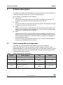
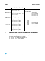
UM0833
User manual
Adjustable LED blinking speed
using STM8S-DISCOVERY touch sensing key
Application overview
The Discover software demonstrates the touch sensing feature of the STM8S-DISCOVERY
evaluation board. It may also be used as starter code for developers who need to manage
this touch sensing key within applications that require a user interface.
The STM8S-DISCOVERY is delivered with this code already programmed in the
STM8S105C6T6 microcontroller Flash memory.
Once the STM8S105C6T6 is powered-up through a USB cable connected to the host PC,
the LED LD1 starts blinking slowly, meaning that the programming has been completed
successfully.
■
Each time the TS1 key is pressed, LD1 blinking speed increases.
■
The third time TS1 is pressed, LD1 is switched off.
■
You can then restart a blinking cycle by pressing TS1 again.
The Discover demonstration software can available from the STM8S-DISCOVERY web
pages at http://www.st.com/mcu.
Reference documents
October 2009
■
STM8S-DISCOVERY evaluation board use manual (UM0817).
■
Developing and debugging your STM8S-DISCOVERY application code user manual
(UM0834).
Doc ID 16489 Rev 1
1/11
www.st.com
Contents
UM0833
Contents
1
2
3
2/11
Application description . . . . . . . . . . . . . . . . . . . . . . . . . . . . . . . . . . . . . . 4
1.1
Hardware required . . . . . . . . . . . . . . . . . . . . . . . . . . . . . . . . . . . . . . . . . . . 4
1.2
Application schematics . . . . . . . . . . . . . . . . . . . . . . . . . . . . . . . . . . . . . . . . 4
1.3
Application principle . . . . . . . . . . . . . . . . . . . . . . . . . . . . . . . . . . . . . . . . . . 5
Software description . . . . . . . . . . . . . . . . . . . . . . . . . . . . . . . . . . . . . . . . . 6
2.1
Touch sensing library configuration . . . . . . . . . . . . . . . . . . . . . . . . . . . . . . 6
2.2
Standard STM8S standard firmware library configuration . . . . . . . . . . . . . 7
2.3
Application software flowcharts . . . . . . . . . . . . . . . . . . . . . . . . . . . . . . . . . 8
2.3.1
Main loop flowchart . . . . . . . . . . . . . . . . . . . . . . . . . . . . . . . . . . . . . . . . . 8
2.3.2
ExtraCode_StateMachine flowchart . . . . . . . . . . . . . . . . . . . . . . . . . . . . 9
Revision history . . . . . . . . . . . . . . . . . . . . . . . . . . . . . . . . . . . . . . . . . . . 10
Doc ID 16489 Rev 1
UM0833
List of figures
List of figures
Figure 1.
Figure 2.
Figure 3.
Application schematics . . . . . . . . . . . . . . . . . . . . . . . . . . . . . . . . . . . . . . . . . . . . . . . . . . . . . 4
Main application loop flowchart. . . . . . . . . . . . . . . . . . . . . . . . . . . . . . . . . . . . . . . . . . . . . . . 8
ExtraCode_StateMachine flowchart . . . . . . . . . . . . . . . . . . . . . . . . . . . . . . . . . . . . . . . . . . . 9
Doc ID 16489 Rev 1
3/11
Application description
UM0833
1
Application description
1.1
Hardware required
The following STM8S-DISCOVERY on-board resources are used:
●
LED, LD1
●
Touch sensing key, TS1
No additional hardware is required to make this application software run on the STM8SDISCOVERY kit.
1.2
Application schematics
Figure 1 shows the touch sensing key implementation principle based on the RC acquisition
method. For STM8S-DISCOVERY implementation details, refer to the board schematic
provided in the STM8S-DISCOVERY user manual (UM0817).
Resistor R4 is the main resistor used to adjust the electrode touch sensitivity. Resistor R6
(10 KΩ) is optional. It is used to reduce noise sensitivity.
As soon as a finger touches electrode TS1, the STM8S microcontroller detects the small
variation in the RC network capacitance (composed of R4, R6 and electrode capacitance
CX). This is done by monitoring CX charge/discharge through PC1 (acquisition I/O).
For detailed information about RC acquisition principle for Touch Sensing applications, refer
to AN2927.
Figure 1.
Application schematics
6$$
,$GREEN
#4^P&
0#
LOAD)/
2-Ω
2Ω
%ARTH
2+Ω
0$
34-3
0#
ACQ)/
4 3
#8
AI
4/11
Doc ID 16489 Rev 1
UM0833
1.3
Application description
Application principle
This application uses the timer TIM4 as a time-base generator to control the blinking speed
of the LED LD1. Each time the STM8S microcontroller detects a touch event on TS1, TIM4
time base is reprogrammed to change the blinking speed.
At application start-up, the timer time base is configured to 1 second and LD1 toggles slowly
(every second). This configuration allows to check visually that the STM8S Flash memory
was successfully programmed.
Each time a touch event is detected on the TS1 key, LD1 blinking speed is increased
according to the timer time-base settings described in Table 1. At the third touch, the LED is
switched off. You can then restart the blinking cycle.
A
Table 1.
LED LD1 configuration
TS1 state
LD1 state
Timer time base
At start-up
LD1 toggles
1s
1st TS1 touch
LD1 toggles
200 ms
2nd TS1 touch
LD1 toggles
100 ms
3rd TS1 touch
LD1 is switched off
N/A
Doc ID 16489 Rev 1
5/11
Software description
2
UM0833
Software description
The application software uses both STM8 standard and touch sensing firmware libraries to
control general purpose functions, plus touch sensing peripherals.
These functions and peripherals are the following:
●
Clock (CLK)
The clock control enables and delivers the correct clock frequency to the CPU and
peripherals. It configures the HSI prescaler division factor from 8 to 1.
●
GPIOs
They drive the MCU I/Os to interface with external hardware. They configure port PD0
as output push-pull low to drive the LED LD1.
●
TIM3
TIM3 is a 16-bit timer with an 8-bit prescaler. The touch sensing firmware library uses
TIM3 for touch sensing acquisition (TIMACQ). See Table 2 for the corresponding define
statement in the STM8S touch sensing library.
●
TIM4
TIM4 is a basic 8-bit timer used as a generic time base (TIMTICK). This time base is
used by the touch sensing firmware library to control the charge/discharge cycles of the
RC network (resistor R4 plus TS1 electrode). TIM4 is also used by the application to
control LD1 blinking speed.
It is distinct from the acquisition timer TIM3. See Table 2 for the corresponding define
statement in the STM8S touch sensing library.
2.1
Touch sensing library configuration
The STM8_TSL_RC_Configuration.h file configures the touch sensing library.
Table 2 describes the main define statements required to configure the library for the
STM8S-DISCOVERY to control TS1 touch sensing key. The other define statements should
keep their default values. Refer to the STM8S touch sensing library online help for details
concerning these define statements.
Table 2.
Touch Sensing library configuration
Function
MCU selection
#define statement
Value
Comment
1
-
TIM3
0x5328
TIM3 base address
TIM4
-
GPIOC_BaseAdress
0x04
Port PC4 selected
STM8S
TIMACQ
Acquisition timer
TIMACQ_CNTR_ADD
Time-base timer
TIMTICK
LOADREF_PORT_ADDR
Load I/O
LOADREF_BIT
6/11
Doc ID 16489 Rev 1
UM0833
Table 2.
Software description
Touch Sensing library configuration (continued)
Function
#define statement
Value
SCKEY_P1_KEY_COUNT
SCKEY_P1_PORT_ADDR
SCKEY_P1_A
Single channel key
SCKEY_P1_DRIVEN_SHIELD_MASK
SCKEY_P2_COUNT
1
GPIOC_BaseAddress
0x02
0x08
0
0
SCKEY_P3_COUNT
Multichannel key
Comment
Number of keys = 1
Port PC selected
Pin 1 selected as
acquisition input
Pin 3 for active shield
Key port P2 not used
Key port P3 not used
0
Multichannel key feature
disabled
0x00
0x00
0x0A
0x00
0x00
0x00
0x00
0x00
0x00
Defines the electrode
mask for each GPIO
used.
Mask must be set to 0x00
for unused GPIOs.
NUMBER_OF_MULTI_CHANNEL_KEYS
GPIOA_ELECTRODES_MASK
GPIOB_ELECTRODES_MASK
GPIOC_ELECTRODES_MASK
GPIOD_ELECTRODES_MASK
Electrode mask
GPIOE_ELECTRODES_MASK
GPIOF_ELECTRODES_MASK
GPIOG_ELECTRODES_MASK
GPIOH_ELECTRODES_MASK
GPIOI_ELECTRODES_MASK
2.2
Standard STM8S standard firmware library configuration
The stm8s_conf.h file of the STM8S standard firmware library is used to configure the
library by enabling the peripheral functions used by the application.
The following define statements must be present:
●
#define _CLK 1 enables the clock control CLK
●
#define _GPIO 1 enables the GPIOs
Doc ID 16489 Rev 1
7/11
Software description
2.3
UM0833
Application software flowcharts
This section gives an overview of the application software main loop as well as of the
function that controls LD1 blinking speed.
Detailed information can be found in the STM8S-DISCOVERY software user manual
(UM0834).
2.3.1
Main loop flowchart
Figure 2 shows the flowchart of the application software main loop. Functions TSL_Init()
and TSL_Action() in the API of the touch sensing library initialize the library and control
the state machine that sequences the touch sensing management.
Figure 2.
Main application loop flowchart
3TART
#LOCK?#ONFIGURATION
#ONFIGURES(3%ASSYSTEMCLOCKSOURCE
&MASTER-(Z
'0)/?#ONFIGURATION
$POGJHVSFTQPSU1%BTPVUQVUQVTIQVMMMPX
UPESJWF-&%-%
-%JTTXJUDIFE
43,?)NIT
)NITIALIZESMEMORY!0)ANDSTRUC
INTHE4OUCHSENSING,IBRARY
%XTRA#ODE?)NIT
)NITIALIZES43KEYSTATEMACHINE
4UBSU5JNFS
4UBSUTUJNFS5*.DPOGJHVSFEBTUJNFCBTFGPS
-&%UPHHMJOHTQFFE
%XTRA#ODE?3TATE-ACHINE
)NCREMENTSVARIABLE"LINK3PEED MODULO
EACHTIMEATOUCHEVENTOCCURSON43
!CCORDINGTOTHEVALUEOF"LINK3PEED
MAKESTHE,%$BLINKATDIFFERENTRATESOR
SWITCHESITOFF
43,?!CTION
-AIN4OUCHSENSINGSTATEMACHINE
PERFORMINGTHESEQUENCINGOFALLTHEACTIONS
CONCERNINGTHETOUCHKEY
%ND
AI
8/11
Doc ID 16489 Rev 1
UM0833
2.3.2
Software description
ExtraCode_StateMachine flowchart
Figure 3 shows the detailed flowchart of the ExtraCode_StateMachine() function.
The ExtraCode_StateMachine() function implements the algorithm that controls the
LED blinking speed according to the number of times TS1 key is pressed.
LD1 blinking speed is controlled by the TIMTICK timer TIM4. This timer that is mainly used
by the touch sensing firmware library to control the charge/discharge timing of the RC
network, is already configured to generate a 100 ms time base. An interrupt is asserted
every 100 ms. It sets a dedicated User_flag_100ms flag to warn the application when the
counter has reached the preprogrammed value. The function Delay counts the number of
times this flag has been set before making the LED toggle. As a result, the delay time can
only be a multiple of 100 ms.
When a touch event is detected on TS1, the BlinkSpeed variable is incremented (modulo 3)
by the main routine (see Figure 3) and the delay time is modified resulting in a change of the
LED blinking frequency (refer to Table 1).
Figure 3.
ExtraCode_StateMachine flowchart
3TART
$ELAYS
4OGGLE,$
NO
#MJOL4QFFE
43TOUCHED
#MJOL4QFFE
YES
$ELAYMS
4OGGLE,$
NO
43TOUCHED
#MJOL4QFFE
YES
$ELAYMS
4OGGLE,$
NO
43TOUCHED
#MJOL4QFFE
YES
7RITE0$TO@
3WITCHOFF,$
YES
43TOUCHED
NO
AI
Doc ID 16489 Rev 1
9/11
Revision history
3
UM0833
Revision history
Table 3.
10/11
Document revision history
Date
Revision
29-Oct-2009
1
Changes
Intitial release.
Doc ID 16489 Rev 1
UM0833
Please Read Carefully:
Information in this document is provided solely in connection with ST products. STMicroelectronics NV and its subsidiaries (“ST”) reserve the
right to make changes, corrections, modifications or improvements, to this document, and the products and services described herein at any
time, without notice.
All ST products are sold pursuant to ST’s terms and conditions of sale.
Purchasers are solely responsible for the choice, selection and use of the ST products and services described herein, and ST assumes no
liability whatsoever relating to the choice, selection or use of the ST products and services described herein.
No license, express or implied, by estoppel or otherwise, to any intellectual property rights is granted under this document. If any part of this
document refers to any third party products or services it shall not be deemed a license grant by ST for the use of such third party products
or services, or any intellectual property contained therein or considered as a warranty covering the use in any manner whatsoever of such
third party products or services or any intellectual property contained therein.
UNLESS OTHERWISE SET FORTH IN ST’S TERMS AND CONDITIONS OF SALE ST DISCLAIMS ANY EXPRESS OR IMPLIED
WARRANTY WITH RESPECT TO THE USE AND/OR SALE OF ST PRODUCTS INCLUDING WITHOUT LIMITATION IMPLIED
WARRANTIES OF MERCHANTABILITY, FITNESS FOR A PARTICULAR PURPOSE (AND THEIR EQUIVALENTS UNDER THE LAWS
OF ANY JURISDICTION), OR INFRINGEMENT OF ANY PATENT, COPYRIGHT OR OTHER INTELLECTUAL PROPERTY RIGHT.
UNLESS EXPRESSLY APPROVED IN WRITING BY AN AUTHORIZED ST REPRESENTATIVE, ST PRODUCTS ARE NOT
RECOMMENDED, AUTHORIZED OR WARRANTED FOR USE IN MILITARY, AIR CRAFT, SPACE, LIFE SAVING, OR LIFE SUSTAINING
APPLICATIONS, NOR IN PRODUCTS OR SYSTEMS WHERE FAILURE OR MALFUNCTION MAY RESULT IN PERSONAL INJURY,
DEATH, OR SEVERE PROPERTY OR ENVIRONMENTAL DAMAGE. ST PRODUCTS WHICH ARE NOT SPECIFIED AS "AUTOMOTIVE
GRADE" MAY ONLY BE USED IN AUTOMOTIVE APPLICATIONS AT USER’S OWN RISK.
Resale of ST products with provisions different from the statements and/or technical features set forth in this document shall immediately void
any warranty granted by ST for the ST product or service described herein and shall not create or extend in any manner whatsoever, any
liability of ST.
ST and the ST logo are trademarks or registered trademarks of ST in various countries.
Information in this document supersedes and replaces all information previously supplied.
The ST logo is a registered trademark of STMicroelectronics. All other names are the property of their respective owners.
© 2009 STMicroelectronics - All rights reserved
STMicroelectronics group of companies
Australia - Belgium - Brazil - Canada - China - Czech Republic - Finland - France - Germany - Hong Kong - India - Israel - Italy - Japan Malaysia - Malta - Morocco - Philippines - Singapore - Spain - Sweden - Switzerland - United Kingdom - United States of America
www.st.com
Doc ID 16489 Rev 1
11/11