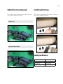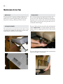
1
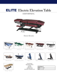
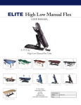
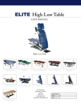
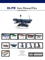
ELITE Auto Manual Flex
user manual
Auto Manual Flexion Table
Child Stationary
Stationary
Pump Control Elevation
Electric Elevation
Manual Flex
Automatic Flex
Automatic Manual Flex
High Low
High Low & Elevation
High Low Flex
22 John Street
Hagersville, Ontario
Canada
NOA-1H0
1-800-689-4730
www.elite-chirotables.com
Therapy / Massage
Serial Number
Model
Date
AUTO-MAN-FLEX
ELITE Manufacturing, ©2009, All rights Reserved
22 John Street ¤ Hagersville, ON NOA-1HO ¤ 1 800 689•4730, fax 905 768•0822 ¤ www.elite-chirotables.com
Table of contents | iii
Contents
1
Safety Instructions
1
Important Notice. . . . . . . . . . . . . . . . . . . . . . . . . . . . . . . 1
Electrical Safety Instructions . . . . . . . . . . . . . . . . . . . . . . . . . . 1
2
Drops & Cushions
2
Drops. . . . . . . . . . . . . . . . . . . . . . . . . . . . . . . . . . . . 2
Elevate Cushion & Ankle Rest . . . . . . . . . . . . . . . . . . . . . . . . . 2
3
Headpiece
3
Standard Headpiece . . . . . . . . . . . . . . . . . . . . . . . . . . . . . 3
Headpiece - Adjusting the Position. . . . . . . . . . . . . . . . . . . . . . . 4
Headpiece Optional Dual Drop - How to use the Toggle Drop . . . . . . . . . . . 5
Headpiece Optional Dual Drop - How to use the Forward Motion Drop. . . . . . . 7
HP-Flex Headpiece. . . . . . . . . . . . . . . . . . . . . . . . . . . . . . 9
HP-Flex-L Headpiece . . . . . . . . . . . . . . . . . . . . . . . . . . . . . 10
Installing the Paper Roller. . . . . . . . . . . . . . . . . . . . . . . . . . 10
4
Thoracic Breakaway
11
Thoracic Breakaway - How to release the breakaway . . . . . . . . . . . . . . 11
Thoracic Breakaway - How to use the drop . . . . . . . . . . . . . . . . . . . 13
5
Automatic Manual Flexion Table
15
Table Overview. . . . . . . . . . . . . . . . . . . . . . . . . . . . . . . 17
Convert to Manual Flexion - Overview . . . . . . . . . . . . . . . . . . . . . 18
Convert to Automatic Flexion - Overview . . . . . . . . . . . . . . . . . . . . 18
Convert to Automatic Flexion - Step By Step. . . . . . . . . . . . . . . . . . 19
Convert to Manual Flexion - Step By Step. . . . . . . . . . . . . . . . . . . . 20
Manual Flexion Function - Step By Step. . . . . . . . . . . . . . . . . . . . 21
Table Elevation (optional) . . . . . . . . . . . . . . . . . . . . . . . . . . 22
Table Lateral Flex. . . . . . . . . . . . . . . . . . . . . . . . . . . . . . 22
Table Distraction (optional) . . . . . . . . . . . . . . . . . . . . . . . . . . 23
Installing Flex Straps . . . . . . . . . . . . . . . . . . . . . . . . . . . . . 23
Table Specifications . . . . . . . . . . . . . . . . . . . . . . . . . . . . . 23
iv | Table of contents
Contents
6
Table Maintenance & Support
24
Part List . . . . . . . . . . . . . . . . . . . . . . . . . . . . . . . . . . 24
All Models. . . . . . . . . . . . . . . . . . . . . . . . . . . . . . . . . 24
Automatic Flexion Model Only. . . . . . . . . . . . . . . . . . . . . . . . 24
Maintenance & Care Tips . . . . . . . . . . . . . . . . . . . . . . . . . . . 25
Control Box Fuse Replacement. . . . . . . . . . . . . . . . . . . . . . . . 26
7
Warranty
27
Return Policy. . . . . . . . . . . . . . . . . . . . . . . . . . . . . . . . 27
|
1
1
Safety Instructions
Please study the Safety Instructions and all Operating Instructions in this manual before operating your new ELITE
table. Failure to follow these instructions may result in injury
to you or your patient.
Important Notice
Doctors and patients must keep hands, fingers and feet clear
and away when the table is raised or lowered. Injury could
ensue.
Patients hands should be kept on the Arm Rest.
Do not allow patients to get on or off table when table is
raising or lowering
Patients should get on or off table when table is at it’s lowest
position, and all motion ceased.
Never leave table unattended, or in operation with patients or
children present
Electrical Safety Instructions
If your table is equipped with an electric motor, connect the
table only to an outlet which is grounded and connected to a
properly fused or breaker-controlled circuit.
Make certain all electrical cords are in good condition.
Power cords have to be away from all pinch points or moving
parts, especially EA Electric Elevation Table, High Low, and
High Low Elevation Table and Flex table.
2
| 2
Drops & Cushions
For controls on the main portion of the table, headpiece
excluded.
Drops
Elevate Cushion & Ankle Rest
Drop tension is adjusted by turning the drop tension adjust
knob. Turn clockwise to tighten or counter-clockwise to
loosen.
Elevation of the cushion or ankle rest sections is achieved by
placing fingers beneath cushion frame and lifting to desired
angle. To return cushion or ankle rest to normal horizontal
position, pull up on the cushion elevation release lever.
Tension adjustments are very sensitive.
Recommended: Half turn and test for desired drop pressure.
|
3
Headpiece
Elite tables can be ordered with a variety of different headrests.
Standard Headpiece
Our standard multidirectional headpiece includes tilt, elevation and spread. The headpiece also contains a cervical drop
either forward motion oriented or straight down motion.
Paper Cutter
Use the Paper Cutter to cleanly tear/cut the headrest
paper.
Tilt Release Knob
To raise the headpiece to the desired angle pull up on the
headpiece bracket until desired tilt is reached. To lower
the headpiece tilt press the Tilt release knob and move
headpiece to desired angle.
Cushion Spread Adjust Knob
Lift knob slightly and move forward or backward to
achieve desired cushion spread.
Cervical Drop Tension Adjust
Turn knob clockwise to tighten drop tension, counterclockwise to decrease tension.
Cervical Drop Cocking Lever
Push down lever to cock the drop.
Elevation Release Lever
To lower rear headpiece cushion, pull up and release. To
raise rear side of headpiece, place hands under both sides
of the face cushion base and raise to desired height
3
4
| Headpiece - Adjusting the Position
The following illustrates the various position adjustments for the standard headpiece.
1. Neutral Position
2. Push knob in
3. Tilt down
4. Headpiece tilted down
5. Grasp bar and tilt up
6. Headpiece tilted up
7. Raise back side of headrest
8. Headrest back side raised
9. Raise front of headrest
10. Headrest elevated
11. Lower rear of headrest
12. Headrest rear lowered
13. Lower front of headrest
14. Release knob
15. Headrest back in neutral position
|
5
Headpiece Optional Dual Drop - How to use the Toggle Drop
Our optional dual drop headpiece has both forward motion oriented and straight down motion.
The following illustrates how to perform a toggle drop.
Toggle Drop (Straight) - Start
To perform a forward motion drop follow these steps.
Adjust the drop tension to desired setting. Turn knob
clockwise to increase drop tension and counter clock wise
to decrease tension.
Once the desired tension is set you will use the toggle drop
cocking lever.
Toggle Drop - Cocking Lever
Grasp the toggle drop cocking lever.
Toggle Drop -Cocking the Drop
Pull the lever towards you to cock the drop.
6
| Toggle Drop - Deploying the drop
Once the drop has been cocked push in a forward motion
and the drop will release.
Toggle Drop - Deployed Drop
Headpiece will drop to the un-cocked position.
|
7
Headpiece Optional Dual Drop - How to use the Forward Motion Drop
The following illustrates how to perform a forward motion drop.
Forward Motion Drop - Start
To perform a forward motion drop follow these steps.
Adjust the drop tension to desired setting. Turn knob
clockwise to increase drop tension and counter clock wise
to decrease tension.
Once the desired tension is set you will use the toggle drop
cocking lever.
Forward Motion Drop - Cocking Lever
Grasp the toggle drop cocking lever.
Forward Motion Drop -Cocking the Drop
Pull the lever towards you to cock the drop.
8
| Forward Motion Drop - Cocking Lever
Next Grasp the forward motion drop cocking lever.
Forward Motion Drop -Cocking the Drop
Push the lever forward to cock the drop.
Forward Motion Drop - Deploying the drop
Once the drop has been cocked push in a forward motion
and the drop will release.
Forward Motion Drop - Deployed Drop
Headpiece will drop to the un-cocked position.
|
9
HP-Flex Headpiece
Our new flexion/distraction headpiece includes all the
features of our standard multidirectional headpiece including flexion motions (long axis traction and flexion). In the
illustrations to follow the flex handle has been removed to
simplify the diagrams. In practice to use the flexion features
the flex handle must be inserted into the flexion headpiece.
Furthermore the flex headpiece straps must also be utilized.
Please view the standard headpiece instructions for operations of standard features.
Long Axis Traction
Flexion
With the patient on the table insert the flexion handle and
secure the flexion straps. Then following proper procedures
use the flexion handle to perform long axis traction.
With the patient on the table insert the flexion handle and
secure the flexion straps. Then following proper procedures
use the flexion handle to perform flexion.
Elevation
The headpiece can be elevated and lowered.
10 | HP-Flex-L Headpiece
Installing the Paper Roller
Our flexion/distraction and long axis traction headpiece
includes all the features of our standard multidirectional
headpiece and the HP-Flex headpiece and also includes
lateral flexion.
The following illustrates how to install the paper roller on the
headrest.
Please view the standard headpiece instructions and HP-Flex
instruction for operation details.
Lateral Flexion
With the patient on the table insert the flexion handle and
secure the flexion straps. Then following proper procedures
use the flexion handle to perform lateral flexion.
|
4
11
Thoracic Breakaway
Elite tables can be ordered with an optional breakaway thoracic section. The Illustration shows a breakaway with optional
drop in breakaway.
Thoracic Breakaway - How to release the breakaway
The following illustrates how to use the thoracic breakaway.
Breakaway - release knob
The tension for the breakaway can be adjusted by rotating the tension adjustment knob clockwise to increase, or
counter clockwise to reduce the amount of tension.
The breakaway release knob is shown here in the locked
position.
Breakaway - releasing the breakaway
Push the breakaway release knob towards the front of the
table to release the breakaway
12 | Breakaway -Released
Once the release knob has been pushed forward the breakaway will be released.
Breakaway - Testing the breakaway
Shown here the breakaway in action.
|
13
Thoracic Breakaway - How to use the drop
The following illustrates how to use the optional drop in the thoracic breakaway.
Breakaway - Lock the Breakaway
Push the breakaway release knob towards the back of the
table to lock the breakaway. Once locked the cushion will
not breakaway and will be ready to perform drops.
Breakaway - Drop Cocking Handle
To perform a drop follow these steps.
Adjust the drop tension to desired setting. Turn knob
clockwise to increase drop tension and counter clock wise
to decrease tension.
Breakaway - Cocking the Drop
Locate the drop cocking handle and push down to cock
the drop.
14 | Breakaway - Drop Cocked
Shown here is the drop in the cocked position
Breakaway - Deploying the drop
Once the drop has been cocked push in a downward motion and the drop will release.
Breakaway - Deployed Drop
The thoracic cushion will drop to the un-cocked position.
| 15
5
Automatic Manual Flexion Table
Control Box
The Automatic & Manual Flex table has a digital control box that is used to operate the tables Automatic flexion features.
There are two modes of operation. Timed flexion where the flexion action will run for a period of time, or manual operation
where the chiropractor controls the length of the operation. The control box also has a dial for selecting the flexion speed of
the table.
Flexion Speed Dial
On / Off Switch
Use to adjust the flexion
speed.
Starts and stops the table
flexion motion
Timer or Manual Toggle
Use to select either timed
operation or manual operation mode.
Mode (sec, min, hrs)
Use to set your timed flexion
to be in second, minutes or
hours.
Flexion Duration Display
The duration is read first by
looking at the select units and
then the time. Show here
is a selection duration of 3
minutes and 19 seconds.
Timed Operation - Automatic Flexion:
Set Timed Flexion Duration
Use to increase or decrease
the timed duration of the
flexion operation.
Manual Operation - Automatic Flexion
1. Switch the ‘Timer or Manual’ toggle to ‘Timer’
1. Switch the ‘Timer or Manual’ toggle to ‘Manual’
2. Switch the ‘On & Off Switch’ to ‘On’
2. Adjust the flexion speed of the table by turning the
‘Speed Dial’ .
3. Select ‘Mode’ to the desired units of time, either seconds, minutes or hours. Most common usage would be
minutes.
4. Set the amount of time using the ‘Increase & Decrease’
buttons. Remember that the time displayed on the digital display is in the units specified by the lights beside the
mode button (seconds, minutes or hours).
5. Adjust the flexion speed of the table by turning the
‘Speed Dial’ .
6. Push the Start button to begin flexion, and the Stop button to end the Flexion.
3. Switch the ‘On & Off Switch’ to ‘On’ and the Flexion
action will begin.
4. To stop the Flexion action switch the ‘On & Off Switch’
to ‘Off ’
16 | Safe Operation
The speed control dial of the “ELITE FLEXION CONTROL” is not considered a safe way to isolate the movement of the
table. Anytime a patient is entering or existing from the table, power to the drive motor must be removed. This is done by
placing the controller’s “ON/OFF” switch into the “OFF” position. If this switch should become damaged or faulty, over the
expected life span of the unit, the controller must be removed from service.
Setting the speed control dial to zero to inhibit bed movement while not in use may cause early component failure and presents a safety hazard. The controller’s “ON/OFF” switch must be placed into the “OFF” position anytime the bed movement
function is not required.
If you perform any mechanical adjustments to the drive motor link assembly or any electrical service to motor or drive
controller, ALL POWER MUST BE REMOVED TO THE CONTROLLER. This can be done by unplugging the drive
controller from its power source and allowing a few minutes for the controller to discharge any stored power before performing any service work.
Safe Operation Explained:
The “ELITE FLEXION CONTROL” is a high quality, simple to use, motor speed regulator best suited where applications
do not require an exact speed set point. These controllers have a +/- 5% error factored into their speed regulation. This error
can be magnified at the consumer’s location as voltage fluctuates from area to area. At the high end, this will cause the drive
motor to either not reach maximum RPM speed or go slightly above it, all within the motor’soperational specs. The same
could be found at the low end of the motor’s RPM range. This is within normal functionality for this application.
| 17
Table Overview
Headpiece
Control Box
Cushion Release
Flexion Handle
Knee Break
Standard multi-directional headpiece
Controls flexion
operation.
Pull up on lever to
return cushion to
horizontal position.
Use for manual flexion operation.
Adjusts up 20
degrees, down
10 degrees with
Drop Tension Control
Rotate clockwise for
more tension, counter
clockwise to reduce
tension.
Flexion Handle Release Knob
pull knob to insert or remove
the flexion handle
Armrest
Patient armrest.
Tension Crank
Distraction Foot Pedal
Turn clockwise to
increase tension,
counter clockwise
to reduce.
Drop Cocking Levers
Push down lever with
foot to cock the drop(s).
Used to distract the
rear section of the table.
(optional feature)
Elevation Foot Pedal
Use the foot pedal to
raise and lower the table
top. (optonal feature)
Lateral Flexion Lock
Automatic / Manual Conversion Knob
Tighten lever to lock rear of
table in current position. Can
be locked in the horizontal
position or during manual
flexion used to lock current
flexe position
For automatic flexion operation this
knob must be screwed in as shown in
diagram.
For manaul flexion operation this
knob must be un-screwed and the arm
stowed under the tale.
18 | Convert to Manual Flexion - Overview
Convert to Automatic Flexion Overview
To convert from Automatic Flexion operation to Manual
Flexion operation follow these steps.
To convert from Manual Flexion operation to Automatic
Flexion operation follow these steps.
Automatic to Manual Conversion
1. Make sure the Control Box on/off switch is switched in
the off position and the table is unplugged.
2. Unscrew the ‘Automatic / Manual Conversion knob’ and
stow the handle under the table as shown in the diagram
below.
3. Insert the Flexion Handle
Manual to Automatic Conversion
1. Grasp the ‘Automatic / Manual Conversion bar’ stow
under the table and attach it to the motor flexion bracket
as shown in the diagram above
2. Remove the flexion handle
3. Set the control box to either manual or timed flexion
operation and start the flexion motion.
| 19
Convert to Automatic Flexion - Step By Step
To convert from Manual Flexion operation to Automatic Flexion operation follow these steps.
Step #1
Step #4
Remove the
flexion bar from
the clip under the
table.
Now that you
have the knob
secure the flexion
bar to the motor
bracket with the
knob by turning
clockwise.
Step #2
Step #5
Move the arm to
the flexion motor attachment
bracket.
Turn the knob
clockwise until
the knob secured
tight.
Step #3
Step #6
Remove the knob
from the storage location by
turning counter
clockwise.
The table is now
ready for automatic flexion
operation.
20 | Convert to Manual Flexion - Step By Step
To convert from Automatic Flexion operation to Manual Flexion operation follow these steps.
Step #1
Step #4
Unscrew the ‘Automatic / Manual
Conversion knob’
from the flexion
motor bracket.
The knob shown
here has been set
in the storage location by turning
clockwise.
Step #2
Step #5
Turn the knob
counter clockwise
until you can
remove the knob.
Then store the
knob as shown in
step #2.
Store the automatic flexion bar
underneath the
table. There is a
holder that the
bar will clip into
Step #3
Step #6
Store the knob
you have just
unscrewed on the
storage location
on the side of the
table
Once the flexion
bar has been
clipped in the
storage location
then the table is
ready for manual
flexion.
| 21
Manual Flexion Function - Step By Step
The following illustrates the steps used to perform manual flexion. The flexion tension can be set at the rear of the table by a
crank or if your table as the optional electric tension adjustment then you can use a foot pedal to adjust the tension.
1. Table in locked position
2. Loosen flex lock
3. Flex down
4. Grasp the lateral flex lock
5. Loosen lateral flex lock
6. Table un-locked
7. Able to perform figure 8 (ROM)
8. Flexed down and left
9. Flexed down and right
10. Grasp flex lock
11. Tighten flex lock
12. Grasp lateral flex lock
13. Tighten lateral flex lock
14. Pull flexion bar release knob
15. Remove flexion handle
22 | Table Elevation (optional)
Table Lateral Flex
If your table is equipped with the table elevation feature then
you are able to control the height of the table with the tap of
a footswitch.
Your table is able to flex laterally at the front and back of the
table.
Table Lowered
Table Front & Back Flexed Right
Table Raised
Table Front & Back Flexed Left
| 23
Table Distraction (optional)
Installing Flex Straps
If your table is equipped with the electrical distraction then
you can distract the rear of the table.
Flex straps are clipped into the loops under the cushions as
shown in the following illustration.
Table Distracted
Table Not in Distracted Position
Table Specifications
Automatic Manual Flex
Weight
408 lbs / 185 kg
Weight Skidded
458 lbs / 207 kg
Weight Crated
608 lbs / 275 kg
24 | 6
Table Maintenance & Support
ELITE Chiropractic tables have been called “The Workhouse of the Industry” and while we stand behind the
superior function and low maintenance needs of each model,
replacement parts are available should they be required.
Part List
Minimum shipping orders apply to all parts ordered. For
further information please contact your ELITE Chiropractic
table dealer or ELITE Manufacturing, 1-800-689-4730.
All Models
1. Drop springs (1 for each drop)
2. Steel drop ball (2 for each drop)
3. Cervical drop tension rod with knob
4. Thoracic / Lumbar / pelvic tension rod with knob
5. Drop Tension control rod receptacle
6. Thoracic drop assembly
7. Lumbar drop assembly
8. Pelvic drop assembly
9. Headrest with cervical drop (complete)
10. Headrest paper cutter assembly
11. Headrest paper holder assembly
12. Headrest paper roller (wood)
13. Drop cocking foot pedal
14. Clevis pins (large)
15. Clevis pin (small)
16. Clevis cotter pins
17. Elevation Motor
18. Foot switch
Automatic Flexion Model Only
19. Flexion Handle
20. Flexion Motor
21. Digital Control Box
20 | Maintenance & Care Tips
Upholstery Care
To prolong the life of upholstery (Whisper, Burkshire &
leather) we recommend regularly wiping cushions with a
damp cloth containing a mild soap and water solution.
Locating the Serial Number
The serial number is located at the back of the table as shown
in the illustrations bellow. You will need this number when
making inquires to ELITE customer support.
Moving Your Table
We recommend having two people move the table. One
person at each end of the table. The following will illustrate
the proper location to lift the table. Please be aware that the
tables are heavy so only attempt moving the tables if you are
comfortable with the weight.
The person lifting from the front of the table should push the
headrest Tilt Release Knob in to lock the upward motion of the
headrest. When you apply upward force the headrest should
not move
The person lifting from the back of the table should lift holding onto the handles as shown bellow.
|
21
Control Box Fuse Replacement
If a your table has a motor that is not functioning properly
then the first step to performed is to replace the fuses in the
control box. Follow the steps outlined below.
Control Box Location
Unplug your table from the wall outlet and then locate
the Control Box by tilting the table as shown and laying it
down on it’s side. Then look for the grey box that has the
power cable running to it.
Opening the Fuse Compartment
Using needle nose pliers pull the fuse box plug out of the
Control Box.
*Note - You should leave the Control Box in the table (as
shown in the previous photo), the photo’s used here show a
control box that has been removed from the table for clarity of illustration.
Replacing the Fuses
You will find two spare fuses in the plug that you just
removed.
Replace the two fuses in the control box with the spares
from the plug. Once this is complete put the plug back
into the control box. Then stand the table upright again
and plug it back into the wall outlet. You can now try using your table again to see if it has resolved the problem.
NOTE: If you have already used the spares fuses previously then you will have to contact ELITE to order new fuses.
22 | 7
Warranty
All products (and parts thereof ), manufactured and sold by
Elite Manufacturing (1180396 Ontario, Inc.) are warranted
to be free from defects in material and workmanship for a
period of two years from the date of shipment.
If notice of claim is made within the warranty period, Elite
Manufacturing will repair or replace, at its option, the product or part which is defective.
The customer must obtain prior authorization from Elite
Manufacturing to return defective parts or to have repairs
performed by non-Elite personnel (exclusive of authorized
Elite dealers). Labour charges to remove or replace defective
parts are not covered by this warranty.
Defective conditions caused by misuse, abuse, acts of God,
accidents, abnormal use or stress, modifications or any other
matter unrelated to Elite Manufacturing and beyond its
reasonable control are not covered.
In no event shall Elite Manufacturing (or its agents) be liable
for loss of use, revenue, or profit or for indirect consequential
damages.
Upholstery materials and fabric are not warranted under
this agreement. We suggest prolong life of upholstery can
be obtained by regular wiping cushions with a damp cloth
containing a mild soap and water solution.
Return Policy
ELITE MANUFACTURING
Division of 1180396 Ontario Inc.
1. Any order placed with us but cancelled in writing
prior to shipping by us will be given a full credit
(refund).
2. Any goods that have been shipped or are in the
process of shipping by us will be subject to a 20%
restocking charge plus any shipping costs incurred
by us for shipment out and return of such goods.
3. On any returned goods, we reserve the right to
inspect same prior to credit (refund) and any damage
of defects or missing items from the goods will incur
charges in addition to the restocking charge and
freight charges.
4. If Elite has received payment from customer, Elite
will refund the difference to our customer after any
of the above charges.