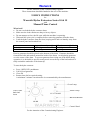
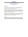
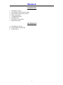
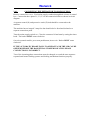
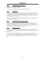
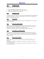
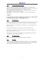
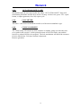
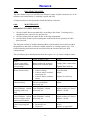
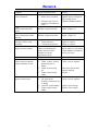
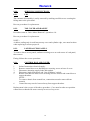
1
Warwick Dryers rapid dry The Operating Manual hydro extractor CE marking All dryers are tested and CE marked by Advantica Technologies Ltd. (previously known as British Gas.) Manual timer Controls the spin cycle time for up to six minutes. Coin mechanism The coin operated models come with a strong coin box housing, neatly mounted to the extractor. Lid safety switches A concealed safety device ensures the extractor does not operate until the lid is securely locked. MANUFACTURED IN THE UK Warwick Hydro Extractor Manual Series 10 with Manual Timer Control And Coin Token Operated Control 1 Warwick 2 Warwick For the Attention of the Commissioning Engineer. These instructions should be handed to the user of the machine. USER’S INSTRUCTIONS for Warwick Hydro Extractors Series 10 & 15 with Manual Timer Control What load? Do not overload the hydro extractor drum. Make sure the load contains no sharp or heavy objects. Do not attempt to force the lid open while the machine is operating. Wait until the spin cycle is complete before removing garments from the drum. Load the hydro extractor from the front, keeping water and wet laundry away from the control panel and terminal box. Approximate dry weight 8 – 10 kg 13 – 15 kg Series 10 Series 15 Effective wet weight limit 12.26 kg 18.39 kg Heavier garments should be placed at the bottom of the drum. Garments should be formed into balls and stacked around the inside of the drum. Avoid placing garments over the centre of the drum. To prevent garments from rising out of the drum during operation, it is advisable to spread a strong towel across the top of the load and tuck it tidily around the underside of the drum top. To start the hydro extractor Press ‘OPEN LID’ pushbutton. Lift lid, load garments. Close lid Rotate timer dial to required setting. A minimum 3-minute extraction time is recommended by the manufacturer. Green Lamp Timer, timer knob and insert Amber Lamp Black Pushbutton Control Panel For the Attention of the Commissioning Engineer. 3 Warwick These instructions should be handed to the user of the machine. USER’S INSTRUCTIONS for Warwick Hydro Extractors Series 10 & 15 with Coin/token Operated Control What load? Do not overload the hydro extractor drum. Make sure the load contains no sharp or heavy objects. Do not attempt to force the lid open while the machine is operating. Wait until the spin cycle is complete before removing garments from the drum. Load the hydro extractor from the front, keeping water and wet laundry away from the control panel and terminal box. Series 10 Series 15 Approximate dry weight 8 – 10 kg 13 – 15 kg Effective wet weight limit 12.26 kg 18.39 kg Heavier garments should be placed at the bottom of the drum. Garments should be formed into balls and stacked around the inside of the drum. Avoid placing garments over the centre of the drum. To prevent garments from rising out of the drum during operation, it is advisable to spread a strong towel across the top of the load and tuck it tidily around the underside of the drum top. To start the hydro extractor Press ‘OPEN LID’ pushbutton. Lift lid, load garments. Close lid Insert coin/token. Depress green ‘START’ pushbutton. Green Lamp Green Pushbutton Amber Lamp Red Pushbutton Black Pushbutton Control Panel 4 Warwick HYDRO EXTRACTOR EX10 USER’S MANUAL IMPORTANT :THE WARRANTY ON THIS HYDRO EXTRACTOR IS RENDERED VOID UNLESS IT IS INSTALLED AND USED IN ACCORDANCE WITH THE INSTRUCTIONS CONTAINED IN THIS MANUAL. THIS MANUAL HAS BEEN DESIGNED TO GUIDE YOU THOUGH ALL STAGES OF OWNERSHIP OF YOUR EXTRACTOR, RIGHT FROM THE POINT WHERE YOU ARE PLANNING YOUR INSTALLATION. PLEASE READ IT CAREFULLY, THIS WAY YOU WILL ENSURE THAT YOUR EXTRACTOR GIVES THE BEST POSSIBLE SERVICE. THE MANUAL ALSO CONTAINS IMPORTANT SAFETY INSTRUCTIONS, DESIGNED TO ENSURE THAT THE EXTRACTOR WILL BE SAFE WHEN PROPERLY INSTALLED, COMMISSIONED AND MAINTAINED. PLEASE FOLLOW THESE INSTRUCTIONS CAREFULLY. NOTE :IT IS ESSENTIAL THAT ELECTTRICAL INSTALLATION WORK IS CARRIED OUT BY AUTHORISED SPECIALISTS AND THAT CORRECT DIRECTION OF ROTATION OF THE DRIVE MOTOR IS ESTABLISHED. 5 Warwick CONTENTS 1. 2. 3. 4. 5. 6. 7. 8. INTRODUCTION PLANNING FOR ISTALLATION DELIVERY AND UNPACKING INSTALLATION COMMISSIONING OPERATION ROUTINE CLEANING MAINTENANCE APPENDICES A. TECHNICAL DATA B. EXPLODED DIAGRAMS C. PART LISTS 6 Warwick 1.0.0. INTRODUCTION This manual has been designed to guide you through all stages of ownership of your extractor. Right from the point where you are planning the installation. Please read it thoroughly, follow the instructions carefully, this way you will ensure that your extractor gives you the best possible service. The manual also contains important safety instructions, designed to ensure that the extractor will be safe when properly installed, commissioned and maintained. Please follow these instructions especially carefully. NOTE :It is essential that authorised specialists carry out electrical installation work. When ordering spare parts, please quote serial number of extractor, which is located on specification plate at rear of machine. 7 Warwick 2.0.0. PLANNING FOR INSTALLATION. IMPORTANT SAFETY POINTS : Ensure adequate lifting equipment is available for delivery. Allow sufficient access to machine for service engineer. Direct water drainage pipe carefully away from electrical connections. Use a competent electrician and pipework specialist. Ensure your service supplies are adequate. 2.1.0. STRENGTH OF FLOORS. The extractor must be sited on a levelled concrete floor. The weight of the ‘Warwick EX10’ hydro extractor is 100kg. The extractor must be bolted down securely, by means of three fixing bolts at positions shown in Figure 1. 2.2.0. SPACE FOR INSTALLING. Access for connecting up, commissioning and maintenance. From time to time it may be necessary to have service work carried out on the extractor. It is recommended therefore that 45cm (18”) of free space is left around the machine to allow easy access to electrical and drainage connection points. See figure 1 for General Dimensions. 2.3.0 WATER OUTLET. The drainage pipe from the extractor outlet should be run to a separate drain. If it is connected to a sealed drain with washing machine outlets, it is preferably that the drain has an air vent and is strongly recommended that a trap is installed between the drain and the extractor to prevent the likelihood of water and soap suds from any washing machines being drawn back into the extractor. 2.4.0. ELECTRICITY. The extractor is supplied ready wired and only requires connection to a proper supply. This work should be undertaken by an approved electrician. The supply should be wired in accordance with the current edition of the I.E.E regulations for the electrical installations. Each extractor should be provided with a separate isolator at the connection point and should be separately fused. The extractor requires a 3 phase, 420v, 50 Hz ac. (3 Phase, Neutral and Earth). Recommended cable size I.D. 1.5mm² installed in conduit or trunking. Check that the supply and meter are suitable for this current. Consult circuit diagram supplied with this manual. 8 Warwick 2.4.1. CONNECTING THE EXTRACTOR TO MAINS SUPPLY. Remove control box cover. Feed mains supply conduit through hole in base of control box. Connect the three phase L1, L2, L3 to the connection block as shown in circuit diagram. A separate neutral (N) and protective earth (E) lead should be connected to the machine. The machine has an integral 3-amp fuse but should also be fused and isolated at a separate connection point. Turn the mains supply switch on. Close the extractors lid and start by setting the timer knob. The basket MUST rotate clockwise. On coin operated models, press start push button, insert coin. Basket MUST rotate clockwise. IF THE AUTOMATIC BRAKE FAILS TO OPERATE AND THE LID CAN BE OPENED BEFORE THE BASKET HAS STOPPED ROTATING PHASE CONNECTION IS INCORRECT. Two of the incoming phase connections must be changed over and the start sequence repeated until motor braking systems and locking mechanism functions properly. 9 Warwick 3.0.0. DELIVERY AND UNPACKING. IMPORTANT SAFETY POINTS : Ensure you have adequate equipment to off-load the extractor. 3.1.0. DELIVERY. Extractors are delivered bolted onto pallets by means of there fixing points. They are covered with polythene and strong corrugated cardboard for protection. If a vehicle with tail lift is not available and a proper loading bay is not available, a fork lift of suitable capacity will be required. Great care should be taken to avoid damage off-loading, as no responsibility can be accepted by the manufacturers. 3.2.0. CHECKS BEFORE DE-PALLETISING The cardboard should be removed first. Despite precautions taken there is always a possibility of damage during transit and it is sensible to make a careful inspection. Although it is unlikely that any error will be made in supply or delivery, it is wise to check the extractor specification against your needs. 3.3.0. DE-PALLETISING First undo the bolts holding the extractor to the pallet. These are positioned at the end of each arm of the tri-form base chassis and are accessible through the three lower service panels. The bolts should be taken out of their holes to prevent any risk of damage. The extractor can now be ‘walked’ off the pallet, it is recommended that two people are available for this. It should be handled only by outer casing and not by the control box. 10 Warwick 4.0.0. INSTALLATION. IMPORTANT SAFETY POINTS : Call in a competent electrician. Provide proper isolation for incoming electrical supply. Install in accordance with regulations. 4.1.0. POSITIONING. When the extractor has been checked over and de-palletised, it can be walked into place by two people or skidded on smooth hardboard or a metal plate. The floor should be first cleared of any loose material. 4.2.0. LEVELLING. The extractor must be bolted down onto a level concrete floor using suitable anchor bolts. (See Figure 2) expansion bolts are not recommended. Check that the extractor is standing level and tighten the three fixing bolts securely. Failure to do this could cause excessive vibration during operation and may result in serious damage to the equipment. 4.3.0. ELECTRICAL CONNECTIONS. An approved electrician must be employed and installation should be in accordance with statutory regulations. Each extractor should be wired via, its own isolator and separate fuse, appropriate to the extractor’s requirements. 11 Warwick 5.0.0. COMMISIONING IMPORTANT SAFETY POINTS : Check the equipment carefully in the order given. Adjust ‘OUT OF BALANCE’ switch only as specified. Ensure lid lock switches operate properly. 5.1.0. COMMISIONING It is important for safety reasons to carry out the commissioning checks and operations in the correct sequence. This will ensure that the extractor is correctly adjusted and properly connected to all services. 5.2.0. LEVELLING Check that the extractor is level and does not rock. Re-tighten bolts if necessary and lock down securely. 5.3.0. LID LOCK MECHANISM Check that the electricity supply is switched off. Remove control box cover, using finger pressure only, pivot-locking lever to ensure smooth operation of locking mechanism. Undue force should not be required to release. The locking mechanism is factory set but should be adjusted if necessary. 5.4.0. ELECTRICAL CONNECTIONS Check that the electrical connections to the terminal box are as shown on circuit diagram in of box. Switch on power to the machine and check correct order of phase input. Incorrect phase input can allow extractor lid to be opened before basket has stopped spinning. 5.5.0. MOTOR SUSPENSION Check that the motor is securely bolted to support shaft and that locking screw is tightened. Check the three suspension clamping nuts are fastened down equally and that the extractor base is level. The suspension unit is factory set but may loosen after extended usage. See Figure 2 for correct adjustment. 12 Warwick 5.6.0. OUT OF BALANCE SWITCH. The ‘Out of Balance’ control is pre-set by the manufacturer. To check correct operation, a 2lb (0.9kg) weight should be laid in place to the inside of the inner basket. The motor should run without tripping the ‘Out of Balance’ switch. The weight shall then be increased to 2 ½ lb. (1.14kg) which must then operate the ‘Out of Balance’ control upon motor starting. Adjustment can easily be made to ‘Out of Balance’ switch position through lower service ports. WARNING IT IS ESSENTIAL THAT THE CORRECT FUNCTIONING OF THIS SWITCH IS CHECKED REGULARLY AS DESCRIBED ABOVE. 5.7.0. ADJUSTMENT. After a long period of operation, the rubber compression blocks may become worn and pressure plate adjustment may be necessary to achieve correct suspension stiffness. Tighten lock nuts (7) as required and ensure dimension ‘A’ is equal around pressure plate. (see fig. 2). If adjustment is insufficient, extractor basket will vibrate on motor start up. If pressure plate is tightened down too much, the basket will vibrate at high speed. Adjust until vibration ceases to occur. If adjustment is carried out the ‘Out of Balance’ switch setting must be checked for correct operation. (See sections 5.6 and 8.2.6). 5.8.0. WATER OUTLET. Check connection of flexible drainage hose to extractor water outlet. 5.9.0. PRE-RUN. The hydro extractor should now be run through a complete test cycle to check that all control, switching and locking functions are operating correctly. A demonstration of loading and operational procedure can now be given to the customer. 13 Warwick 6.0.0. OPERATION. IMPORTANT SAFETY POINTS : Do not overload extractor basket. Make sure load contains no sharp or heavy objects. Do not attempt to force lid when extractor motor is operating. Wait until cycle is complete before removing garments. Load machine from the front, keeping water and wet laundry away from control panel and terminal box. 6.1.0. WHAT LOAD? Do not overload the extractor. The effective weight limit for wet washing is :12.26kg This gives a dry weight of approximately 8-10kg. A minimum 3 minute extraction time for any load is recommended by the manufacturer. It is suggested that heavier garments be placed at the bottom of the basket. Avoid placing garments directly over the centre spinner. If a full load is to be put into the extractor, it is advisable to spread a strong towel across the top of the load and tuck it tidily around the underside of the basket top. ‘This will prevent any garments rising out from the basket during operation. 6.2.0. CONTROLS AND STARTING. 6.2.1. OPEN – LID BUTTON. The extractor lid can only be opened when current from the mains supply is switched on. Switch on mains supply. Press ‘Open – Lid’ button. Lift lid, load garments. Close lid securely. 6.2.2. TIMER. The timer is variable between 1 and 6 minutes. Select timer knob to desired setting. The drive motor will run. 6.2.3. ‘RUN’ LAMP. When the timer has been activated, the white / clear lamp will illuminate to indicate ‘RUN’ mode has been initiated. This lamp will remain on during ‘RUN’ cycle. 14 Warwick 6.2.4. ‘OUT OF BALANCE’ LAMP. Should the basket be unevenly loaded, the amber ‘OUT OF BALANCE’ lamp will immediately illuminate and the drive motor will stop. In this event, press ‘Lid – Open’ button, re-adjust garments, close lid, repeat cycle. 6.3.0. COIN METER. The timer / coin meter on laundrette models is of the non-accumulative type. 6.4.0. CYCLE COMPLETE. The ‘RUN’ lamp will remain on while extractor is running, going out when the time set or paid for has expired. At this point the motor will reverse brake, stop and the lock-lever solenoid will de de-energised. The lock mechanism will allow the extractor lid to be lifted when ‘Lid-Open’ button is depressed. Remove garments. 15 Warwick 7.0.0. ROUTINE CLEANING. The inner basket, top cover and lid of the Warwick range of hydro extractors are of all stainless steel construction, so cleaning is quick and easy. A frequent check for foreign bodies inside the basket is advised. 8.0.0. MAINTENANCE IMPORTANT SAFETY POINTS : Always trouble shoot systematically, according to the charts. If testing on live equipment, have someone else present also. Always isolate from the mains before removing components. Always check features before putting the extractor back into operation if it has been serviced. The first part consists of trouble-shooting charts, which enable you to find out where the problem is and often to effective simple remedies (re-setting controls, etc). The trouble-shooting chart must not be used until after the extractor has been fully commissioned. The second part gives detailed instructions for repairs, etc. of a more complex nature. Problem 8.1.1. Lid can open while basket rotating brake not operating. 8.1.2. Motor does not start. 8.1.3. Lid not closing. 8.1.4. ‘Out of Balance’ switch operating with even load. 8.1.5 ‘Out of Balance’ switch does not operate when load is out of balance. 8.1.6. Timer not giving full time. Check Possible Cause Action Phase connection incorrect. Drum loose on motor shaft. Change phase connections. Tighten drum lock nut. 1. Lid not closing. 2. Lid lock micro-switches incorrectly set. 3. Lid lock micro-switches faulty. Press down lid. Adjust. Lid lock mechanism incorrectly set. Adjust. ‘Out of Balance’ switch incorrectly set. Adjust position of ‘Out of Balance’ switch. ‘Out of Balance’ switch incorrectly set. Adjust position of ‘Out of Balance’ switch. 1. Incorrectly set. 2. Defective. Re-set. Replace as applicable. 16 Replace as necessary. Warwick Problem 8.1.7. Noise vibration. Check Possible Cause Action 1. Motor loose on shaft. Tighten motor clamp bolt and locking screw. Tighten foundation bolts. 2. Extractor not level or rocking on foundation bolts. 8.1.8. Noise vibration at full speed. 8.1.9. Noise vibration at motor start-up. 8.1.10. Extractor fails to stop normally. 8.1.11. Motor does not restart. COIN – OP 8.1.12. Timer does not operate, motor continues to run. 8.1.13 Motor does not run. Rubber suspension stiff. Adjust. (Figure 2) Rubber suspension slack. Adjust. (Figure 2) 1. Timer defective. 2. Coin meter defective. Adjust or replace. Adjust or replace. Motor overheating too many starts per hour thermal overload protection cut in. Allow motor to cool down, restrict number of starts to twelve per hour. 1. Timer ‘restart’ switch incorrectly set or faulty. 2. Timer is incorrectly set. 3. Timer circuit board faulty. Check, reset or replace. Turn timer dial to time setting required. Replace. 1. Lid-lock micro Check, reset or replace. switches incorrectly set or faulty. 2. ‘On/Off’ switch faulty. Replace if necessary. 3. Timer circuit board Replace if necessary. faulty. 17 Warwick 8.2.0. SERVICING INSTRUCTIONS. 8.2.1. LID. The extractor lid assembly is easily removed by undoing two M6 screws securing the lifting arms to the pivot shaft. Reverse procedure for replacement. 8.2.2. TOP COVER AND BASKET. Procedure same as ‘Drive Motor Removal’, operations 1-4. Reverse procedure for replacement. NOTE :A rubber-sealing strip is used between top cover and cylinder edge, care must be taken when replacing to ensure proper fit. 8.2.3. LOWER ACCESS PANELS. To remove lower access panels, unfasten securing screw at each corner of each panel, then remove. Fitting follows the reverse procedure. 8.2.4. 1 2 3 4 5 6 CONTROL BOX AND COVER. Isolate from mains electrical supply. Remove control box cover fastening two securing screws at base of cover. Disconnect incoming supply leads and conduit. Disconnect leads from motor and ‘Out of Balance’ switch. Release four M8 hex head screws securing electrics chassis and control box to support brackets. NOTE: To remove chassis from control box, connections must be removed from controls Control box may now be lowered away from support brackets. Replacement is the reverse of the above procedure. Care must be taken to reposition control box so that the lid seats correctly in recess of top cover. 18 Warwick 8.2.5. 1 2 3 4 LOCKING MECHANISM MICRO-SWITCHES. Isolate extractor from mains supply. Remove control box cover. Remove connections to lid mechanism micro-switches. Release securing screws. Replacement is the reverse of removal. 8.2.6. ‘OUT OF BALANCE’ SWITCH. Adjustment and removal. To adjust. 1. Isolate the electrical supply. 2. Via lower access port, slacken switch plate fixing screw. 3. Adjust switch position as required. To remove switch. As above then : 4. Slacken and remove switch plate fixing screw. 5. Withdraw switch plate and disconnect switch leads. 6. Remove the two screws securing the switch to the switch plate. Replacement is the reverse of removal. 8.2.7. TIMER. If failure of a timer occurs. It must be replaced, as it cannot be serviced. Timer removal with extractor isolated : 1. Remove control box cover. 2. Remove connections at rear of timer, noting which wire goes to which connection. 3. Remove black centre from control knob, release clamping nut and withdraw control knob. 4. Release the two fixing screws, timer may now be removed. Replacement is the reverse of the above procedure. 19 Warwick 8.2.8. DRIVE MOTOR. The motor Specification is as follows : EX10 TYPE ESP 90/4 – R – 2T 3 Ph 50Hz 0.33kW 1400 R.P.M. 0.9 A 380 / 415 v EX15 TYPE ESP 100/4 – R – 2T 3 Ph 50Hz 0.55kW 1400 R.P.M. 1.6 A 380 / 415 v To remove the motor : 1. 2. 3. 4. 5. 6. 7. 8. 9. Isolate the electrical supply. Remove extractor top cover by releasing the five securing screws. Remove centre (plastic) spinner. Undo M16 Nyloc nut from end motor spindle. Using suitable extracting tool, withdraw drum boss and inner basket from motor spindle. Remove lower access panels. Unscrew conduit end from motor terminal housing and disconnect motor leads. Release three bolts securing outer cylinder to base chassis. Lift outer cylinder away from chassis. Unfasten two M12 grub screws from base collar of motor and withdraw motor suspension shaft. Replacement is the reverse of removal. Note :A rubber sealing strip is located between the top cover and outer sealing edge, care must be taken when replacing to ensure a proper fit. WARNING Do not attempt to run motor for test purposes until it has been securely replaced in the extractor. 20 Warwick 698mm (27 ½”) 559mm (22”) 50mm (2”) O/D Three holes 5/8” equi-spaced as shown on 18 ¼” p.c.d 279mm (11”) Electrical connection point Fig. 1 General dimensions Appendix A 21 911mm (35 7/8”) 825mm (32 ½”) 457mm (18”) Warwick 8 11 9 10 7 3 5 A 6 2 1 4 4 2 Fig. 2 Suspension Assembly 1) 2) 3) 4) 5) 6) Mounting tube . Rubber compression blocks. Motor support shaft. Torque pins. Pressure plates . M16 Adjustment studs. 22 7) 8) 9) 10) 11) M16 Lock nuts. Motor. M12 clamp nuts. 5/16” BSW locking screw. Roll pin. Warwick Clear lamp EX10-1073 Timer Knob & insert EX10-1071 Amber lamp EX10-1074 Pushbutton EX10-1075 Panel EX10-1046 Fig. 3 Warwick EX-10 control panel (manual extractor) 23 Warwick Clear lamp EX10-1073 Green pushbutton EX10-1076 Amber lamp EX10-1074 Red pushbutton EX10-1077 Pushbutton EX10-1075 Panel EX10-1008 Fig 3b Warwick EX10 control panel (coin operated extractor) 24 Warwick 21 18 20 15 12 11 19 16 22 17 14 13 6&7 10 8 & 9 23 4 5 1 2 3 Fig. 4 Control Box 25 1) MAINS SUPPLY INLET 2) OUTLET TO MOTOR TERMINAL BOX 3) OUTLET TO ‘OUT OF BALANCE’ SWITCH 4) MAINS SUPPLY CONNECTOR 5) MOTOR FEED CONNECTOR BLOCK 6) RUN CONTACTOR (EX10-1063) 7) AUXILLARY CONTACTOR (EX10-1064) 8) BRAKE CONTACTOR (EX10-1063) 9) AUXILLARY CONTACTOR (EX10-1064) 10) CONTACTOR INTERLOCK (EX10-1065) 11) ‘OUT OF BALANCE RELAY (EX10-1066) 12) ‘LID OPEN’ CONTACTOR 13) 3A FUSE (EX10-1068) 14) LID LOCK SOLENOID (EX10-1070) 15) LID CLOSED MICROSWITCH (EX10-1061) 16) LID LOCKED MICROSWITCH (EX10-1061) 17) LOCK LEVER (EX10-1014-M/C) 18) LOCK STOP (EX10-1016-M/C) 19) LID SHAFT BUSHES (EX10-1018-M/C) 20) HINGE SHAFT (EX10-1006-M/C) 21) TORSION SPRING (EX10-1047-M/C) 22) LOCK LEVER SPRING (EX10-1078) 23) TIME DELAY SWITCH (EX10-1079) Warwick 1) 2) 3) 4) 5) 6) MAINS SUPPLY INLET OUTLET TO MOTOR TERMINAL BOX OUTLET TO ‘OUT OF BALANCE’ SWITCH MAINS SUPPLY CONNECTOR BLOCK MOTOR FEED CONNECTOR BLOCK RUN CONTACTOR (EX10-1063) 7) AUXILLARY CONTACTOR (EX10-1064) 8) BRAKE CONTACTOR (EX101063) 9) AUXILLARY CONTACTOR (EX10-1064) 10) CONTACTOR INTERLOCK (EX10-1065) 11) ‘OUT OF BALANCE’ RELAY (EX10-1066) 12) AUXILLARY RELAY (EX10-1066) 13) 3 AMP FUSE (EX10-1068) 14) LID LOCK SOLENOID (EX10-1070) 15) LID CLOSED MICROSWITCH (EX10-1061) 16) LID LOCKED MICROSWITCH (EX10-1061) 17) LOCK LEVER (EX10-1014-M/C) 18) LOCK STOP (EX10-1016-M/C) 19) LID SHAFT BUSHES (EX10-1018-M/C) 20) HINGE SHAFT (EX10-1016-M/C) 21) TORSION SPRING (EX10-1047-M/C) 22) LOCK LEVER SPRING (EX10-1078-M/C) 23) ‘LID OPEN’ CONTACTOR (EX10-1063) 24) TIME DELAY SWITCH (EX10-1079) 25) COIN BOX BRACKET (EX10-1022-C) 26) COIN BOX (EX10-1052-C) 21 18 20 23 15 19 16 17 10 11 14 13 6&7 10 8 & 9 24 25 26 4 5 1 2 3 Fig. 5 Control Box (Coin Operated) 26 Warwick EX10-1071 EX10-1051 EX10-1035-M/C EX10-1073 / EX10-1074 EX10-1061 EX10-1075 EX10-1045-M EX10-1005-M/C EX10-1009-M/C EX10-1028-M/C EX10-1057 EX10-1029-M/C EX10-1039-M/C EX10-1019-M/C EX10-1026-M/C EX10-1059 EX10-1015-M/C EX10-1051-M/C EX10-1055 EX10-1024-M/C EX10-1056 EX10-1023-M/C EX10-1030-M/C EX10-1031-M/C EX10-1054 EX10-1032-M/C EX10-1080 EX10-1040-M/C Appendix B Warwick EX10 EX10-1031-M/C EX10-1012-M/C 27 Warwick APPENDIX C WARWICK EX10 PARTS LISTS Description Quantity Per Machine Electric Box Lid 1 Lifting Arm Fabrication 1 Spindle Cap 1 Base Fabrication 1 Locking Lever 1 Drum Boss 1 Lock Stop 1 Lid Shaft Bushes 1 Drum Base Collar 1 Coin Box Bracket 1 Pressure Plate 1 Drip Tray 1 Drum Fabrication 1 Lid Alternative Design 1 Top Cover 1 Outer Cylinder 1 Compression Block 2 Motor Support Shaft 1 Rear Electric Box 1 O/Balance Switch Bracket 1 Lid Seal 1 Cover Seal 1 Access Plates 1 Coin Box Lid 1 Rear Electric Box – Manual 1 Coin Box 1 Pressure plate lock nuts 3 Motor set screw 1 Motor 1 Motor Supply Conduit 1 Motor Shaft Lock Nut 1 Clamp Ring 1 O/Balance Supply Conduit 1 Fibre Gasket 3 Micro Switch 3 Connector Block 2 Contactor 2 Auxiliary Contactor 2 Contactor Interlock 1 Relay 2 Relay Base 2 3 Amp Fuse Holder 1 Fuse Holder 1 Solenoid 1 Timer Knob and Insert 1 Timer 1 Neon Lamp (clear) 1 Neon Lamp (Amber) 1 28 Part number EX10-1001-M/C EX10-1005-M/C EX10-1009-M/C EX10-1012-M/C EX10-1014-M/C EX10-1015-M/C EX10-1016-M/C EX10-1018-M/C EX10-1019-M/C EX10-1022-C EX10-1023-M/C EX10-1024-M/C EX10-1026-M/C EX10-1028-M/C EX10-1029-M/C EX10-1030-M/C EX10-1031-M/C EX10-1032-M/C EX10-1034-M/C EX10-1035-M/C EX10-1037-M/C EX10-1039-M/C EX10-1040-M/C EX10-1041-M/C EX10-1045-M EX10-1052-C EX10-1053 EX10-1054 EX10-1055 EX10-1056 EX10-1057 EX10-1058 EX10-1059 EX10-1060 EX10-1061 EX10-1062 EX10-1063 EX10-1064 EX10-1065 EX10-1066 EX10-1067 EX10-1068 EX10-1069 EX10-1070 EX10-1071 EX10-1072 EX10-1073 EX10-1074 Warwick Push Button Green Push Button Red Push Button 3/8” x ¼” roll pin 1 1 1 2 EX10-1075 EX10-1076 EX10-1077 EX10-1080 29 Warwick 30 Warwick 31