1
I
OPERATION
MANUAL
OEM
VERSION
First Edition - July 1988 - Reference# VGAW8MAN.
ATI reserves the right to make changes to this manual without
prior notice.
© Copyright 1988, by:
ATI Technologies Inc.
3761 Victoria Park Avenue
Scarborough, Ontario
MIW3S2
Tel: (416) 756-0718
Fax: (416) 756-0720
Telex: 06-966640 (A TI TOR)
All rights reserved, including those to reproduce this manual or
parts thereof in any form without the express written permission
of ATI Technologies Inc.
Trademark Acknowledgements.
Trademarks, registered or otherwise, used in this manual are:
• VGAWONDER - ATI Technologies Inc.
•
•
•
IBM PC, PCIXT, PC/AT, PS/2 Model 30, 8514, CGA, EGA,
VGA, - International Business Machines
Multisync - NEC Home Electronics Inc.
Hercules - Hercules Computer Technology Inc.
•
•
•
•
Windows, OS/2, Microsoft - Microsoft Corp.
•
AutoCAD, AutoShade - Autodesk Inc.
•
•
•
•
SmarTerm - Persoft Inc.
•
GEM - Digital Research Inc.
1-2-3, Symphony - Lotus Development Corp.
Ventura Publisher - Xerox Corp.
VTerm - Coefficient Systems Corp.
WordPerfect - WordPerfect Corporation
WordS tar - Micropro International Inc.
Newviews - Q.W. Page Associates, Inc.
VGAWONDER
Manual U
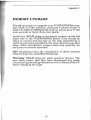
SOFTWARE INSTALLATION
A number of changes have been made to the v1.02 disks shipped with
VGAWONDER. The information given here replaces that given in
7 of the VGAWONDER USER'S GUIDE. The major changes are:
README
Extensively revised. Please read this file before installation.
VSETUP.COM A choice for NEC VGA has been added to ANALOO
SELECTION, which specifies a NEC Multisync 2A or equivalent monitor.
is a new feature to adjust grey scale on a TIL monochrome monitor. Note
each menu choice in VSETUP, you must EXIT, then power-off to write the
to the EEPROM.
VCONFIG.COM A choice for MDA TEXT MODE has been added to allow
monochrome mode without enabling Hercules graphics, i.e. for Sidekick Plus.
VDRIVER.cOM Replaces VINSTALL.COM. This program is used to install
high-resolution drivers.
MOUSE.COM and MOUSKSYS
README for details.
Mouse drivers can now be disabled.
ATI-INFO.COM This is a new program which displays displays cOlilfig'ural
information for diagnostic purposes. If you have occasion to call our
Support Department, please run this program and record the information on
Problem Report.
READMKWIN
installation.
A new text file describing Windows and Windows 286
README.LOT
A new text file describing Lotus] 23 driver installation.
READMKACA
A new text file describing AutoCAD driver installation.
README.SIID
A new text file describing AutoSHADE driver installation.
READMKSKE
A new text file describing AutoSKETCH usage.
README.VP
A new text file describing Ventura driver installation.
READMKGEM A new text file describing GEM driver installation.
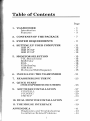
Table of Contents
Page
1. VGAWONDER
Introduction
Features
- 1
- 1
- 3
2. CONTENTS OF THE PACKAGE
- 7
3. SYSTEM REQUIREMENTS
- 9
4. SETTING UP YOUR COMPUTER
IBM PC
IBM PC/XT
IBM PC/AT
-11
- 12
- 13
- 13
5. MONITOR SELECTION
TTL Monochrome
RGB Color
EGA
VGNAnalog
IBM 8514
Mul tis ynclM ul tifreq uency
- 15
- 15
-16
- 16
- 17
-17
- 18
6. INSTALLING THE VGAWONDER
- 21
7. REASSEMBLING THE PC
- 23
8. QUICKSTAUT
(FOR EXPERIENCED USERS)
- 25
H. SOFTWARE INSTALLATION
VINSTALL
VCONFIG
VSETUP
- 27
- 29
- 29
- 3:3
10. DUAL MONITOR INSTALLATION
- 37
11. THE MOUSE INTERFACE
- 39
APPENDIX A
Diagnostics and Troubleshooting
Installation Related Problems
- 41
- 43
- 44
Table of Contents
Page
No Display Problems
Error Messages
Operational Problems
ATI Problem Report Form
- 44
- 45
- 46
- 49
APPENDIX B
Programming Information for
Advanced Users
ATI Enhanced Graphics Modes
Status Detection
Identify VGAWONDER
Memory Configuration
Monitor Configuration
Programming Standard EGANGA
Modes Without BIOS
Selecting Memory Planes
BIOS Compatibility
800x600 - 16 Colors (Mode 54 h)
Video Memory Organization
Video Data Format
640x400 - 256 Colors (Mode 61h)
Video Memory Organization
Video Data Format
640X480 - 256 Colors (Mode 62h)
Video Memory Organization
Video Data Format
800x600 - 256 Colors (Mode 63h)
Video Memory Organization
Video Data Format
1024x768 - 16 Colors (Mode 65h)
Video Memory Organization
Video Data Format
1024x768 - 4 Colors )Mode 67h)
Video Memory Organization
Video Data Format
- 51
APPENDIX C
Memory Upgrade
- 53
- 55
- 55
- 55
- 56
- 56
- 57
- 58
- 58
- 59
- 59
- 60
- 61
- 61
- 61
- 61
- 61
- 62
- 62
- 62
- 63
- 63
- 63
- 63
- 64
- 64
- 64
- 65
- 67
11
Table of Contents
SPECIFICATIONS
Connector Specifications
DB9 Connector
DB15 Connector
Mouse Connector
- 69
-71
-71
-71
-72
FCC COMPLIANCE STATEMENT
- 73
REFERENCE
-75
INDEX
-77
III
IV
VGAWONDER
1
VGAWONDER
INTRODUCTION
The ATI VGAWONDER & VGAWONDER256 are high
performance IBM PCIXT PC/AT 286/386 compatible VGA
video adapters, with capabilities and performance which
exceed other video cards of their type.
They are capable of achieving the 1024x768 resolution of
the IBM Personal Systeml2 high resolution modes on Multisync monitors.
The implementation of both a 16 bit datapath and a 1:1
memory interleave scheme provides the user with fast
screen updates.
100% IBM hardware and software compatibility guarantee the user that their system will be able to run all
software programs written for both the IBM Personal
Computer and the IBM PS/2 Model 30.
1
VGAWONDER
The VGAWONDER is register-level compatible with the
video standards of IBM's MDA: Monochrome Display
Adapter, CGA: Color Graphics Adapter, EGA: Enhanced
Graphics Adapter, VGA: Video Graphics Array, and even
the non IBM standard, the Hercules text and graphics
card standards. Additionally the VGAWONDER supports
resolutions of1024x768, 800x600, 640x480, and 600x400.
The VGAWONDER will operate on practically any IBM
compatible monitor including TTL monochrome, RGB,
EGA, Personal System/2 Analog, IBM 8514, Multisync or
Multifrequency monitors. The adapter is specifically
designed to support the EGA resolution on any of these
monitors and can additionally support the higher resolutions including the 1024x768 on the original Multisync
monitors through interlacing. *
Some of the outstanding features of the VGAWONDER include its ease of installation, with the total elimination of
dip-switches or jumper settings. A Microsoft bus mouse
compatible interface, is included with the adapter,
eliminating the user's requirement to provide an extra
board or device. The versatility of running in either an 8
or 16 bit data bus allows the optimum use of systems.
The VGAWONDER, covered under a Two Year warranty
period, guarantees to give the user the utmost reliability
and performance.
ATI maintains a very high level of technical support which
is readily available to all purchasers of ATI products.
*INTERLACING: used by ATI, has allowed the
VGA WONDER to run high resolution and to display the
high re80lution of l024x768 on monitor8 not normally
capable of displaying this resolution. The visual effect of
interlacing i8 not noticeable on these monitor8.
2
VGAWONDER
FEATURES
The VGAWONDER includes a long list of features:
•
•
•
•
•
Advanced CMOS VLSI Gate Array Technology
The VGAWONDER is built around the exclusive ATI
VGA chip, a solution which features low/ower consumption, high speed performance an complete
reliability, all at a competitive price.
100% Register-Level Hardware Compatibility
VGAcardscan vary in their levels of BIOS or hardware
register compatibility. This may affect their operational capabilities under some software that expect to see
the same registers as with IBM's VGA hardware architecture. The VGAWONDER features 100%
Register-Level Hardware Compatibility to IBM's
VGA. In addition, it includes circuitry that is 100%
register-level compatible with CGA, MDA, EGA, and
Hercules standards.
Includes 512k of Video Memory
The VGAWONDER with 512k of video memory supports higher resolutions with more color. The
VGAWONDER256, with 256K of video memory, supports all the resolutions of the VGAWONDER with a
lower color spectrum and is field upgradeable to 5
Higher Resolution and Enhanced Color Modes
The VGAWONDER supports higher resolutions using
special ATI video drivers. These include 1024x768
with 16 simultaneous colors or 800x600 and 640x480
with 256 simultaneous colors for CAD/CAM, desktop
publishing and presentation graphics applications.
High resolution drivers are included
AutoCAD,
AutoShade, Windows, GEM, Ventura,
Automatic 8/16 bit bus
The VGAWONDER
IBM PC, PCIXT, and
puters. The VGAWONDI<;R will
m a 16 bit slot of an
.
cally configure
an 8 t
VGAWONDER
•
•
•
•
•
Up to 800% Faster than IBM's VGA
With an advanced design using an internal 16 bit
datapath and 1:1 memory access interleave scheme,
performance is up to 800% faster than IBM VGA using
a 16 bit slot and up to 400% faster using an 8 bit slot.
132 Column SupQort
The VGAWONDER supports 132 column text on TTL
monochrome, RGB, EGA, and Multisync or Multifre~uency monitors. Software _presently supported includes Lotus 1-2-3, Symphol!Y, WordStar,
WordPerfect, SmarTerm, Vterm, and NewViews.
User Friendly
Automatic Monitor Detection eliminates setting dip
switches and possible damage to your monitor. The
VGAWONDER detects the monitor at the time the
computer is turned on, and during software re-boot.
A software utilit)' (VSETUP) will help you configure
the VGAWONDER without having to set dip switches;
the onboard EEPROM will store this information after
power down.
Automatic and Manual Video Mode Switching
The VGAWONDER will run all video modes to which
your software application is configured. A software
utility_ (VCONFIG) will manually configure the
VGAWONDER in VGA, EGA, CGA, MDA, or HGC
modes without having to power down the system.
Supports Major Video Standards on Any Monitor
The VGAWONDER will support all software configured for either:
VGA (Video Graphics Array)
EGA (Enhanced Graphics Adapter)
CGA (Color Graphics Adapter)
MDA (Monochrome Display Adapter)
HGC (Hercules Graphics Card)
The VGA WONDER will also support software which
is not normally displayed by some monitors.
4
VGAWONDER
The VGAWONDER runs:
EGA, CGA, MDA, HGC, on an EGA monitor.
EGA, CGA, MDA, HGC, on a TIL monochrome
monitor.
EGA, CGA, MDA, HGC, on an RGB monitor.
VGA, EGA, CGA, MDA, HGC, and ATI enhanced
modes on VGA and Multisync monitors.
•
Improved Text Quality and Monitor Optimization
The resolution of text is improved by the
VGAWONDER. On Multisync, Analog and EGA
monitors, the text of CGA software is improved from
an 8x8 pixel character to a high resolution 8x16 pixels,
and graphics are double scanned.
•
Built-in Mouse
The VGAWONDER includes built-in mouse support
with the inclusion of a Microsoft bus mouse compatible
interface on each board. The configuration of the
mouse to various bus mouse ports or interrupt levels
is provided for using the VSETUP Software.
Flicker Free Operation in All Video Modes
Full Two Year Warranty on Parts and Labour
•
•
5
6
Contents of the Package
2
CONTENTS OF THE
PACKAGE
Your VGAWONDER package includes the following:
•
VGAWONDER Video Adapter or
VGAWONDER256 Video Adapter
•
•
Users manual.
Two software diskettes:
Disk 1 - VGAWONDER Utility diskette.
Disk 2 - VGAWONDER Software Driver diskette.
ATI Microsoft bus mouse compatible (optional).
•
If your package does not include the above items, contact
your dealer immediately.
If you are installing the VGA WONDER on a system which
requires 3.5" diskettes, please call ATI with the serial
7
Contents of the Package
number of your card and we will be pleased to send the appropriate disks, or contact your dealer to have the software
downloaded to your diskette standard.
Be sure to make working copies of the original diskettes
to prevent accidental erasure of important files.
Completion of your warranty card, which is contained at
the back of this manual, is important in order to maintain
your warranty and receive Technical Support services
from ATI Technologies Inc.
You have purchased a video card of the highest quality.
Engineered by ATI Technologies, this card will maintain its quality for many years.
NOTE: The VGA WONDER256 has been engineered with
provisions for upgrade to 512K video memory. Information
required to upgrade the VGA WONDER256 to 512K of
video memory is contained in Appendix "C".
8
System Requirements
3
SYSTEM
REQUIREMENTS
The VGAWONDER is designed for use in any open system
expansion slot in an IBM or compatible/AT system which
uses a 16 bit data path slot on its motherboard, however
the user may also find it quite suitable for use with an IBM
or compatible 8 bit bus slot motherboard, or the IBM System/2 Model 30. If you are installing the VGAWONDER
in an 8 bit slot, care should be taken to ensure that the
"gold fingers" do not hit any components which are in its
path, when the board is being installed. A suitable slot can
normally be found.
NOTE: If you are uncertain of a suitable slot, we recommend that you have an experienced technician install the
card. ATI does not cover under, its warranty, any damage
caused either to the card or the system by the incorrect installation of this card.
9
System Requirements
Under no circumstances should the card be installed while the system is switched on.
supported by the VGAWONDER will be
covered in Chapter 5 "Monitor Selection". Users should
be familiar with the capabilities oftheir monitor before installation. ATI recommends the use of a Multifrequency
monitor in order to obtain the optimum results of the
VGAWONDER, however the VGAWONDER has more
capabilities wi th other monitors than other VGA cards and
therefore the user is not specifically restricted to any particular monitor in order to achieve better than average
results.
The IBM Personal Computer and Personal System/2 do
not permit two similar display adapters to reside in the
system operating in the same mode. The VGAWONDER
has multiple emulation capabilities, which are controlled
by a user software program supplied with the
VGAWONDER.
NOTE: It is recommended that other uideo adapters which
installed in the system, or which may
prouision on the motherboard, be
or disabled before installing the
your system.
on the installation of dual
Chapter 10 "Dual Monitor Selec-
10
Setting Up Your Computer
4
SETTING UP YOUR
COMPUTER
In order to install the VGAWONDER It may be necessary
to make some minor changes to the switch settings on the
computer system. If you do not feel comfortable in making
these changes you should consult a qualified Computer
Technician. Installing the VGAWONDER is very simple
and can be achieved in 15 minutes or less.
Read the following instructions before you start.
NOTE: Static electricity can seriously damage the components in your computer. You must ensure that you have
discharged any static electricity by grounding yourself to
the chassis of the pc before you begin.
11
Setting Up Your Computer
IBM/PC
Ensure that the System is switched off and the power
cord removed before installation. Damage to the System
and the VGAWONDER may result if the power is left
on.
Remove the 5 cover mounting screws from the rear of the
PC.
On the IBM/AT you must unlock the keylock before you
can remove the cover.
Some compatible PC's have a hinged top for convenience.
If your system appears to be different, consult your System Users Manual for instructions on board installations.
On the IBM Personal System/2 Model 30 remove the 4
cover mounting screws, 2 of them are located on each side
of the system.
Carefully slide the cover forward, until it will go no further, then tilt the cover away from the system unit and
withdraw it from the system.
On the Personal System/2 Model 30, slide the cover backwards and remove by lifting straight up.
Put the screws in a safe place, you will need them later for
re-installation.
There are no switches or jumpers to set on the
VGA WONDER, the card will automatically configure itself to your system upon installation.
It is however necessary to configure your system
for the card.
The correct configuration of your system is the
samc as for that of an EGA card.
See diagram on the following page.
12
Setting Up Your Computer
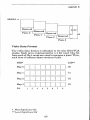
IBMPCIXT
Switch Settings
IBM PC/XT Switch Block 1
I I I I 1.1.1 I I
OFF/OPEN
ON/CLOSED
2345678
When installing the VGAWONDER in an IBM PC, PCIXT,
set switches 5 & 6 as outlined in the above table. Do not
change any other switches as these will affect the
memory and configuration of your system.
NOTE: Do not use a pencil to set the switches, as the
graphite residue can damage your computer.
The PCIXT has only one switch block on its motherboard;
which should be easy to find. Compatibles may have different switch locations or set-ups in order to isolate their
video interface. Consult your Systems User Manual for
these locations.
IBMPCIAT
When installing the VGAWONDER in the IBM PC/AT it
is necessary to set the video display switch (ColorlMono
switch) on the AT motherboard to Color and run the IBM
Advanced Diagnostics Program which will automatically configure the System for an EGA (Enhanced
Graphics Adapter) Card, which is the category for the VGA
WONDER.
13
14
Monitor Selection
5
MONITOR SELECTION
AUTOMATIC MONITOR DETECTION
It is manditory that the monitor is connected to the
VGAWONDER before power-up in order for the automatic
detection to function correctly. Failure to do this will result
in an incorrect monitor being detected.
The VGAWONDER will support the following IBM compatible video monitors in text & graphics resolution as
follows:
TTL MONOCHROME (1S.43KHz)
These monitors are designed to be used with Hercules or
MDA cards. With the VGA WONDER, the following
software standards can be displayed:
- Monochrome text mode
- Hercules text and graphics modes 720x348
15
Monitor Selection
- RGB text and graphics mode 320x200 - in shades
- EGA text and graphics mode - 640x350 in shades
- 132 Columns x 44 rows text for software which either
supports this mode or by drivers which are provided
by ATI on the disks supplied with the card.
RGB COLOR (15. 75KHz)
These monitors are designed to work with CGA cards.
With the VGAWONDER, the same standards as with the
TTL monochrome are displayed with the following differences:
- CGA and EGA are displayed in colors instead of
shades;
- 132 Col umns x 25 rows text for software which either
supports this mode or by drivers which are provided
by ATI on the disks supplied with the card.
It should be noted that in order to display the EGA or Her-
cules resolution on RGB monitors an interlacing technique
is used. This will result in some "flickering" of the image
on the screen on this particular monitor. Flicker can be
reduced by the use of an anti-glare filter or by decreasing
the contrast and brightness controls. This monitor is not
recommended as being suitable for prolonged use in these
resolutions.
EGA (15.75 - 21.85 KHz)(Enhanced Graphics Monitors)
Enhanced Graphics monitors are designed to work with
CGA or EGA cards. Using the VGAWONDER, EGA
monitors can display:
- Hercules text and graphics modes 720x348
RGB graphics mode - 320x200 - 16/64 colors.
- EGA text and graphics modes - 640x350 - 16/64
colors.
16
Monitor Selection
- 132 Columns x 44 rows text on software which either
supports this mode or by drivers which areprovided
by ATI on the disks supplied with the card.
VGAfANALOG MONITORS (31.5KHz) (sometimes
referred to as PS /2 color or monochrome display)
The Analog monitor has an advantage in displaying an infinite array of colors. In VGA it is possible to display up to
262,144 colors.
In addition to displaying the same modes as with an EGA
monitor, the VGAlAnalog monitor will allow the following
modes:
- All 17 of the IBM VGAlAnalog modes, displaying
color spectrums of 256 colors from a palette of
262,144 where the modes are defined to support this
choice.
- Additionally supporting Hercules, CGA, EGA, and
the higher resolution ATI modes of 640x480 in 256/
262,144 colors on software supported QY the drivers
which are included by ATI with the VGAWONDER
or by the software manufacturer to support this
resolution.
IBM 8514 (43.5KHz) (or compatible)
The IBM 8514 monitor is a high resolution color Analog
monitor that is VGA compatible and also operates in interlaced mode. The 8514 will allow the use of an addi tional
mode, in addition to, the modes functional on VGAlAnalog
monitors:
- Supporting the higher resolution of 1024x768 in
16 colors from a palette of262,144.
- Additionally supporting IBM VGA, Hercules, CGA
and EGA modes.
17
Monitor Selection
MULTISYNC OR MULTIFREQUENCY MONITORS
Some introduction is required in defining these monitors.
These monitors have a range of operating frequencies and
will adjust to the output frequency of the graphics adapter. Some models of the Multisync or Multifrequency
monitors may not have the capability to display 1024x768
because of their lower operating frequency range.
ATI recommends that the Multisync or Multifrequency
monitor is used in the Analog mode for optimum results
with the VGAWONDER. This is achieved by using a 15
pin VGAJAnalog connecting cable from the monitor to the
VGAWONDER and switching your monitor to ANALOG.
NOTE: Refer to the Operating Manual of the Monitor for
more details or call your dealer to obtain the necessary
cables and adapters if required.
Multifrequency monitors support the following resolutions using the VGAWONDER:
- Hercules text & graphics modes 720x348
- RGB graphics mode" 320x200 - 16/64 colors.
- EGA text & graphics modes - 640x350 - 16/64 colors.
- 132 columns to a maximum of 60 rows text on
software which either supports this mode or by
drivers which are included by ATI, on the disks supplied with the VGAWONDER card.
- All the IBM 17 VGAJAnalog modes, displaying a
color spectrum of up to 256 colors from a palette of
262,144.
18
Monitor Selection
The VGAWONDER also supports higher resolution AT!
modes:
- 640x400 in 256 from 262,144 colors.
- 640x480 in 256 from 262,144 colors.
- 800x600 in 256 from 262,144 colors.
- 1024x768 in 16 from 262,144 colors.
with software supported by the drivers which are included
by ATI with the VGAWONDER or by the software
manufacturer to support this resolution.
NOTE: If you have a Multisync nwnitor without a 15 pin
VGA / Analog cable etc., contact the Monitor manufacturer
or their representative for details on adapter cables.
19
20
Installing The VGAWONDER
6
INSTALLING THE
VGAWONDER
The VGAWONDER is a 16 bit databus/datapath card, that
is to say that it has been designed to take full advantage
of the wider datapath of systems using the 80186, 80286
or 80386 microprocessor which is found in the IBM!AT systems or compatibles. This gives the advantage of much
faster speeds and optimizes the system. The card will
however run in an 8 bit databus slot found in the IBM PC
or XT and compatibles. The user should be aware that
when installing the card in the shorter or 8 bit slot a portion of the "gold fingers" connector on the VGAWONDER
will not be connected into any part of the expansion slot.
Care should be taken to ensure that this portion of the connector, which is not connected to your expansion slot, does
NOT touch any components on your mother board.
NOTE: ATI Technologies will not be responsible in any
way for damage which is caused to either the system or the
card because of incorrect installation.
21
Insullling the VGA WONDER
For IBM/AT users the VGAWONDER should be installed
in a 16 bit slot.
For IBMfX'f users the VGAWONDER should be installed
in a slot where the extending "gold fingers" are clear of
components on the mother board.
Remove the slot cover at the rear ofthe system and grasping the card by the top edge, firmly locate it into the
expansion slot.
Insert the screw from the expansion slot cover in the hole
at the top of the VGAWONDER's retaining bracket and
tighten it.
Replace the System Unit's cover and fasten the screws.
You should now connect a monitor to the card with the
use of a properly shielded cable. There is provision on the
VGAWONDER for both a 9 pin and a 15 pin connector.
The 9 pin connector is for use with TTL monitors, and the
15 pin connector is for use with VGA, Multifrequency or
Multisync monitors.
The monitor must be connected to the
VGAWONDER before you switch on your system in
order to be properly identified by the ATI Monitor
detect program.
Warning: Only one monitor can be attached to the
VGA WONDER card at any time, otherwise damage to one
of your monitors might result.
NOTE: Ifyou do not have the appropriate 15 pin VGA cable
{or your Multisync or Jl.1ultifrequency monitor, it should be
available through your local Computer Dealer.
If you have correctly installed the VGAWONDER your
system is now ready to run, however you are advised to
read Chapter 9 "Software Installation" before proceeding.
22
Reassembling The PC
7
REASSEMBLING THE
PC
Replace the cover on the PC and replace the screws at the
rear.
Using the properly shielded cable attach the monitor to
the VGAWONDER adapter.
The System is now ready to run.
In order to test the full operational functionality of the
VGAWONDER, a Utility program named VGATEST is
provided by ATl on the diskette supplied with the card.
Follow the menu driven instructions; and a series of
screens will be displayed. If these screens are displayed
correctly, the VGAWONDER has been properly installed
and is in good working order.
For more information on VGATEST, see Appendix A.
23
24
Quick Start
8
QUICK START
(FOR EXPERIENCED
USERS)
This Chapter can be used as a guide to Quick Set-Up for
the experienced user. It should not be used unless you
have a full understanding of how to install a card.
Unplug computer and remove the cover.
Remove any video cards and install the VGAWONDER
into any available slot (8 bit or 16 bit slot). Seat the
VGAWONDER and secure with a mounting screw.
For IBM PC and PCIXT users, set switches 5 and 6 on
switch block 1 to the "ON/CLOSED" position.
For IBM AT and compatible users, if applicable, set the
video selection s,vitch or jumper to the "COLOR" position.
25
Quick Start
Reinstall cover of computer and connect power cord.
Connect monitor to video connector on the back of the
VGAWONDER. Multisync or PS/2 monitors should use
the analog port (DB-15). EGA, RGB, or TTL monochrome
monitor should use the digital port (DB-9).
Turn on the computer. IBM PC/AT or compatible owners
should run the "setup" program on the PC/AT Diagnostics
Disk to ensure that the system has selected a color card
as the primary card.
NOTE: Do not change monitors after you have
powered up. Serious damage could result.
Using the VGAWONDER UtiJitydiskette, run VINSTALL
to install the ATI software utilities and high resolution
drivers onto your hard disk.
You are now ready to enjoy a new world of high performance, high resolution video.
26
Software Installation
9
SOFTWARE
INSTALLATION
The VGAWONDER is shipped with software utilities to
change the default settings and a variety of high resolution drivers enhancing the operation of graphics programs
such as GEM, Windows, and AutoCAD. Although the
VGAWONDER will work without any further input, it is
recommended that you go through the software installation process to get peak performance from your video
board.
27
Software Installation
The VGAWONDER
utilities:
ATIVIDEO.SY
DATE.COM
CLR.COM
Diskette #1 contains the following
- RAM version of video BIOS
- utility that checks date of BIOS
- clear screen utility for 132 column
mode
- 43 line mode utility
L43.COM
- addendum and driver installation
README
instruction
- mode switching software
VCONFIG.COM
- diagnostic
software
for
VGATEST.COM
VGAWONDER
VINSTALL.EXE
- run this program to install ATI's
software utility on your hard disk
VSETUP.COM
- setup and configuration utility
GAMES
<DIR> - subdirectory with instructions to
run some special game programs
- the ATI standard mouse driver
MOUSE.COM
compatible with Microsoft
mouse.com
- the alternative driver conforming
MOUSE.SYS
to DOS installable drivers
VGAWONDER Diskette #2 contains the following drivers:
<DIR> - subdirectory with AutoCAD
drivers
with GEM version 2
subdirectory
GEM
<DIR> & 3 drivers
LOTUS
<DIR> - subdirectory with Lotus drivers
VENTUHA <DIR> - subdirectory with Ventura drivers
WINDOWS <DIR> - subdirectory with Windows driver
ACAD
Software Installation
VINSTALL
To start the installation process for the VGAWONDER
Utilities, insert the VGAWONDER Utility diskette into
drive A and type:
A> VINSTALL <enter>
The following menu will appear on your screen:
*** VGA WONDER Software Installation Menu (ver xxx) ***
ver
AutoShade ver 1.0
AutoSkctch ver 1.04
GEM ver 2.1/ ver 2.2/ ver 3.0
Lotus 1-2-3 vcr 2.0
Symphony ver 1.1
Ventura ver 1.0/ver 1.1
Windows ver 1.03/ ver 1.04/ vcr 2.03
LV"--£UJ
3.
4.
5.
6.
7.
8.
9.
Use <i ,1> or < letter> and < ret> to select option, < esc> to
abort.
For further detailed information on the submenus contained within the VINSTALLmenu, consult the README
file.
VCONFIG
VCONFIG is a menu driven, user friendly utility that is
used to:
1.
Change the current video mode to a different
mode;
2.
Automatically turn your screen display off
during long periods of inactivity;
29
Software Installation
VCONFIG is autom.atically copied onto your hard disk
drive or your boot disk during the installation process.
To start VCONFIG, type at the DOS prompt:
C> VCONFIG <enter>
The following menu will be displayed:
ATI TECHNOLOGillS INC ATI TECHNOLOGIES INC A
TI TECHNOLOGIES INC ATI TECHNOLOGIES INC AT
I TECHNOLOGIES INC ATI TECHNOLOGIES INC ATI
© COPYlUGHT 1988
MODE
SELECTION
VGAWONDER ADVANCE CONFIGUHATION PIWGHAM
SETUP
VEHSION XXX
SELECTION
[Bl
[el
[D]
[E]
[F]
[G]
lH]
[I]
[Jl
[L]
KEYWOHDS
EGA
eGA
MDA MONO GHAPHICS 720x340
MDA MONO GHAPHICS 640X400
132x25
132x44
132x60
SCREEN SAVE
8/16-BIT SELECT
EXIT
EGA
CGA
H720
H640
25
44
60
SAVE
Current configuration
Monitor detected
VGA in cv80
EGA
Use <i J,> or < letter> and < ret> to select option,
< esc> to abort.
Each of the options in VCONFIG can be selected by typing
in the letter to the left of the selection and then depressing the <enter> key. As you get familiar wi th the operation
of VCONFIG, you can bypass the menu completely by
typing:
C> VCONFIG lKEYWORD 1<enter>
30
Software Installation
The keywords are indicated on the right hand side of the
screen: VGA, EGA, CGA, H720, H640, 25, 44,60, or SAVE.
A description of each of the options under VCONFIG follows:
[A] VGA
This option selects the VGA mode and is functional only
with VGA, 8514 and Multisync monitors. Software configured for VGA mode will run under this mode.
[B] EGA
This option selects the EGA mode and is functional on all
monitors. Software configured for EGA mode will run
under this mode.
[C] CGA
This option selects the CGA mode. ATI enhances this mode
by improving the graphics and text to a double scanned
image on all monitors except for RGB monitors.
[D] MDA MONO GRAPHICS 720x348
Selection of this option will put the VGAWONDER into
Hercules Graphics mode. If you are using a color monitor,
you will have a choice of text colors from white, amber or
green. All Hercules graphics programs use this resolution.
[E] MDA MONO GRAPHICS 640x400
This option will put VGA WONDER into special Hercules
Graphics mode. Only a small number of programs use this
resolution. If you have a problem with this option, try option [D J.
[F] 132x25
The option 132 column x 25 row text mode works on all
monitors except VGA monitors.
[G] 132x44
The 132 column x 44 row text mode will work on all
monitors except for RGB monitors and VGA monitors.
rH] 132x60
This option will only work on Multisync monitors.
31
Software Installation
NOTE: 132 Column modes can only be used by software
which is written to support 132 columns on the screen.
Check your users manual or call your dealer to confirm
that the application will run in this mode.
[I] SCREEN SAVE
The Screen Save option will activate a utility which will
turn offthe screen display after a predetermined time interval in order to prevent accidental phosper etching on
your monitor. At your option, Screen Save is automatically installed during the utility installation process.
NOTE: Screen Save is not compatible with graphics
programs that run under the GEM or Windows environments. Type "VCONFIG SA VE OFF" before you start these
programs, and type "VCONFIG SA VE ON" after you leave
these programs. You can also incorporate these commands
into a batch file to have the command automatically executed.
[J] 8/i6-BIT SELECT
8 or 16 bit BIOS operation. In an IBM XT, 8 bit is selected
automatically. In some AT systems the VGAWONDER
may not operate correctly in the 16 bit mode. This will be
obvious if the system is NOT responding to keyboard control. ATI recommends that the user select the 8 bit mode
if this condition persists.
[K] EXIT
Selection of this option will execute the last mode chosen
that is supported by the monitor you are using. If you do
not use EXIT to leave the menu, all options you choose will
be ignored.
32
Software Installation
VSETUP
VSETUP is used to configure the onboard EEPROM. The
setup information is retained even after the power is
turned off. It is also used to change or store the default information used by the VGAWONDER. It is only necessary
to use VSETUP in the following situations:
1. To change the default setup video mode.
2. To specify default monitor selection on powerup.
3. To setup the mouse interface.
To start VSETUP, type at the DOS prompt:
C> VSETUP <enter>
The following menu will be displayed:
ATl TIWHNOLOGIES INC ATI TECHNOLOGIES INC A
T! TECHNOLOGIES INC ATI TECHNOLOGIES INC AT
I TECHNOLOGIES INC AT! TECHNOLOGIES INC ATI
© COPYRIGHT 1988
VGAWONDER ADVANCE SETUP PHOGHAM
VSETUP
VEHSION X.xx
POWEH UP MODE SELECTION
.[jAl········~At6dM6i'iIl'dJ1~tltbl'I6r.J···<····
[C]
[D]
[EJ
lFJ
lGJ
lHJ
III
EGA
CGA
MDA MONO GRAPHICS 720X348
MDA MONO GRAPHICS G40X400
8/IG BIT SELECT
MOUSE OIYJ'ION SELECT
EXIT AND SAVE CONFIGUHATION
Monitor detected
EGA
Use < 1'1, > or < letter> and < ret> to select option, < esc>
-to
. abort.
--
The following is a description of the VSETUP menu:
33
Software Installation
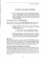
[A] ANALOG MONITOR SELECTION
The VGAWONDER monitor detection circuitry cannot differentiate between Multisync, Multisync Plus, or
Multisync XL monitor. You must specify which type of
multisync monitor is attached. This selection allows you
to override the automatic analog monitor detection function of the VGAWONDER.
[B] VGA
Selection ofthis item will start the VGAWONDER in VGA
mode, and is operational only with Analog and Multisync
monitors. Similar to the VCONFIG menus, you will be
given the option of choosing either the COLOR or MONO
option; if you have a color monitor, and you choose the
MONO option, another menu will appear, asking for the
choice offoreground color (either white, amber or green).
[C] EGA (and Dual Monitor Configurations)
Selection ofthis item will start the VGAWONDER in EGA
mode.
You will be given the option of choosing either the
EGA(C80), EGA (CE80), EGA (M80) or DUAL option. If
you have a color monitor and you choose the EGA (M80)
option, another menu will appear, asking for the choice of
foreground color (either white, amber or green).
Dual Monitor
If you select the DUAL option, you must determine which
video card you wish to be the primary card at the time the
computer powers up.
Primary Card - VGAWONDER
If you elect to have the VGAWONDER be the primary
video card you can choose from the first three options:
1. With an MDA or Hercules card as the secondary
adapter, you have the option of the
VGAWONDER powering up as:
34
Software Installation
a) CGA card - choose EGA (C80)IMDA
b) EGA card - choose EGA (CE80)IMDA
2. With a CGA card as the secondary adapter,
choose EGA (M80)/CGA (VGAWONDER powers
up as a Hercules or MDA card); you will also
have to specify your selection of a foreground
color if you are using a color monitor on the
VGAWONDER.
Secondary Card - VGAWONDER
If you elect to have the VGAWONDER be the secondary
video card, you can choose from the last three options:
1. With an MDA or Hercules card as the primary
adapter, you have the option of the
VGAWONDER as:
a) CGA card - choose MDA/EGA (C80)
b) EGA card - choose MDA/EGA (CE80)
2. With a CGA card as the primary adapter choose
CGA/EGA (M80); you will also have to specify
your selection of a foreground color if you are
using a color monitor on the VGAWONDER.
[D] CGA
Selection of this item will start the VGAWONDER in CGA
mode with double scanned text. Because this mode has the
lowest resolution available on the VGAWONDER, ATI
recommends using this mode as a default only if the
majority of your software is CGA selfbooting software.
[E] MDA MONO GRAPHICS 720x348
Selection of this item will start the VGAWONDER in Hercules mode. ATI recommends using this mode as a default
only if the majority of your software is monochrome. If you
are using a color monitor, when you select this option, you
will be required to choose a color (either white, amber or
green). Almost all Hercules Graphics programs use this
resolution.
35
Software Installation
[F] MDA MONO GRAPHICS 640x400
This selection will also start the VGAWONDER in a special Hercules mode. However, only a small number of
Hercules graphics programs use this resolution. If there
is a problem with this option, try option [E].
[G] 8/16 BIT SELECT
Select 8 or 16 bit BIOS operation.
[H] MOUSE OPTION SELECT
The Mouse option select allows the user to:
- Select or deselect the mouse
- Select the interrupt level
- Select Primary or Secondary mouse port
The default setting for the ATI Mouse is deselected.
[J] EXIT AND SAVE CONFIGURATION
This option records the last configuration sequence into
the EEPROM. If you do not use this option to leave
VSETUP, the configuration information is not saved.
36
10
DUAL MONITOR
INSTALLATION
The VGAWONDER will co-exist with 3 types of video
adapters: either MDA, Hercules Graphics or eGA card.
Other video adapters will not work with the
VGAWONDER.
You must select which card will be the primary or startup video adapter. ATI recommends that you use the
VGAWONDER as the primary adapter because of its superior performance and flexibility.
Make the following switch selections:
For IBM PC, and PCIXT, set switch 5 and 6 on switch
block 1, both to the ON position.
37
Dual Monitor Installation
For IBM PC/AT If equipped with display switch, consult
owner's manual for more information, set the display
switch to the COLOR position.
IBM PC/AT owners must run the IBM Diagnostics
"SETUP" provided with the computer. (Consult your
owner's manual for more details). Select the NO DISPLAY
or EGA option.
Now run ATI VSETUP, as described in Chapter 9.
To change between the primary and secondary adapters,
use the MODE command found on your DOS diskette. At
the DOS prompt, type:
A> MODE [KEYWORD] <enter>
where the keyword is C080 or MONO.
NOTE: In dual monitor configurations, you can use
VCONFIG to change the current mode. However, the
VGA WONDER cannot emulate MDA or Hercules if an
MDA or Hercules card is installed in the system. Similarly, the VGA WONDER cannot emulate a CGA, EGA or VGA
if a CGA is installed in the system. ATI does not recommend the use of a color card with the VGA WONDER Since
many of the color modes on the VGA WONDER would be
defeated.
38
The Mouse Interface
11
THE MOUSE
INTERFACE
The Mouse Interface is compatible with the Microsoft bus
mouse interface.
The configuration of the mouse interface is programmed
via the VSETUP and VCONFIG utilities. VSETUP determines the default power-up configuration and VCONFIG
is used to change the configuration after the system is
power on.
The mouse configuration parameters are the interrupt
level and the port address of the mouse interface.
39
The Mouse Interface
An Interrupt Request (IRQ) is generated when a hardware
device (such as the mouse interface) needs service from
the pc system. You should set your mouse interface so that
it uses an IRQ level not used by any other device in your
pc system.
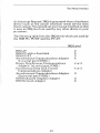
The following table lists the IRQ levels which are used by
the IBM PC, PCIXT and the PC AT.
IRQ Leyel
IBM AT
IBM PC with a fixed disk
IBM PCIXT
Asynchronous Communications Adapter
(1st serial port COM1):)
Binary Synchronous Communications
Adapter (lst serial port COM1:)
Synchronous Data Link Control
Communications Adapter
Asynchronous Communications Adapter
(2nd serial port COM2:)
IBM Enhanced Graphics Adapter
IBM Network Adapter
40
2
5
5
4
4 or 3
4 or 3
3
2
2
Appendix A
APPENDIX A
41
42
Appendix A
DIAGNOSTICS AND
TROUBLESHOOTING
The VGATEST diagnostics program should be used when
the VGAWONDER produces a display, but does not work
properly. For example:
•
•
does not display graphics,
has missing characters,
•
•
has no color,
does not display in all modes.
Follow the menu driven instructions and a series of
screens will be displayed. If these screens are displayed
properly, the functions of the VGAWONDER are in good
working order.
If problems are still encountered after the VGAWONDER
passes VGATEST, they are most likely installation, compatibility or operation related.
Compatibility related problems can be isolated by trying
the VGAWONDER on another monitor and/or another
computer as appropriate.
43
Appendix A
INSTALLATION RELATED PROBLEMS
NO DISPLAY PROBLEMS
•
Problem:
Cannot seat VGAWONDER into slot.
Diagnosis:
Components in computer may interfere.
Action:
Try a different slot.
•
Problem:
No display, No fan noise.
Diagnosis:
No power to computer.
Action:
Check that computer is Rlugged in and turned on. If
the power indicator light iloes not come on when power
is switched on, the power supply may be defective.
•
Problem:
No display, fan noise, computer beeps (1 long and 2
short tones)
Diagnosis:
Video card not recognized.
Action:
Check switch settings: switches 5 & 6 on switch block
Ion your motherboard should be "ON". Check that the
VGA WONDER is properly seated in the slot.
Check ROM BIOS date (IBM PC only). Get new BIOS
if earlier than 10/16/82.
44
Appendix A
•
Problem:
No display, computer beeps once, floppy drive light
flashes on and goes off.
Diagnosis:
Com pu ter works, signal not reaching monitor, possible
defective monitor.
Action:
Check monitor; is it switched on and monitor cable connnected properly.
Turn up monitor brightness and contrast controls.
Turn monitor off and on, then reboot system.
Try monitor on another system.
•
Problem:
No display, dual monitor configuration.
Diagnosis:
Incorrect installation
Action:
Check installation, run VSETUP.
If problem not solved, remove other video card and
install VGAWONDER as single monitor setup to confirm operation before attempting dual mom tor configuration.
ERROR MESSAGES
•
Problem:
Error message - 'Invalid configuration press Fl to continue.' (IBM PC/AT only).
Diagnosis:
Incorrect configuration file, or dead AT battery.
45
Appendix A
Action:
Run AT diagnostics software, installing for EGA or No
Display; reboot; problem should disappear; power
down, if problem appears on power up again,
battery is dead.
•
Problem:
Error message - Failed VGATEST
Diagnosis:
Certain modes may not operate on certain monitors.
Action:
Check section on monitor selection. If the mode is supposed to run, and colors or patterns are missing, card
may be defective.
OPERATIONAL PROBLEMS
•
Problem:
Screen goes blank in Windows, GEM or games
Diagnosis:
Program incompatible with SCREEN SAVE.
Action:
Disable SCREEN SAVE, by typing, 'VCONFIG SAVE
OFF' at DOS prompt before using program.
•
Problem:
Software does not work or garbage appears
and system hangs.
011
screen
Diagnosis:
Software mode incorrect or not supported by monitor.
Action:
Use VCONFIG to change mode to match what
software is installed for. Check that mode is supported
by your monitor.
46
Appendix A
Diagnosis:
Possible device driver or memory resident program
conflict.
Action:
Disable programs by: unloading them from memory or
qy renaming the AUTOEXEC.BAT file to *.BAK and
CONFIG.SYS to *.BAK and reboot. If the problem disappears, there is a conflict with one of your programs.
Diagnosis:
Monitor may not switch modes without resetting.
Action:
Reset monitor by turning it off and on.
•
Problem:
Memory resident programs (ie. SideKick) work when
initially loaded, but not later when needed.
Diagnosis:
Current video mode different from installation ofTSR
program.
Action:
Use VCONFIG to switch mode to whatever the TSR
program (ie. SideKick) is installed for.
•
Problem:
Programs vary in screen size.
Diagnosis:
Programs may be using different video modes.
Action:
Adjust the horizontal and vertical height controls on
your monitor.
•
Problem:
Screen flickers on RGB monitor.
47
Appendix A
Diagnosis:
Interlacing of image.
Action:
Use a screen filter or install software for lower resolution.
Ifnone ofthe above have helped to solve the problem, contact the dealer who sold you the computer or
VGAWONDER. If they are unable to solve the problem,
fill out the ATI Problem Report form, located on the following pages, and call our Technical Support Department.
•
The Technical Support Departement is open between the hours of 9:00 am and 5:30 pm Eastern
time at (416) 756-0718.
48
Appendix A
A TI Problem Report
Before calling ATI Technical Support please fill out this
form and have it available when talking to one of our representatives. This form must be filled out before placing
the call to ATI. If you write, please complete both pages of
this report and mail to the address given on the back of
this manual or fax to 416-756-0720.
ATI WILL BE UNABLE TO PROCESS YOUR CALL
WITHOUT THIS INFORMATION.
Serial Number:
VGAWONDER
CJ
VGAWONDER256
VGA BIOS Version*: - - - -
CJ
DOS Version: - - -
VCONFIG version: _ _ _ _ VSETUP version: _ _ __
Type & Model ofComputer: ____________
Type & Model of Monitor: _ _ _ _ _ _ _ _ _ _ __
Other Add-on Boards Installed and Version: - - - - Memory Board: _ _ _ _ _ _ _ _ _ _ _ _ _ _ __
Mouse (Make):
-----
Network (MakelModel):
Driver Version: - - - -
---
Software & Version:
Memory-Resident ProgramslDevice Drivers Loaded
(Versions) :
* BIOS Version is displayed on the screen upon power up or by funning BIOSDATE on Disk Ill.
49
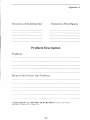
Appendix A
Contents of Autoexec.bat
Contents of Config.sys
Problem Description
Problem:
Steps to Re-Create the Problem:
ATI TECHNICAL SlJPPORT DEPARTMENT: (416) 7S6-07Ul
IIOURS: 9:00allllo 5:30pm Est.
50
Appendix B
APPENDIXB
51
52
Appendix B
PROGRAMMING INFORMATION FOR
ADVANCED USERS
The ATI VGAWONDER is a high-speed, high-resolution
video card for the IBM PC, XT and AT series personal computer market. It offers the utmost in compatibility being
the only product on the market that is 100% register and
BIOS compatible with VGA, EGA, CGA, MDA and Hercules. It supports every mode of these 5 video standards
on compatible monitors. In many cases, the
VGAWONDER will support video modes not normally
supported on some monitors. For instance, EGA hi-res and
Hercules modes on an RGB monitor or EGA and CGA on
a monochrome TTL monitor. In addition, the
VGAWONDER will support a number of ATI exclusive
video modes. This document details information that
software developers will require to program the card in
these ATI modes. Developers who require programming
information about standard IBM or Hercules video modes
should refer to the Reference, located on page 75.
The VGAWONDER incorporates a number of video display modes on one board, care should be taken when
programming to avoid video memory conflict and/or
programming to the wrong display mode. Damage to the
monitor may result if wrong mode parameters are
programmed. Read through this section and the example
program before attempting to program for the
VGAWONDER.
53
Appendix B
AH=O
AL=
Oh
1h
2h
3h
0*
1*
2*
3*
0+
1+
2+
3+
4h
5h
6h
7h
Odh
Oeh
Ofh
10h
11h
12h
13h
;set video mode
MODE/
TYPE
color/al pha
color/alpha
color/alpha
color/alpha
color/alpha
colorfalpha
color/alpha
color/alpha
color/alpha
color/alpha
color/alpha
color/alpha
color/graphics
color/graphics
colorfgra~hics
mono/alp a
color/graphics
color/graphics
mono/graphics
color/graphics
color/i5raphics
color/graphics
color/graphics
RESOLUTION DIM/
COLOR
START
ADDRESS
640x200
640x200
640x200
640x200
640x350
640x350
640x350
640x350
720x400
720x400
720x400
720x400
320x200
320x200
320x200
720x350
320x200
640x200
640x350
640x350
640x480
640x480
320x200
40x25/BW
40x25/ 16
80x25/BW
40x25/ 16
40x25/BW
40x25/ 16
80x25/BW
80x25/ 16
40x25/BW
40x25/ 16
80x25/BW
80x25/BW
40x25/ 4
40x25/BW
80x25/BW
80x25/BW
40x25/ 16
80x25/ 16
80x25/BW
80x25/ 16
80x30/BW
80x30/ 16
80x25/256
b800:0h
b800:0h
b800:0h
b800:0h
b800:0h
b800:0h
b800:0h
b800:0h
b800:0h
b800:0h
b800:0h
b800:0h
b800:0h
b800:0h
b800:0h
bOOO:Oh
aOOO:Oh
aOOO:Oh
aOOO:Oh
aOOO:Oh
aOOO:Oh
aOOO:Oh
aOOO:Oh
*1056x350
*1056x350
1056x350
1056x350
132x25/ 16
132x25/BW
132x441 16
132x441BW
b800:0h
b800:0h
b800:0h
b800:0h
ATI Enhanced Modes
23h
27h
33h
37h
colorfal pha
mono/alpha
color/al pha
mono/alpha
54h
61h
62h
63h
65h
67h
color/graphics
color/h'Taphics
color/h'Taphics
color/h'Taphics
color/h'Taphics
color/gTuphics
800x600
640x400
640x480
800x600
1024x768
1024x768
16
256
256
256
16
4
aOOO:Oh
aOOO:Oh
aOOO:Oh
aOOO:Oh
aOOO:Oh
aOOO:Oh
The ATI enhanced mode 61H, 62H, 63H, 65H, and 67H
are supported by the set mode (ah = 0) function only, the
other BIOS functions will not support these modes. It is
up to the application programs or drivers to implements
those functions.
'I:
On ROB monitors, a resolution of l056x200 is auailable.
54
Appendix B
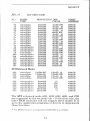
ATI ENHANCED GRAPHICS MODES
The video modes described in this document are listed
below by the BIOS video mode number. We highly recommend that programmers select the video mode through
BIOS whenever possible.
Mode# Resolution
(hex)
54
61
62
63
65
67
800x600
640x400
640x480
800x600
1024x768
1024x768
Colorsl
Palette
16/256K
256/256K
256/256K
256/256K
16/256K
4/256k
Memory
Required
256K
512K
512K
512K
512K
256k
Monitors
Supported
3
1,2,3
1,2,3
3
2,3
2,3
Monitor Chart 1) VGA, 2) IBM 8514, 3) Multisync
STATUS DETECTION
The VGAWONDER is provided with some features which
will allow software to auto detect the presence of the
VGAWONDER, the amount of memory installed, and the
type of monitor for which it is configured.
Identify VGA WONDER
cOOO:31
'761295520'
- ATI product signature
found in all ATI products
equipped with a BIOS
cOOO:10
'31'
- Identifies product as
VGAWONDER or
compatible
xxh
- major BIOS revision
number
yyh
- minor BIOS revision
number
cOOO:4c
cOOO:1d
=
55
Appendix B
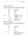
Memory Configuration
The following assembler code segment can be used to
determine the amount of memory available on the card.
eli
mov
mov
out
inc
in
sti
and
returns
al=O
al=20h
where
dX,ATCREG
al,DATA_I
aX,al
dx
al,dx
al,020h
; 256K display memory
installed
; 512k display memory
installed
location is stored in
cOOO:10h
is stored in Obbh
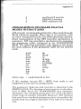
Monitor Configuration
The following assembler code segment can be used to
determine for which monitor the VGAWONDER is currently configured.
eli
mov
mov
out
Inc
In
sti
and
returns al
°
1
2
3
1
dX,ATCREG
dl,DATA_I
dX,al
dx
al,dx
al,Ofh
EGA monitor
PS/2 monochrome monitor
TTL monochrome monitor
PS/2 color monitor
RGB color monitor
56
Appendix B
5
7
d
multiswitch monitor
PS/2 8514 monitor
NEC multisync XL
PROGRAMMING STANDARD EGAlVGA
MODES WITHOUT BIOS
ATI strongly recommends setting the video mode through
BIOS whenever possible. When this is not possible, such
as when writing drivers for non-DOS operating systems,
direct manipulation of the CRT controller parameters is
necessary. ATI has provided a mechanism for accessing
the parameter tables contained in the VGAWONDER
BIOS. The following assembler code segment will locate
the start address of the parameter table for the desired
mode.
push
mov
push
mov
mov
mov
int
mov
pop
pop
ret
bp
bp,sp
es
al,args
ah,12h
bx,5506h
10h
ax,bp
es
bp
where args = mode desired in hex
If this routine returns BP = Oftffh, that mode is not
supported in the current configuration.
The parameter table size and structure is identical to the
IBM EGAlVGA. The function of each register is also identical to IBM. Since the VGA WONDER uses hardware
emulation, the standard parameters are used regardless
of the type of monitor installed. However, ATI cautions
that use of non-standard parameters may not produce the
results that you expect especially if the card is in emulation.
57
Appendix B
SELECTING MEMORY PLANES
Certain ATI enhanced resolution graphics modes employ
a multiple plane memory organization. When one of these
modes is invoked, the video memoryis organized into 64K
planes at aOOOOh to affffh. VGAWONDERS with 256K
memory have 4 planes and those with 512K have 8 planes
available. The following assembler code segment can be
used to select the required plane.
eli
mov
mov
out
inc
in
mov
and
shl
or
mov
dec
out
sti
dx, ATCREG
al,PLANE_SELECT
dx,al
dl
al,dx
ah,al
ah,PLANE_MASK
ch,l
ah,ch
al,PLANE_SELECT
dl
dx,ax
ch = required plane value
PLANE_SELECT = Ob2h
PLANE_MASK = Oe 1h
where
BIOS COMPATIBILITY
As mentioned earlier, the VGAWONDER is 100('yo BIOS
compatible in all standard MDA, CGA, EGA and VGA
modes. The ATI enhanced resolution graphics modes
(modes 54, 61, 62, 63, 65 and 67) do not support many of
the BIOS functions.
The BIOS functions that are not supported are as follows:
Function Description
AH
AH
=
=
1
2
l{emark
Set cursor type
Set cursor position
58
; no cursor
Appendix B
Function Description
Remark
AH= 3
AH= 4
AH= 5
Read cursor position
Read light pen position
Set active display page
AH=
AH=
AH=
AH=
AH=
Scroll page up
Scroll page down
Read character
; no text mode
Write character
Write character at specified
page
Set CGA color palette
Write dot
; use direct I/O to
video memory
Read dot
Write TTY to active page
Character generator
routines
Write string to specified
page
6
7
8
9
A
AH= B
AH= C
AH= D
AH= E
AH= 11
AH= 13
; no light pen port
; only one page
available
All other BIOS routines should be supported including the
mode switching calls and the palette changing calls.
BOOx600 - 16 COLORS (Mode 54h)
Video Memory Organization
The memory organization is identical to 16 color EGA and
VGA modes and consists of256K organized into 4 maps of
64K. One bit from each of the 4 maps is used to compose
each pel. The IBM EGAJVGA Map Mask register is used
to select any or all the maps to be updated.
59
Appendix B
AOOOO:O
~
Reserved
Plane 0
:1.000 I
I Reserved
Plane 1 I
Reserved
Plane 2
I Reserved
Plane 3
J
64K
~
Video Data Format
The video data format is identical to 16 color EGAlVGA
modes. Each pel is represented by a 4 bit word. One bit
from each of the 4 maps are used to compose a pixel. Thus,
each byte of address space contains 8 pels.
LSB**
MSB*
Map 0 '-1_-'------'_-"-_-'-----'-_-'-_-'-----'
Map 1 L-,_-'----'-_-"-_-'----'-_-'-_.L.-.---'
Map
Map
Pel
co
Cl
21
C2
3
C3
L _...L-----'_--L_...L-----'_--L_...L----l
1'-_--'------'_-"-_-'------'_-'-_-'-----'
1
2
3
4
5
* Most Significant Bit
** Least Significant Bit
60
6
7
8
Appendix B
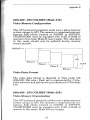
640x400 - 256 COLORS (Mode 61h)
Video Memory Configuration
This ATI enhanced resolution mode uses a plane memory
system unique to AT!. The memory is organized into contiguous 64K blocks located at AOOOOH to AFFFFH.
VGAWONDER must be equipped with 512K of RAM to
operate in this mode. Mode 61 uses 4 pages. The video data
in this mode should only be updated during monitor
retrace periods.
AOOOO:O =>
'<-
JK
Plane 0 I
256, 000
Plane 1 I
Plane 2
I
Plane 3
LJ
Video Data Format
The video data format is identical to VGA mode 13h
(320x200, 256 color). Each pel is represented by 1 byte.
Color selection and palette set up is identical to VGA mode
13h.
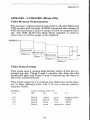
640x480 - 256 COLORS (Mode 62h)
Video Memory Organization
This ATI enhanced resolution modes uses a plane memory
system unique to ATI. The memory is organized into contiguous 64K blocks located at AOOOOH to AFFFFH.
VGAWONDER must be equipped with 512K of RAM to
operate in this mode. Mode 62 uses 5 pages.
61
Appendix B
AOOOO:O=> , - - - - - , ¢ = , - - - - - - - - - - - - - - - - ,
I
Plan e 0
64K
'---------r-----'
D30~,200
, ___-----' I
Plane3
L
Plane 4
Video Data Format
The video data format is identical to VGA mode I3h
(320x200, 256 color). Each pel is represented by 1 byte.
Color selection and palette set up is identical to VGA mode
I3h.
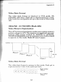
800x600 - 256 COLORS (Mode 63h)
Video Memory Organization
This ATI inhanced resolution mode uses a plane memory
system unique to AT!. The memory is organized into contiguous 64K blocks located at AOOOOH to AFFFFH.
VGAWONDER must be equipped with 5I2K of RAM to
operate in this mode. Mode 63 uses 8 pages.
AOOOO:O =>,------,
¢=¢:::::------------------
Plane 2
62
Appendix B
Video Data Format
The video data format is identical to VGA mode 13h
(320x200, 256 color). Each pel is representecd by 1 byte.
Color selection and palette set up is identical to VGA mode
13h.
1024x768 -16 COLORS (Mode 65h)
Video Memory Organization
This ATI enhanced resolution modes uses a plane memory
system unique to AT!. The memory is organized into contiguous 64K blocks located at AOOOOH to AFFFFH.
VGAWONDER256K must be equipped with 512K of RAM
to operate in this mode. Mode 65 uses 8 pages.
AOOOO:O
=>
'T-
I
64K
Plane 0 I
PI a n e 1 I
Plane 2
'--__- - -' lJ432
Plane 7
Video Data Format
The video data format is unique to this mode. Each pel is
represented by 4 bits with 2 pels per byte.
r---,---,--,----------
.-L----L_ _
63
High Order
PIxel
Low Order
Pixel
Appendix B
1024x768 - 4 COLORS (Mode 67h)
Video Memory Organization
The memory organization is identical to 16 color EGA and
VGA modes and consists of256K organized into 4maps of
64K. One bit from 2 of the 4 maps is used to compose each
pel. The IBM EGAlVGA Map Mask register is used to
select any or all the maps to be updated.
AOOOO:O~
152
Reserved
Plane 0
I I1eserved
I
Pane 1
j
I Reserved
Plane 2
I Reserved
Plane 3
1
64K
~
Video Data Format
This mode uses a unique data format where 2 bits are required per pel. Plane 0 and 1 contain the data for odd
numbered pels and Plane 2 and 3 containing the data of
the even numbered pels.
This mode supports 1 of 4 colors sets. Selection of the color
set is done through bits 4 & 5 of the internal palette
register (3cOh).
3cO Bits
45
00
01
10
11
Color Values (CO, C1)
00
01
10
11
black
black
black
black
bright white
yellow
white
white
white
green
cyan
cyan
64
grey
red
red
magenta
Appendix C
APPENDIXC
65
66
Appendix C
MEMORY UPGRADE
Should you require to upgrade your VGAWONDER to support 512K of video memory, purchase 8 pieces of part #
4464-12, (64Kx4) DRAM chips with an access time of 120
nano seconds or faster from your dealer.
Install the DRAM chips in the empty sockets on the left
hand side of the VGAWONDER board. Care should be
taken to ensure that the key on the chip indicated by a
notch at one end is installed in the same direction as other
chips. After installation, inspect each chip carefully for
bent pins or reverse insertion.
ATI recommend that the installation of these memory
chips be done by a qualified technician.
Warning: DRAM chips are static sensitive devices. The
user must ensure that they have discharged any static
electricity by grounding themselves to the chassis of the PC
before handling the chips.
67
Specifications
VIDEO FEATURE CONNECTOR
13x2 edge connector located at the top of the card, IBM
standard.
VIDEO DISPLAY BUFFER OF VIDEO MEMORY
256Kbytes
(512K bytes optional)
SYNC SIGNALS
Seperate horizontals and vertical sync in TTL levels
Horizontal
31.469kHz - Analog monitor
21.8kHz - EGA monitor
15.75kHz - RGB monitor
18.432kHz - TTL Monochrome monitor
Vertical
70 Hz - Analog monitor
60 Hz - EGA monitor
60 Hz - RGB monitor
50 Hz - TTL Monochrome monitor
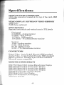
CONNECTORS
Digital Video- 9-pin D shell (Female) IBM standard
Analog Video- 15-pin D shell (Female) IBM standard
Mouse connector- Hosiden 9-pin circular connector
Microsoft mouse compatible
MONITOR COMPATIBLITY
IBM PS/2 Model 8503 Analog Monochrome Display
IBM PS/2 Model 8512 Analog Color Display
IBM PS/2 Model 8513 Analog Color Display
IBM PS/2 Model 8514 Analog Color Display
IBM Model 5151 Monochrome Display
IBM Model 5153 Color Display
IBM 5154 Enhanced Color Display
Multisync monitor
69
Specifications
SIZE
8.5" x 4.2"
POWER
+5V +/- 5%,
@ 1.3
AMP
ENVIRONMENT
Ambient Temperature - 10° to 50° degrees C
(operation)
0° to 70° degrees C (storage)
Relative Humidity - 5% to 90% (operation)
(non-condensing) 0% to 95% (storage)
BUS
IBM PC or AT standard
BUS LOADING
No more than 2 LS TTL load
SYSTEM REQUIREMENTS
IBM PCIXT/AT, PS/2 Model 30 or compatible system.
70
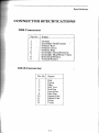
Specifications
CONNECTOR SPECIFICATIONS
DB9 Connector
Pin No.
Signal
1
2
3
4
5
Ground
Secondary Red/Ground
Primary Red
Primary Green
Primary Blue
Secondary Green!Intensity
Secondary Blue/Mono Video
Horizontal Retrace
Vertical Retrace
6
7
8
9
DB15 Connector
Pin No.
1
2
3
5
6
7
8
10
II
13
14
Signal
Red
Green
Blue
Self Test
Red Rtn
Green Rtn
Blue Rtn
Digital Gnd
Digital Gnd
Hsync
Vsync
71
Specifications
Mouse Connector
Pin No.
Signal
1
2
+5V
XA
3
XB
4
YA
5
YB
6
SWI
SW2
SW3
Ground
Chasis Ground
7
8
9
E
VIDEO FEATURE CONNECTOR
2x13 edge connector located at the top of the VGAWonder.
MOUSE PORT
Mouse interrupt rate - 30hz
Mouse port address - 23Ch - 23Fh or 238h - 23Bh software
selectable
Interrupt level
- 2-5 software selectable
72
FCC Compliance Statement
This equipment generates and uses radio frequency energy and, if not properly installed and used correctly, that
is, in strict accordance with the manufacturer's instructions, may cause interference to radio and television
reception. It has been type tested and found to comply with
the limits for a Class B computing device in accordance
with the specifications in Subpart J of Part 15 of FCC
rules, which are designed to provide reasonable protection
against such interference in a residential installation.
However, there is no guarantee that interference will not
occur in a particular installation. If this equipment does
cause interference with radio or television reception,
which can be determined by turning the equipment off and
on, the user is encouraged to try to correct the interference
by one or more of the following measures:
- Reorient the receiving antenna
- Relocate the computer with respect to the receiver.
- Move the computer into a different outlet so that
computer and receiver are on different branch circuits.
If necessary, the user should consult the dealer or an experienced radio/television technician for additional
suggestions. The user may find the following booklet
prepared by the Federal Communications Commission
helpful: "How to Identify and Resolve Radio/TV Interference Problems".This booklet is available from the US
Government Printing Office, Washington, DC 20402.
Stock No. 004-000-00345-4.
VGA Wonder FCC ID: EXM5RSVGAI
Certified to comply with the limits for a Class B computing
device pursuant to Subpart J of Part 15 of FCC rules. See instructions if interference to radio
is suspected.
This user's monitor requires the use of shielded cables for
connection to a computing device. Required to assure compliance with FCC regulations.
73
74
Reference
Title:
EGAlVGA A Programmer's Reference
Guide
Author:
Bradley Dyck Kliewer
Publisher: McGraw Hill
Date:
1988
Title:
Programmer Guide to IBM PC and
PS/2 Video Systems
Author:
Richard Wilton
Publisher: Microsoft Press
Date:
1987
Title:
Personal System/2 and Personal
Computer BIOS Interface Technical
Reference
None
Author:
Publisher: IBM
Date:
April,1988
75
76
Index
Page
3.5" diskettes
- 7
8 bit slot
16 bit databus card
- 4,9,21
-1,4,9,
21
A
Adapter
VGA Video
Color Graphics; (CGA)
Dual
Enhanced Graphic, (EGA)
Hercules Graphics
Monochrome Display, (MDA)
- 1
- 2,5,35
- 10
- 2,13
- 2,35
- 2,5,35
Analog Mode
- 17
AutoCAD
- 3,27
AutoShade
- 3
BIOS
- 3
CGA
-
CMOS VLSI Gate Array Technology
- 3
Compatibles
286/386
IBM PC/AT
IBM PCIXT
IBM Personal System/2
-
B
C
77
2,3,4,
5, 16
1
1
1
1
Index
Page
Connectors
15 pin
9 pin
-18,19,22
- 22
Contents of the Package
- 7
Diagnostics and Troubleshooting
Dual Monitor Installation
- 43
- 37
EGA
-
Features
- 3
GEM
- 3,27
Gold Finger
- 21, 22
Hercules Graphics Card, (HGC)
- 2,3,4,
5, 13, 16
Installation Related Problems
No Display Problems
Error Messages
Operational Problems
- 44
- 44
- 45
- 46
Installing The VGAWONDER
- 21
Interlacing
- 2
Introduction
- 1
D
E
2,4,5,
16
F
G
H
I
78
Index
Page
M
Microprocessors
80186
80286
80386
- 21
- 21
- 21
Monitors
VGNAnalog
Dual
EGA
EGA Color
IBM 8514
IBM PC
IBM PC/AT
IBMPCIXT
IBM Personal
IBM Personal System/2 Model 30
Mul tifrequency
Multisync
RGB
TTL Monochrome
- 2,5,17
- 9,34,37
- 2,4,5,16
- 2
-17
- 4, 12,21
- 4,12,13,
21
- 4, 13,21,
37
-10
- 2,9, 10,
12
- 1,2,4,
10,18,22
- 1,2,4,
5, 19
- 2,4,5,16
- 2,4, 15,
22
Mouse
- 5
Mouse.Com
- 28
Mouse Interface
- 39
Mouse.Sys
- 28
OS/2
- 3
0
79
Index
Page
Q
R
Quick Start
- 25
Reassembling The PC
- 23
Resolutions
1024x768
640x480
720x350
752x410
800x600
960x720
EGA
-
Service Department
- 49
Setting Up Your Computer
-11
Software Installation
- 27
Supported Software
Lotus 1-2-3
NewViews
Smarterm
Vterm
WordPerfect
WordStar
-
Switch Selections
- 37
Switch Settings
- 13
System Requirements
- 9
VCONFIG
- 29
1,2, 17
2
2,17
2
2,17
2,17
2
S
4
4
4
4
4
4
V
80
Index
Page
VCONFIG Options
132x25
132x44
132x60
CGA
EGA
Exit
MDA Mono Graphics 640x480
MDA Mono Graphics 720x348
Screen Save
- 31
- 31
- 31
- 31
- 31
- 32
- 31
- 31
- 32
Ventura
- 3
VGATEST
- 23, 43
Video Memory
- 3
VINSTALL
- 29
VSETUP
- 33
VSETUP Options
Analog Monitor Selection
CGA
Dual Monitor
EGA (and dual monitor
configurations)
Exit and Save Configuration
MDA Mono Graphics 720x348
MDA Mono Graphics 640x400
Mouse Option Select
Primary Card
Secondary Card
VGA
- 34
- 36
- 35
- 36
- 36
- 34
- 35
- 34
Warranty
Windows
-79
- 3,27
- 34
- 35
- 34
W
81
82