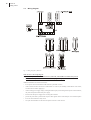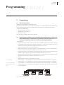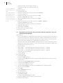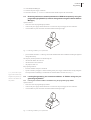
1
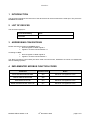
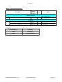
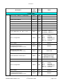
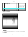
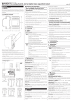
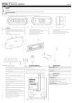
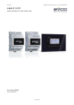
EVD120
Summary
Summary
[ EVD120 ]
Important
Important ............................................................................................................................................................. 5
Introduction
Introduction ......................................................................................................................................................... 7
Getting started
1
Getting started ..................................................................................................................................................... 9
1.1
Installing the instrument ..................................................................................................................................... 9
1.2
Wiring diagram ................................................................................................................................................. 10
Programming
2
Programming ..................................................................................................................................................... 11
2.1
Preliminary remarks .......................................................................................................................................... 11
2.2
Programming an EVD120 having standard network parameters using the software RICS
(adding an EVD120 having standard network parameters to an existing and working network of
instruments managed by RICS) ........................................................................................................................ 11
2.3
Programming an EVD120 having standard network parameters using the software Params Manager .......... 12
2.4
Restoring well-known network parameters of EVD120 temporarily using the programming key
EVKEY (in order to change them using the software Params Manager) ......................................................... 13
2.5
Learning/Programming the instrument address of EVD120 using the programming key EVKEY ................ 13
2.5.1
Learning the instrument address of EVD120 using the programming key EVKEY ....................................... 13
2.5.2
Programming the instrument address of EVD120 using the programming key EVKEY ................................ 15
2.6
Copying the configuration parameters of EVD120 in the programming key EVKEY using the software
Params Manager ................................................................................................................................................ 16
2.6.1
Copying the configuration parameters of EVD120 in the programming key EVKEY using the software
Params Manager (in order to program several EVD120 that are different of the instrument address) ........... 16
2.7
Reading the configuration parameters of EVD120 from the programming key EVKEY ............................... 17
Configuration parameters
3
Configuration parameters ................................................................................................................................. 19
3.1
Preliminary remarks .......................................................................................................................................... 19
3.2
Configuration parameters ................................................................................................................................. 19
Signals
4
Signals ............................................................................................................................................................... 23
4.1
LED Power/Status ............................................................................................................................................. 23
4.2
LED Communication (on port 1) ...................................................................................................................... 23
4.3
LED Prog ........................................................................................................................................................... 24
Technical data
5
Technical data ................................................................................................................................................... 25
5.1
Technical data ................................................................................................................................................... 25
3
EVD120
Important
[ EVD120 ]
Important
Important
Read these instructions carefully before installing and using the instrument and follow all additional information for
installation and electrical connection; keep these instructions close to the instrument for future consultations.
The instrument must be disposed according to the local legislation about the collection for electrical and electronic
equipment.
5
EVD120
Introduction
[ EVD120 ]
Introduction
Introduction
EVD120 is a two analog channels and two digital inputs acquisition module.
Each analog channel can work with one of the following kind of probe (universal analog channels):
•
PTC/NTC probe
•
J/K thermocouple
•
2/3 wires Pt 100 and Pt 1000 probe
•
2/3 wires 4-20 mA passive current transducer
•
0-10/2-10 V and 0-20/4-20 mA active transducer.
The instrument has the following communication ports:
•
RS-485 port with MODBUS communication protocol, to allow the connection of the instrument in RS-485 networks with MODBUS communication protocol
•
serial port for the communication with the programming key EVKEY.
The case of EVD120 is 3 DIN modules.
7
EVD120
Getting started
[ EVD120 ]
Getting started
1
Getting started
1.1
Installing the instrument
On DIN rail; dimensions in mm (in).
Fig. 1 - Dimensions of EVD120.
Fig. 2 - Installation of EVD120.
Additional information for installation:
•
working conditions (working temperature, humidity, etc.) must be between the limits related in the technical data
•
do not install the instrument close to heating sources (heaters, hot air ducts, etc.), devices provided with big magne-
•
according to the safety legislation, the protection against electrical parts must be ensured by a correct installation of
tos (big speakers, etc.), locations subject to direct sunlight, rain, humidity, dust, mechanical vibrations or bumps
the instrument; the parts that ensure the protection must be installed so that you can not remove them if not by using
a tool.
9
10
EVD120
Getting started
1.2
Wiring diagram
Fig. 3 - Wiring diagram of EVD120.
With reference to the wiring diagram:
•
port 1 is the port for the serial communication (via RS-485, with MODBUS communication protocol)
•
port 2 is the serial port for the communication with the programming key.
Additional information for electrical connection:
•
do not operate on the terminal blocks with electrical or pneumatic screwers
•
if the instrument has been moved from a cold location to a warm one, the humidity could condense on the inside;
wait about an hour before supplying it
•
test the working power supply voltage, working electrical frequency and working electrical power of the instrument;
they must correspond with the local power supply
•
disconnect the local power supply before servicing the instrument
•
provide the probes with a protection able to protect them against contacts with metal parts or use insulated probes
•
do not use the instrument as safety device
•
for repairs and information on the instrument please contact Evco sales network.
EVD120
Programming
[ EVD120 ]
Programming
2
Programming
2.1
Preliminary remarks
EVD120 supports the MODBUS communication protocol.
The kind of network EVD120 can work in is RS-485 (look at Fig. 4); for further information on the realization of the
network, consult the Installation manual of RICS for Windows® (the document is available in the CD of RICS).
According to the standard settings:
•
the instrument address has value 247
•
the baud rate has value 9,600 baud
•
the parity has value even.
These parameters are hereinafter called “network parameters”.
2.2
Programming an EVD120 having standard network parameters using the software RICS (adding an EVD120 having standard network parameters to an
existing and working network of instruments managed by RICS)
Operate as follows:
•
make sure the network is made of instruments that support the MODBUS communication protocol; to learn the
communication protocol supported by the instruments, consult the List of compatible instruments and supported
communication protocol (the document is available in the internet site www.evco.it)
•
make sure the network is made of less than 32 instruments
•
make sure no instrument in the network has value 247 as instrument address; to learn the instrument address,
consult the instructions (the document is available in the internet site www.evco.it)
•
make sure the baud rate of the instruments in the network has value 9,600 baud; to learn the baud rate of the
instrument, consult the instructions (the document is available in the internet site www.evco.it)
•
make sure the parity of the instruments in the network has value even; to learn the parity of the instrument, consult
the instructions (the document is available in the internet site www.evco.it)
•
quit RICS
•
disconnect the power supply of the instruments in the network
•
connect terminal “ + ” of the hardware driver of the last instrument in the network to terminal “ 1 ” of EVD120 (1)
•
connect terminal “ -- ” of the hardware driver of the last instrument in the network to terminal “ 2 ” of EVD120 (1)
pair, as far as possible, the ca-
•
connect terminal “ S ” of the hardware driver of the last instrument in the network to terminal “ 3 ” of EVD120 (2)
ble to the ones you have already con-
•
to reduce the reflections on the signal transmitted through the cable, plug in the termination of the first and last
(1)
(2)
use a twisted pair
nected
element of the network
Fig. 4 - Example of RS-485 network.
11
12
EVD120
Programming
(3)
gain access to RICS with the
•
operate the remaining connections related in paragraph 1.2
•
connect the power supply of the instruments in the network
•
start RICS (3) (4) .
account of the administrator or of the
Keep operating as follows:
installer
1.
Quit possible dialog boxes.
(4)
2.
Right-click on the desktop, then use the quick menu to choose Add Device.
the availability of the functions
A new picture will be shown.
of EVD120 depends on the RICS
version; consult the List of compat-
3.
Right-click on the picture, then use the quick menu to choose Setup.
The dialog box Setup Device will be shown.
ible instruments and supported communication protocol (the document
4.
Click the card Network, then digit 247 in the pop-up menu Address.
is available in the internet site
5.
Choose OK.
www.evco.it)
6.
Right-click on the picture, then use the quick menu to choose Examine > Parameters.
The dialog box Parameters will be shown.
7.
Change the configuration parameters according to your requirements.
8.
Change the instrument address.
9.
Quit the dialog box Parameters.
10. Switch off/on the power supply of EVD120.
11. Repeat steps 3, 4 and 5.
2.3
Programming an EVD120 having standard network parameters using the
software Params Manager
Operate as follows:
•
make sure Params Manager is installed in the Personal Computer and the connection between the serial interface
and the Personal Computer works; for further information on the installation of Params Manager and on the realization of the connection between the serial interface and the Personal Computer, consult the User manual of Params
Manager (the document is available in the CD of RICS and in the internet site www.evco.it)
•
make sure the serial interface supports the MODBUS communication protocol; to learn the communication protocol
supported by the serial interfaces, consult the User manual of Params Manager (the document is available in the
CD of RICS and in the internet site www.evco.it)
•
quit Params Manager
•
connect terminal “ + ” of the RS-485 output of the serial interface to terminal “ 1 ” of EVD120
•
connect terminal “ -- ” of the RS-485 output of the serial interface to terminal “ 2 ” of EVD120
•
connect terminal “ S ” of the RS-485 output of the serial interface to terminal “ 3 ” of EVD120
•
switch on the power supply of EVD120
•
start Params Manager.
Keep operating as follows:
1.
Choose Program setup.
The dialog box Setup will be shown.
2.
Use the pop-up menu COM port to choose the COM number of the Personal Computer where you have connected
3.
Use the pop-up menu External HW/Protocol to choose DIRECT.
the serial interface.
4.
Use the pop-up menu Baud rate to choose 9600.
5.
Use the pop-up menu Parity to choose Even.
6.
Click the card Device Settings, then use the pop-up menu Protocol to choose MODBUS (DIRECT).
7.
Digit 247 in the text field Address.
8.
Choose Apply.
The frame Information will be shown.
9.
Choose OK, then Exit.
10. Start Params Manager again.
11. Choose Link source device.
The dialog box Source device map will be shown.
12. Change the configuration parameters according to your requirements.
13. Change the instrument address.
EVD120
Programming
14. Choose Exit, then Exit again.
15. Switch off the power supply of EVD120.
16. Disconnect terminals “1”, “2” and “3” of EVD120 from the RS-485 output of the serial interface.
2.4
Restoring well-known network parameters of EVD120 temporarily using the
programming key EVKEY (in order to change them using the software Params
Manager)
Operate as follows:
•
make sure to have the programming key EVKEY
•
switch on the power supply of EVD120 and wait 4 s at least since the power supply has been switched on
•
connect EVKEY to port 2 of EVD120: the LED of EVKEY will shed green light
Fig. 5 - Connecting EVKEY to port 2 of EVD120.
•
press the button of EVKEY 1 s: LED Prog of EVD120 will flash and the LED of EVKEY will shed green light and
red light alternatively.
The temporary network parameters are the following ones:
•
the instrument address has value 248
•
the baud rate has value 9,600 baud
•
the parity has value even.
Keep operating as follows:
(5)
•
disconnect EVKEY from port 2 of EVD120
•
operate as related in paragraph 2.3 without switching off the power supply of EVD120 before having changed its
network parameters and holding in consideration the instrument address has value 248 (step 7.) (5) .
if you switch off the power
supply of EVD120 before having
changed its network parameters, you
2.5
Learning/Programming the instrument address of EVD120 using the programming key EVKEY
2.5.1
Learning the instrument address of EVD120 using the programming key EVKEY
will restore its not well-known network parameters
Operate as follows:
•
make sure to have the programming key EVKEY
•
switch on the power supply of EVD120 and wait 4 s at least since the power supply has been switched on
•
connect EVKEY to port 2 of EVD120: the LED of EVKEY will shed green light
Fig. 5 - Connecting EVKEY to port 2 of EVD120.
13
14
EVD120
Programming
•
press the button of EVKEY 1 s: LED Prog of EVD120 will flash and the LED of EVKEY will shed green light and
•
press and release the button of EVKEY: the LED of EVD120 will go out; if the LED of EVKEY sheds green light
red light alternatively
(6)
consider value 0, if it sheds red light consider value 1 (6)
the value to consider is not the
instrument address; the instrument
address is the sum of all the values
to consider in the procedure
•
press and release the button of EVKEY: LED Prog of EVD120 will light up; if the LED of EVKEY sheds green light
consider value 0, if it sheds red light consider value 2 (6)
•
press and release the button of EVKEY: LED Communication of EVD120 will light up; if the LED of EVKEY sheds
green light consider value 0, if it sheds red light consider value 4 (6)
•
press and release the button of EVKEY: LED Communication and LED Prog of EVD120 will light up; if the LED of
EVKEY sheds green light consider value 0, if it sheds red light consider value 8 (6)
•
press and release the button of EVKEY: LED Power/Status of EVD120 will light up; if the LED of EVKEY sheds
green light consider value 0, if it sheds red light consider value 16 (6)
•
press and release the button of EVKEY: LED Power/Status and LED Prog of EVD120 will light up; if the LED of
EVKEY sheds green light consider value 0, if it sheds red light consider value 32 (6)
EVD120
Programming
•
press and release the button of EVKEY: LED Power/Status and LED Communication of EVD120 will light up; if
the LED of EVKEY sheds green light consider value 0, if it sheds red light consider value 64 (6)
•
press and release the button of EVKEY: all the LED of EVD120 will light up; if the LED of EVKEY sheds green
light consider value 0, if it sheds red light consider value 128 (6)
•
press and release the button of EVKEY: the procedure will be quitted, LED Prog of EVD120 will flash and the LED
•
disconnect EVKEY from port 2 of EVD120
•
switch off/on the power supply of EVD120
•
the instrument address is the sum of all the values to consider in the procedure.
of EVKEY will shed green light
To quit the procedure early operate as follows:
•
disconnect EVKEY from port 2 of EVD120
•
switch off/on the power supply of EVD120.
2.5.2
Programming the instrument address of EVD120 using the programming key EVKEY
Operate as follows:
(7)
•
operate as related in paragraph 2.5.1
•
to the steps “if the LED of EVKEY sheds green light consider value ... , if it sheds red light consider value ... ”, press
the button of EVKEY 4 s: the LED of EVKEY will change colour (7)
do not assign the instrument
address the following values: 0, 248,
To continue the procedure operate as follows:
249, 250, 251, 252, 253, 254 or 255;
•
if you assign the values 0 or 255,
To save the modification operate as follows:
LED Power/Status of EVD120 will
•
after the step “if the LED of EVKEY sheds green light consider value 0, if it sheds red light consider value 128”,
•
press the button of EVKEY 4 s: the procedure will be quitted, LED Prog of EVD120 will flash and the LED of
press and release the button of EVKEY: all the LED of EVD120 will flash
flash and the LED of EVKEY will
shed red light
(8)
press and release the button of EVKEY.
EVKEY will shed green light (8)
if you press and release the
button of EVKEY, the procedure will
•
disconnect EVKEY from port 2 of EVD120
be quitted without saving the modi-
•
switch off/on the power supply of EVD120.
fication
To quit the procedure early operate as follows:
•
disconnect EVKEY from port 2 of EVD120
•
switch off/on the power supply of EVD120.
15
16
EVD120
Programming
2.6
Copying the configuration parameters of EVD120 in the programming key
EVKEY using the software Params Manager
Operate as follows:
•
make sure to have the programming key EVKEY
•
switch on the power supply of EVD120 and wait 4 s at least since the power supply has been switched on
•
connect EVKEY to port 2 of EVD120: the LED of EVKEY will shed green light
Fig. 5 - Connecting EVKEY to port 2 of EVD120.
•
press the button of EVKEY 1 s: LED Prog of EVD120 will flash and the LED of EVKEY will shed green light and
red light alternatively.
•
operate as related in paragraph 2.3 till step 12 inclusive holding in consideration the instrument address has value
248 (step 7.).
Keep operating as follows:
1.
Choose Store to key.
The configuration parameters of EVD120 will be copied in EVKEY; during the copy the LED of EVKEY sheds red
light.
the copy of the configuration
2.
Wait the LED of EVKEY finishes shedding red light (9) .
parameters takes 10 s at most; if in
3.
Choose Exit, then Exit again.
this time EVKEY does not signal the
4.
Switch off the power supply of EVD120.
operation has successfully been com-
5.
Disconnect EVKEY from port 2 of EVD120.
pleted (or the LED of EVKEY fin-
6.
Disconnect terminals “1”, “2” and “3” of EVD120 from the RS-485 output of the serial interface.
(9)
ishes shedding red light to shed green
light again), it takes to switch off the
2.6.1
ment address)
nect EVKEY from port 2 of EVD120
and repeat the copy
Copying the configuration parameters of EVD120 in the programming key EVKEY using the
software Params Manager (in order to program several EVD120 that are different of the instru-
power supply of EVD120, discon-
Operate as follows:
•
operate as related in paragraph 2.6 making sure parameter Enable AutoIncremental Address Key has value 1.
The first EVD120 programmed with the procedure related in paragraph 2.7 will have the same configuration
parameters of the EVD120 used to copy the configuration parameters in EVKEY; the second EVD120 programmed with the procedure related in paragraph 2.7 will have the same configuration parameters of the EVD120
used to copy the configuration parameters in EVKEY but parameter instrument address (its value will be increased of one unit); the third EVD120 programmed with the procedure related in paragraph 2.7 will have the
same configuration parameters of the EVD120 used to copy the configuration parameters in EVKEY but parameter instrument address (its value will be increased of two units) and so on.
EVD120
Programming
2.7
Reading the configuration parameters of EVD120 from the programming key
EVKEY
Operate as follows:
•
make sure to have the programming key EVKEY
•
switch off the power supply of EVD120
•
connect EVKEY to port 2 of EVD120
•
switch on the power supply of EVD120 and wait 4 s at least since the power supply has been switched on: LED Prog
•
press the button of EVKEY 4 s: the configuration parameters of EVKEY will be copied in EVD120; during the copy
of EVD120 will flash and the LED of EVKEY will shed green light
the LED of EVKEY sheds red light (10)
(10) the copy of the configuration
parameters in EVD120 is only al-
•
wait the LED of EVKEY finishes shedding red light (9)
lowed if the firmwares of the instru-
•
switch off the power supply of EVD120
ments coincide; if they do not coin-
•
disconnect EVKEY from port 2 of EVD120.
cide, LED Power/Status and Prog of
EVD120 will flash and the LED of
EVKEY will shed red light.
17
EVD120
Configuration parameters
[ EVD120 ]
Configuration parameters
3
Configuration parameters
3.1
Preliminary remarks
Configuration parameters are visible using one of the following software:
•
RICS
•
Params Manager.
3.2
(11) if parameters “Probe kind 1”
Configuration parameters
TEXT FIELD
MIN.
MAX. U.M.
DEF.
ANALOG CHANNELS
Celsius Fahrenheit
0
1
0
unit of measure temperature (11)
---
and/or “Probe kind 2” have value 8,
0
=
°C
9, 10 or 11, parameter “Celsius Fahr-
1
=
°F
enheit” will have no effect
Enable Probe 1
0
1
---
1
enabling the analog channel 1
1
Enable Probe 2
0
1
---
1
Probe kind 1
0
14
---
1
YES
enabling the analog channel 2
1
(12) switch off/on the power sup-
=
=
YES
kind of probe analog channel 1 (12)
ply of the instrument after the modi-
0
=
PTC
fication of the parameter
1
=
NTC
2
=
J
3
=
K
4
=
reserved
5
=
3 wires Pt 100
6
=
2 wires Pt 100
7
=
reserved
8
=
reserved
9
Probe kind 2
0
14
---
1
=
3 wires Pt 1000
10 =
2 wires Pt 1000
11 =
4-20 mA
12 =
0-20 mA
13 =
2-10 V
14 =
0-10 V
kind of probe analog channel 2 (12)
0
=
PTC
1
=
NTC
2
=
J
3
=
K
4
=
reserved
5
=
3 wires Pt 100
6
=
2 wires Pt 100
7
=
reserved
8
=
reserved
9
=
3 wires Pt 1000
19
20
EVD120
Configuration parameters
10 =
2 wires Pt 1000
11 =
4-20 mA
12 =
0-20 mA
13 =
2-10 V
14 =
0-10 V
(13) the unit of measure depends on
Probe1 Offset
-25.0
25.0
(13)
0.0
offset analog channel 1
parameters “Celsius Fahrenheit” (°C
Probe2 Offset
-25.0
25.0
(13)
0.0
offset analog channel 2
or °F) and “Probe kind 1” or “Probe
DigitalFilter probe 1
0
6
---
3
reading speed analog channel 1 (0 = fast ... 6 = slow) (12)
kind 2” (temperature or variable of
DigitalFilter probe 2
0
6
---
3
reading speed analog channel 2 (0 = fast ... 6 = slow) (12)
the range of the transducer).
MinTarI 1
-1500.0 1500.0 points
0.0
minimum value of the range of the transducer of the analog channel 1 corresponding to 0/4 mA or 0/2 V
MinTarI 2
-1500.0 1500.0 points
0.0
minimum value of the range of the transducer of the analog channel 2 corresponding to 0/4 mA or 0/2 V
MaxTarI 1
-1500.0 1500.0 points
100.0
maximum value of the range of the transducer of the analog channel 1 corresponding to 20 mA or 10 V
MaxTarI 2
-1500.0 1500.0 points
100.0
maximum value of the range of the transducer of the analog channel 2 corresponding to 20 mA or 10 V
Saturation
0
3
---
0
Configuration 1
Saturation
values the signal of the transducer of the analog channel 1
saturates (or finishes being converted by the instrument)
0
3
---
0
Configuration 2
0
=
function not enabled
1
=
below “MinTarI 1” and above “MaxTarI 1”
2
=
below 0.0 and above 100.0
3
=
below 0.0 and above 1000.0
values the signal of the transducer of the analog channel 2
saturates (or finishes being converted by the instrument)
0
=
function not enabled
1
=
below “MinTarI 2” and above “MaxTarI 2”
2
=
below 0.0 and above 100.0
3
=
below 0.0 and above 1000.0
TEXT FIELD
MIN.
MAX. U.M.
DEF.
DIGITAL INPUTS
Polarity Digital Input 1
0
1
0
kind of contact digital input 1
Polarity Digital Input 2
0
1
---
---
0
0
=
NO (input active if you close the contact)
1
=
NC (input active if you open the contact)
kind of contact digital input 2
0
=
NO (input active if you close the contact)
1
=
NC (input active if you open the contact)
TEXT FIELD
MIN.
MAX. U.M.
DEF.
SERIAL COMMUNICATION (MODBUS)
Address
1
247
---
247
instrument address
Baud rate
0
3
---
2
baud rate
Parity
0
2
---
2
(12)
(12)
0
=
2,400 baud
1
=
4,800 baud
2
=
9,600 baud
3
=
parity
19,200 baud
(12)
0
=
none
1
=
odd
2
=
even
EVD120
Configuration parameters
TEXT FIELD
MIN.
MAX. U.M.
DEF.
Enable AutoIncremental
0
1
1
Address Key
---
PROGRAMMING
enabling the function of automatic increase (of one unit)
of the instrument address (parameter “Address”) during
the copy of the parameter set from the programming key
to the instrument
21
EVD120
Signals
[ EVD120 ]
Signals
4
Signals
4.1
LED Power/Status
If it is lit, the instrument will be supplied.
If it flashes, an analog channel 1 error and/or an analog channel 2 error will be running.
Remedies:
•
look at parameters “Probe kind 1” and/or “Probe kind 2”
•
check the integrity of the probe
•
check the connection instrument-probe
•
check the variable read by the probe.
If it is out, the instrument will not be supplied.
4.2
LED Communication (on port 1)
If it is mainly lit, the serial communication will correctly be running.
23
24
EVD120
Signals
If it flashes, the instrument will read some data but it will not be the recipient.
Remedies:
•
look at parameters “instrument address” of the instruments of the RS-485 network.
If it is mainly out, the instrument will read some not correct data.
Remedies:
•
look at parameters “baud rate” and “parity” of the instruments of the RS-485 network.
If it is out, the serial communication will not be running.
4.3
LED Prog
If it is lit or if it flashes, the programming of the instrument will be running.
EVD120
Technical data
[ EVD120 ]
Technical data
5
Technical data
5.1
Technical data
Box:
self-extinguishing grey.
Frontal protection:
IP 40.
Connections:
•
screw terminal blocks (power supply, inputs and port for the serial communication)
•
6 poles connector (port for the communication with the programming key).
Working temperature:
from 0 to 55 °C (32 to 131 °F, 10 ... 90% of relative humidity without condensate).
Power supply:
230 VAC, 50/60 Hz, 1.5 VA (approximate).
Analog channels:
2 (analog channel 1 and analog channel 2) for:
•
PTC/NTC probes
•
J/K thermocouples
•
2/3 wires Pt 100 and Pt 1000 probes
•
2/3 wires 4-20 mA passive current transducers
•
0-10/2-10 V and 0-20/4-20 mA active transducers
(universal analog channels).
Digital inputs:
2 (digital input 1 and digital input 2) for NO/NC contact (free of voltage, 12 V 5 mA approximate).
Working range:
•
from -50 to 150 °C (-50 to 300 °F) for PTC probe
•
from -40 to 110 °C (-40 to 230 °F) for NTC probe
•
from -100 to 800 °C (-140 to 1,450 °F) for J thermocouple
•
from -100 to 1,300 °C (-140 to 2,350 °F) for K thermocouple
•
from -100 to 650 °C (-140 to 1,200 °F) for 2/3 wires Pt 100 probe
•
from -100 to 650 °C (-140 to 1,200 °F) for 2/3 wires Pt 1000 probe.
Resolution:
•
0.1 for 2/3 wires 4-20 mA passive current transducers and for 0-10/2-10 V and 0-20/4-20 mA active transducers
•
0.1 °C/1 °F otherwise.
Serial ports:
•
port for the serial communication (via RS-485, with MODBUS communication protocol)
•
port for the communication with the programming key.
25
User manual of EVD120.
Version 1.00 of November 2006.
File EVD120_user_manual_eng_v1.00.pdf.
PT.
This document belongs to Evco; unless you are authorized by Evco, you can not publish it. Evco does not take any responsibility about features, technical data and possible mistakes related in this document
or coming by its use. Evco does not take any responsibility about damages coming by the non-observance of the additional information. Evco reserves the right to make any change without prior notice and
at any time without prejudice the basic safety and operating features.
MODBUS/JBUS IMPLEMENTATION TABLE
Applied to the following products:
EVD120
File name:
ModBUS_PRJ314AA06_v1.02.pdf
Version:
1.02
Date of release:
12 December 2006
h
Evco S.r.l.
1 INTRODUCTION
This document describes the resources of the device that can be accessed via the serial port. The protocol is
MODBUS RTU/JBUS.
2 LIST OF DEVICES
This document applys to :
Device Name/Family
Notes
EVD120M7
3 ADDRESSING CONVENTIONS
Please note that according to MODBUS specs:
the first register is called register 1
register x must be read ad address x-1
According to JBUS:
the first register is called register 0
register x must be read ad address x
The JBUS convention (zero based) has been used in this document, addresses are shown in hexadecimal
with the leading symbol $.
4 IMPLEMENTED MODBUS FUNCTION CODES
Command
Function Code
Notes
READ HOLDING REGISTERS
$03
Maximum 30 registers at once
WRITE SINGLE REGISTER
$06
WRITE MULTIPLE HR
$10
Maximum 30 registers at once
READ AND WRITE MULTIPLE HR
$17
Maximum 30 registers at once
ModBUS PRJ314AA06 v1.02
th
12 December 2006
page 2 of 8
Evco S.r.l.
Holding register addresses table:
Address
(zero
based)
Description
Access
Notes
DIGITAL INPUTS
Digital inputs register
$0101
R
Bit0 = Digital input 1
Bit1= Digital input 2
PROBES
Probe 1 (1)
$0201
R
1 decimal digit
Probe 2 (1)
$0202
R
1 decimal digit
(1) Probes
Reserved Value
Meaning
$8000
Probe failure
$8001
Data not available
ModBUS PRJ314AA06 v1.02
th
12 December 2006
page 3 of 8
Evco S.r.l.
Address
(zero
based)
Description
Access
Notes
PARAMETERS
Meas. unit (0 = Celsius, 1 = Fahrenheit)
$0601
R/W
Modbus nodes address
$0610
R/W
Baud Rate
$0611
R/W
Parity
$0612
R/W
Enable Auto-incremental address
$0613
R/W
Kind of digital input 1 (0 = NO, 1 = NC)
$061F
R/W
msk $0001 = digital In 1
msk $0002 = digital In 2
bit0
bit1..3
bit4..7
bit8..11
bit12..15
= Enable
= reserved
= Digital filter (2)
= probe kind (3)
= reserved
Probe 1 configuration
$0620
R/W
Probe 1 offset
$0621
R/W
Default 0
Min range of linear input 1
(corresponding to 0/4 mA or 0/2 V)
$0622
R/W
Default 0
Max range of linear input 1
(corresponding to 20 mA or 10 V)
$0623
R/W
Defailt 1000
R/W
0 = no saturation
1 = saturation on min and max
range of linear input 1
2 = saturation on 0, 1000
3 = saturation on 0, 10000
bit0
bit1..3
bit4..7
bit8..11
bit12..15
Kind of saturation of linear input 1
$0624
= Enable
= reserved
= Digital filter (2)
= probe kind (3)
= reserved
Probe 2 configuration
$0630
R/W
Probe 2 offset
$0631
R/W
Default 0
Min range of linear input 2
(corresponding to 0/4 mA or 0/2 V)
$0632
R/W
Default 0
ModBUS PRJ314AA06 v1.02
th
12 December 2006
page 4 of 8
Evco S.r.l.
Max range of linear input 2
(corresponding to 20 mA or 10 V)
$0633
R/W
Default 1000
$0634
R/W
0 = no saturation
1 = saturation on min and max
range of linear input 2
2 = saturation on 0, 1000
3 = saturation on 0, 10000
Firmware ID
$FF08
R
Firmware Variation/revision
$FF09
R
Kind of saturation of linear input 2
INFO
(2) Digital filter: 3 is the default value.
(3) Probe kind
Value
Meaning
0
PTC
1
NTC
2
TC J
3
TC K
4
Reserved
5
Pt 100 3 wires
6
Pt 100 2 wires
7
Rerserved
8
Rerserved
9
Pt 1000 3 wires
10
Pt 1000 3 wires
11
4-20 mA
12
0-20 mA
13
2-10 V
14
0-10 V
PAY ATTENTION:
ALL THE ADDRESSES NOT MENTIONED EXPRESSLY IN THIS DOCUMENT MUST BE CONSIDERED
RESERVED. IF YOU DO NOT RESPECT THIS CONDITION, YOU COULD ALTER THE OPERATION OF
THE INSTRUMENT.
ModBUS PRJ314AA06 v1.02
th
12 December 2006
page 5 of 8
Evco S.r.l.
ULTERIORI HOLDING REGISTER PER USO INTERNO
FOTOGRAFIA SULLO STATO DELLO STRUMENTO:
Tramite questi Holding Register è possibile eseguire una fotografia statica sul funzionamento dello
strumento; in tale fotografia vengono riportati i valori misurati dalle sonde, il minimo e il massimo assunto da
entrambe dal momento del precedente rinfresco, all’attuale lettura, lo stato degli ingressi digitali e degli
allarmi, la traccia di una loro eventuale attivazione o disattivazione precedente.
E’ possibile inoltre monitorare una eventuale informazione aggiuntiva da rilevare, tramite il cosiddetto
“variation register”: tale holding register contiene una serie di flag che vengono alzati nel momento in cuivi è
una qualunque variazione sul funzionamento dello strumento (per esempio se i parametri non vengono mai
modificato non ha senso perdere tempo a monitorarli tutti: è più comodo leggere di continuo un flag che
monitorizza una loro possibile modifica).
Description
Address
(zero
based)
Notes
Access
PARAMETERS
Kind of list
$0500
R
Variation register 1
$0501
R/W
Other flags
$0502
R/W
Current probe 1 value
$0503
R
Current probe 2 value
$0504
R
Probe 1 value memory
$0505
R
Probe 2 value memory
$0506
R
Min probe 1 value
$0507
R
Max probe 1 value
$0508
R
Min probe 2 value
$0509
R
Max probe 2 value
$050A
R
Current digital inputs
$050B
R
Digital inputs memory
$050C
R
Digital input memory min
max
$050D
R
Current status of alarm
$050E
R
ModBUS PRJ314AA06 v1.02
th
(*) Reading this holding register,
memory will be update.
msk $0001: current digital input 1
msk $0002: current digital input 2
msk $0001: digital input 1
msk $0002: digital input 2
msk $0001: memo digital input 1 max
msk $0002: memo digital input 2 max
msk $0100: memo digital input 1 min
msk $0200: memo digital input 2 min
msk $0001: current probe failure 1
msk $0002: current probe failure 2
msk $0004: current calibration error
12 December 2006
page 6 of 8
Evco S.r.l.
Alarm memory
$050F
R
Alarm memory min max
$0510
R
Periodical request
counter init
$0511
R/W
Cold junction current
value (in °C)
$0512
R
UNUSED 1
$0513
R
UNUSED 2
$0514
R
UNUSED 3
$0515
R
Photo counter
$0516
R
Refresh counter
$0517
R
UNUSED 4
$0518
R
UNUSED 5
$0519
R
UNUSED 6
$051A
R
UNUSED 7
$051B
R
UNUSED 8
$051C
R
Periodical request
counter
$051D
R/W
Refresh status memory
command
$0480
W
msk $0001: probe failure 1
msk $0002: probe failure 2
msk $0004: calibration error
msk $0001: probe failure 1 max
msk $0002: probe failure 2 max
msk $0004: calibration error max
msk $0100: probe failure 1 max
msk $0200: probe failure 2 max
msk $0400: calibration error max
Time for periodical request counter;
this value will be adjust with a random
time between 0 and 7.
when this counter become null,
instrument’s status memory will be
updated. Reading this holding
register, memory will be update.
Counter for periodical request; when
this counter become null, bit 4 in the
variation register become 1.
write 1 to refresh status memory;
writing 1, status memory will be
updated.
(*)
bit15
bit14
bit13
bit12
bit11
bit10
bit9
bit8
bit7
bit6
bit5
bit4
bit3
bit2
bit1
bit0
bit0, bit1: allways 0;
bit2, bit3: reserved;
bit4: periodical request by timer;
bit5: some variation occurred;
bit6: reset occurred;
bit7: internal status changed
bit8: alarm status changed
ModBUS PRJ314AA06 v1.02
th
12 December 2006
page 7 of 8
Evco S.r.l.
bit9: analogical input changed
bit10: digital input changed
bit11: analogical output changed
bit12: digital input changed
bit13: parameters value changed
bit14:set point or other internal settings changed
bit 15: reserved
ModBUS PRJ314AA06 v1.02
th
12 December 2006
page 8 of 8