1
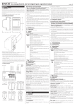
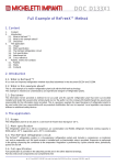
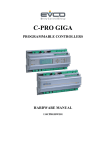
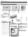
Evco S.p.A. • Code 104QKB33000A01 • page 1/2
SMALL K
Cold room controllers
version 1.01
GB
1
1.1
ENGLISH
IMPORTANT
Important
Read these instructions carefully before installing and using the device and follow all additional information for installation and electrical connection; keep these instructions close to the device for future
consultations.
The device must be disposed according to the local legislation about the collection for electrical and electronic equipment.
2
SIZE AND INSTALLATION
2.1
Size
Size in mm (in).
The drawing on the left shows the version with switches; the drawing in the middle shows the version without switches.
2.2
Installation
With reference to the following drawing, the device is made of:
a)
1 preassembled (instrument, fixing brackets of the instrument, polyester and switches, these last if foreseen) frontal
covering
b)
1 back covering
c)
2 screw hider plugs assembling the coverings
To install the device operate as follows:
1.
Make two holes in the marks l).
2.
If you want the cables are inserted from the top or from the
bottom, make one hole in one of the marks m); if you want
the cables are inserted from the back, make a hole at the
back of the covering b).
3.
Make two holes Ø 6.0 mm (0.236 in) in the wall where you
want to install the device using the marks l) perforated as
reference.
4.
Insert the screw anchors j) in the holes of the wall.
5.
If you want the cables are inserted from the top or from the
bottom, assemble the fairlead f) in one of the marks m)
perforated.
6.
Insert the gaskets k) in the screws j).
7.
If you want the cables are inserted from the back, silicone
the back of the covering b) along the slot in relief and along
the two vertical segments.
8.
Fix the covering b) to the wall through the screws j) and
the gaskets k).
9.
Lean the covering a) to the covering b) and insert the
tongues d).
10.
Let the covering a) hanging, to allow operating inside the
device.
11.
Insert the connecting cables in the covering b).
12.
Make the electrical connection of the preassembed instrument and of the switches (if foreseen; look at chapter 3); to
connect the switches use the faston e).
13.
Apply the gasket i) in the covering b) positioning the extremities in the lower part of the covering.
14.
Lean the covering a) to the covering b) again and fix it
through the screws g) and the gaskets h).
15.
Apply the plugs c).
d)
e)
f)
g)
h)
i)
2 tongues assembling the coverings
8 insulated female faston (only in the version with switches)
1 fairlead for Ø 20.0 mm (0.787 in) rigid pipe
2 screws assembling the coverings
2 gaskets for screws assembling the coverings
1 gasket for back covering
3
ELECTRICAL CONNECTION
3.1
Example of electrical connection
In the example:
• the version is with switches
• the power supply of the preassembled instrument is 230 VAC
• the light control is independent on the preassembled instrument status.
Also look at the instructions of the preassembled instrument.
j)
k)
l)
m)
2 Ø 6.0 mm (0.236 in) wall screw anchors and screws fixing the back covering
2 gaskets for screws fixing the back covering
marks for holes for screws fixing the back covering
marks for hole for fairlead for rigid pipe.
4
AVAILABLE CODES
4.1
Available codes
ASQKB31000: cold room controller preassembled with EVKB31N7
(alarm buzzer and serial port are not supported), fixing screws of the
instrument, polyester with switches.
ASQKB33000: cold room controller preassembled with EVKB33N7
(alarm buzzer and serial port are not supported), fixing screws of the
instrument, polyester with switches.
5
TECHNICAL DATA
5.1
Technical data
Box: self-extinguishing grey.
Frontal protection: IP 65.
Connections: screw terminal blocks (preassembled instrument),
6.3 mm (0.248 in) wide faston (switches, if foreseen).
Working temperature: from 0 to 55 °C (32 to 131 °F, 10 ... 90% of
relative humidity without condensate).
Power supply: 230 VAC, 50/60 Hz, 3 VA (approximate).
Switches (if present): two 10 res. A @ 250 VAC bipolar switches.
Also look at the instructions of the preassembled instrument.
Evco S.p.A. • Code 104QKB33000A01 • page 2/2
5
DATI TECNICI
5.1
Dati tecnici
Contenitore: autoestinguente grigio.
Grado di protezione del frontale: IP 65.
Connessioni: morsettiere a vite (strumento preassemblato), faston
da 6,3 mm (0,248 in, interruttori, se previsti).
Temperatura di impiego: da 0 a 55 °C (da 32 a 131 °F,
10 ... 90% di umidità relativa senza condensa).
Alimentazione: 230 VCA, 50/60 Hz, 3 VA (approssimativi).
Interruttori (se presenti): 2 interruttori bipolari da
10 A res. @ 250 VCA.
Si vedano anche le istruzioni dello strumento preassemblato.
PT • 30/10
I
ITALIANO
1
IMPORTANTE
1.1
Importante
Leggere attentamente queste istruzioni prima dell’installazione e prima
dell’uso e seguire tutte le avvertenze per l’installazione e per il collegamento elettrico; conservare queste istruzioni con il dispositivo per consultazioni future.
Il dispositivo deve essere smaltito secondo le normative
locali in merito alla raccolta delle apparecchiature elettriche
ed elettroniche.
2
DIMENSIONI E INSTALLAZIONE
2.1
Dimensioni
Si veda il disegno del paragrafo 2.1 della sezione in Inglese.
Le dimensioni sono espresse in mm (in).
Il disegno sulla sinistra illustra la versione con interruttori; il disegno al
centro illustra la versione senza interruttori.
2.2
Installazione
Con riferimento al disegno del paragrafo 2.2 della sezione in Inglese, il
dispositivo è composto da:
a)
1 guscio frontale preassemblato con strumento, staffe di
fissaggio dello strumento, poliestere e interruttori
(se previsti)
b)
1 guscio posteriore
c)
2 tappi copriviti di assemblaggio dei gusci
d)
2 linguette di assemblaggio dei gusci
e)
8 faston femmina isolati (solo nella versione con interruttori)
f)
1 passacavo per tubo rigido Ø 20,0 mm (0,787 in)
g)
2 viti di assemblaggio dei gusci
h)
2 guarnizioni per viti di assemblaggio dei gusci
i)
1 guarnizione per guscio posteriore
j)
2 tasselli Ø 6,0 mm (0,236 in) da muro e relativi viti di fissaggio del guscio posteriore
k)
2 guarnizioni per viti di fissaggio del guscio posteriore
l)
tracce per fori per viti di fissaggio del guscio posteriore
m)
tracce per foro per passacavo per tubo rigido.
Per installare il dispositivo operare nel modo indicato:
1.
Effettuare due fori nelle tracce l).
2.
Se si desidera che i cavi vengano infilati dall’alto o dal basso, effettuare un foro in una delle tracce m); se si desidera
che i cavi vengano infilati da dietro, effettuare un foro sul
retro del guscio b).
3.
Effettuare due fori Ø 6,0 mm (0,236 in) nella parete dove si
intende installare il dispositivo utilizzando le tracce l) forate
come guida.
4.
Infilare i tasselli j) nei fori della parete.
5.
Se si desidera che i cavi vengano infilati dall’alto o dal basso, assemblare il passacavo f) in una delle tracce m) forata.
6.
Infilare le guarnizioni k) nelle viti j).
7.
Se si desidera che i cavi vengano infilati da dietro, siliconare
il retro del guscio b) lungo l’asola in rilievo e lungo i due
segmenti verticali.
8.
Fissare il guscio b) alla parete attraverso le viti j) e le guarnizioni k).
9.
Appoggiare il guscio a) al guscio b) e infilare le linguette d).
10.
Lasciare il guscio a) a sbalzo, per poter operare all’interno
del dispositivo.
11.
Infilare i cavi di collegamento nel guscio b).
12.
Effettuare il collegamento elettrico dello strumento
preassemblato e degli interruttori (se previsti; si veda il capitolo 3); per collegare gli interruttori utilizzare i faston e).
13.
Applicare la guarnizione i) nel guscio b) posizionandone le
estremità nella parte inferiore del guscio.
14.
Applicare nuovamente il guscio a) al guscio b) e fissarlo
attraverso le viti g) e le guarnizioni h).
15.
Applicare i tappi c).
3
COLLEGAMENTO ELETTRICO
3.1
Esempio di collegamento elettrico
Si veda il disegno del paragrafo 3.1 della sezione in Inglese.
Nell’esempio:
• la versione è con interruttori
• l’alimentazione dello strumento preassemblato è 230 VCA
• il controllo della luce è indipendente dallo stato dello strumento
preassemblato.
Si vedano anche le istruzioni dello strumento preassemblato.
4
CODICI DISPONIBILI
4.1
Codici disponibili
ASQKB31000: frontecella preassemblato con EVKB31N7 (il buzzer
di allarme e la porta seriale non sono supportati), staffe di fissaggio
dello strumento, poliestere e interruttori.
ASQKB33000: frontecella preassemblato con EVKB33N7 (il buzzer
di allarme e la porta seriale non sono supportati), staffe di fissaggio
dello strumento, poliestere e interruttori.
EVCO S.p.A.
This document belongs to Evco; unless you are authorized by Evco, you can not publish this document.
Via Mezzaterra 6, 32036 Sedico Belluno ITALY
Evco does not take any responsibility about features, technical data and possible mistakes related in this document.
Phone +39-0437-852468 • Fax +39-0437-83648
Evco does not take any responsibility about damages coming by the non-observance of additional information.
[email protected] • www.evco.it
Evco reserves the right to make any change without prior notice and at any time without prejudice the basic safety and operating features.
Evco S.p.A. • Code 104K203E07
EVK203/EVK213/EVK223/EVK233/EVK253
Digital thermostats for ventilated refrigerating units
GB ENGLISH
1
GETTING STARTED
1.1 Important
Read these instructions carefully before installing and using the instrument and follow all additional information for installation and electrical
connection; keep these instructions close to the instrument for future
consultations.
1.2 Installing the instrument
Panel mounting, with click brackets (supplied by the builder); dimensions in mm (in).
DIMENS.
A
B
MINIMUM
71.0 (2.795)
29.0 (1.141)
TYPICAL
71.0 (2.795)
29.0 (1.141)
MAXIMUM
71.8 (2.826)
29.8 (1.173)
Additional information for installation:
• 59.0 (2.322) is the maximum depth with screw terminal blocks
• 83.0 (3.267) is the maximum depth with extractable terminal blocks
• the panel thickness must not be higher than 8.0 mm (0.314 in)
• working conditions (working temperature, humidity, etc.) must be between the limits indicated in the technical data
• do not install the instrument close to heating sources (heaters, hot air
ducts, etc.), devices provided with big magnetos (big speakers, etc.),
locations subject to direct sunlight, rain, humidity, dust, mechanical
vibrations or bumps
• according to the safety legislation, the protection against electrical
parts must be ensured by a correct installation of the instrument; the
parts that ensure the protection must be installed so that you can not
remove them if not by using a tool.
1.3 Wiring diagram
With reference to the wiring diagrams:
• port 1 (by request) is the serial port for the communication with the
supervision system (through a serial interface, via TTL, with MODBUS
communication protocol) or with the programming key; the port must
not be used at the same time for the same purposes
• port 2 (by request, not available in EVK223, EVK233 and EVK253 with
power supply 230 VAC and 115 VAC) is the port for the communication with the remote indicator; the indicator shows the quantity you
have set with parameter P5.
Additional information for electrical connection:
• do not operate on the terminal blocks with electrical or pneumatic
screwers
• if the instrument has been moved from a cold location to a warm one,
the humidity could condense on the inside; wait about an hour before supplying it
• test the working power supply voltage, working electrical frequency
and working electrical power of the instrument; they must correspond
with the local power supply
• disconnect the local power supply before servicing the instrument
• do not use the instrument as safety device
• for repairs and information on the instrument please contact Evco
sales network.
2
USER INTERFACE
2.1 Turning on/off the instrument
To turn on the instrument you have to supply it; to turn it off it is enough
to cut off the power supply.
Through the digital input (only EVK213, EVK223 and EVK233) it is also
possible to turn off the instrument at a distance (or turn off the instrument via software; in this case the instrument remains connected to the
power supply and the regulators are turned off).
2.2 The display
If the instrument is turned on, during the normal operation the display
will show the quantity you have set with parameter P5:
• if P5 = 0, the display will show the cabinet temperature
• if P5 = 1, the display will show the working setpoint
• if P5 = 2, the display will show the evaporator temperature
• if P5 = 3, the display will show “cabinet temperature - evaporator temperature”
• if P5 = 4, the display will show the condenser temperature (only
EVK253).
2.3 Showing the cabinet temperature
• make sure the keyboard is not locked and no procedure is running
2 s: the display will show the first available label
• press
• press
or
to select “Pb1”
• press
To quit the procedure:
• press
or do not operate 60 s
• press
or
as long as the display shows the quantity you have
set with parameter P5 or do not operate 60 s.
2.4 Showing the evaporator temperature
• make sure the keyboard is not locked and no procedure is running
• press
2 s: the display will show the first available label
• press
or
to select “Pb2”
• press
To quit the procedure:
• press
or do not operate 60 s
• press
or
as long as the display shows the quantity you have
set with parameter P5 or do not operate 60 s.
If the evaporator probe is not enabled (parameter P3 = 0), the label
“Pb2” will not be shown.
2.5 Showing the condenser temperature (only EVK253)
• make sure the keyboard is not locked and no procedure is running
• press
2 s: the display will show the first available label
• press
or
to select “Pb3”
• press
To quit the procedure:
• press
or do not operate 60 s
• press
or
as long as the display shows the quantity you have
set with parameter P5 or do not operate 60 s.
If the condenser probe is not enabled (parameter P4 = 0), the label
“Pb3” will not be shown.
2.6 Activating the defrost by hand
• make sure the keyboard is not locked and no procedure is running
• press
4 s.
If the function of the evaporator probe is the one of defrost probe (parameter P3 = 1) and to the defrost activation the evaporator temperature is above the one you have set with parameter d2, the defrost will
not be activated.
2.7 Locking/unlocking the keyboard
To lock the keyboard:
• make sure no procedure is running
• press
and
2 s: the display will show “Loc” 1 s.
If the keyboard is locked, you will not be allowed to:
• show the evaporator temperature
• show the condenser temperature (only EVK253)
• activate the defrost by hand
• modify the working setpoint with the procedure related in paragraph
3.1 (you also can modify the working setpoint through parameter SP).
These operations provoke the visualization of the label “Loc” 1 s.
To unlock the keyboard:
• press
and
2 s: the display will show “UnL” 1 s.
2.8 Silencing the buzzer
• make sure no procedure is running
• press a button (the first pressure of the button does not provoke its
usual effect).
3
SETTINGS
3.1 Setting the working setpoint
• make sure the keyboard is not locked and no procedure is running
• press
LED
will flash
• press
or
in 15 s; also look at parameters r1, r2 and r3
• press
or do not operate 15 s.
You also can modify the working setpoint through parameter SP.
3.2 Setting configuration parameters
To gain access the procedure:
• make sure no procedure is running
• press
and
4 s: the display will show “PA”
• press
• press
or
in 15 s to set “-19”
• press
or do not operate 15 s
• press
and
4 s: the display will show “SP”.
To select a parameter:
• press
or
To modify a parameter:
• press
• press
or
in 15
• press
or do not operate 15 s.
To quit the procedure:
• press
and
4 s or do not operate 60 s.
Switch off/on the power supply of the instrument after the
modification of the parameters.
3.3 Restoring the default value of configuration parameters
• make sure no procedure is running
• press
and
4 s: the display will show “PA”
• press
• press
or
in 15 s to set “743”
• press
or do not operate 15 s
• press
and
4 s: the display will show “dEF”
• press
• press
or
in 15 s to set “149”
• press
or do not operate 15 s: the display will show “dEF” flashing 4 s, after which the instrument will quit the procedure
• switch off/on the power supply of the instrument.
Make sure the default value of the parameters is appropriate, in particular if the probes are PTC probes.
4
SIGNALS
4.1 Signals
LED
MEANING
LED compressor
if it is lit, the compressor will be turned on
if it flashes:
• the modification of the working setpoint will be running
• a compressor protection will be running (parameters C0,
C1, C2 and i7)
LED defrost
if it is lit, the defrost will be running
if it flashes:
• the defrost will be required but a compressor protection
will be running (parameters C0, C1 and C2)
• the dripping will be running (parameter d7)
• the heating of the freezing fluid will be running (parameter dA)
LED evaporator fan
if it is lit, the evaporator fan will be turned on
if it flashes, the after dripping evaporator fan delay will be
running (parameter F3)
LED alarm
if it is lit, an alarm will be running
°C
LED Celsius degree
if it is lit, the unit of measure of the temperatures will be
Celsius degree (parameter P2)
°F
LED Fahrenheit degree
if it is lit, the unit of measure of the temperatures will be
Fahrenheit degree (parameter P2)
CODE MEANING
Loc
the keyboard and/or the working setpoint are locked (parameter r3); also look at paragraph 2.7
---the quantity to show is not available (for example because
the probe is not enabled)
5
ALARMS
5.1 Alarms
CODE MEANING
AL
Lower temperature alarm
Remedies:
• check the temperature joined to the alarm
• look at parameters A0, A1 and A2
Effects:
• no effect
AH
Upper temperature alarm
Remedies:
• check the temperature joined to the alarm
• look at parameters A3, A4 and A5
Effects:
• no effect
id
Door switch input alarm (only EVK213, EVK223 and EVK233
and if parameter i0 has value 2 or 3)
Remedies:
• check the reasons that have provoked the activation of
the input
• look at parameters i0 and i1
Effects:
• the effect you have set with parameter i0
iA
Multipurpose input alarm (only EVK213, EVK223 and EVK233
and if parameter i0 has value 0)
Remedies:
• check the reasons that have provoked the activation of
the input
• look at parameters i1 and i5
Effects:
• if parameter i5 has value 3, there will be no effect
• if parameter i5 has value 4, the compressor will be turned
off
version 1.07
iSd
Instrument locked alarm (only EVK213, EVK223 and EVK233
and if parameter i0 has value 0)
Remedies:
• check the reasons that have provoked the activation of
the multipurpose input
• switch off/on the power supply of the instrument
• look at parameters i1, i5, i7, i8 and i9
Effects:
• the regulators will be turned off
COH Overheated condenser alarm (only EVK253)
Remedies:
• check the condenser temperature
• look at parameter C6
Effects:
• no effect
CSd
Compressor locked alarm (only EVK253)
Remedies:
• check the condenser temperature
• cut off the power supply of the instrument and clean the
condenser
• look at parameter C7
Effects:
• the compressor and the evaporator fan will be turned off
When the cause that has provoked the alarm disappears, the instrument restores the normal operation, except for the instrument locked
alarm (code “iSd”) and the compressor locked alarm (code “CSd”) that
need you switch off/on the power supply of the instrument.
6
INTERNAL DIAGNOSTICS
6.1 Internal diagnostics
CODE MEANING
Pr1
Cabinet probe error
Remedies:
• look at parameter P0
• check the integrity of the probe
• check the connection instrument-probe
• check the cabinet temperature
Effects:
• the compressor activity will depend on parameters C4 and
C5
Pr2
Evaporator probe error
Remedies:
• the same you saw in the previous case but related to the
evaporator probe
Effects:
• if parameter P3 has value 1, the defrost will last the time
you will have set with parameter d3
• if parameter P3 has value 1 and parameter d8 has value 2,
the instrument will work as if parameter d8 had value 0
• if parameter F0 has value 3 or 4, the instrument will work
as if the parameter had value 2
Pr3
Condenser probe error (only EVK253)
Remedies:
• the same you saw in the previous case but related to the
condenser probe
Effects:
• the overheated condenser alarm (code “COH”) and the
compressor locked alarm (code “CSd”) will never be activated
When the cause that has provoked the alarm disappears, the instrument restores the normal operation.
7
TECHNICAL DATA
7.1 Technical data
Box: self-extinguishing grey.
Frontal protection: IP 65.
Connections (use copper conductors only): screw terminal blocks
(power supply, inputs and outputs), 6 poles connector (serial port; by
request), 4 poles connector (to the remote indicator; by request, not
available in EVK223, EVK233 and EVK253 with power supply 230 VAC
and 115 VAC); extractable terminal blocks (power supply, inputs and
outputs) by request.
Working temperature: from 0 to 55 °C (32 to 131 °F, 10 ... 90% of
relative humidity without condensate).
Power supply EVK203 and EVK253: 230 VAC, 50/60 Hz,
3 VA (approximate); 115 VAC or 12-24 VAC/DC or 12 VAC/DC by request.
Power supply EVK213: 12 VAC/DC, 50/60 Hz, 3 VA (approximate);
12-24 VAC/DC by request.
Power supply EVK223 and EVK233: 230 VAC, 50/60 Hz, 3 VA
(approximate); 115 VAC by request.
Insulation class: 2.
Alarm buzzer: by request.
Measure inputs EVK203, EVK213, EVK223 and EVK233: 2
(cabinet probe and evaporator probe) for PTC/NTC probes.
Measure inputs EVK253: 3 (cabinet probe, evaporator probe and
condenser probe) for PTC/NTC probes.
Digital inputs (only EVK213, EVK223 and EVK233): 1 (multipurpose/door switch) for NO/NC contact (free of voltage, 5 V 1 mA).
Working range: from -50.0 to 150.0 °C (-50 to 300 °F) for PTC probe,
from -40.0 to 105.0 °C (-40 to 220 °F) for NTC probe.
Resolution: 0.1 °C/1 °C/1 °F.
Digital outputs: 3 relays:
• compressor relay: 16 res. A @ 250 VAC, 5 FLA,
30 LRA (NO contact) in EVK203, EVK213 and
EVK253 (this last with power supply 12 VAC/DC
and 12-24 VAC/DC); 30 res. A @ 250 VAC, 12 FLA,
72 LRA (NO contact) in EVK233; 8 res. A @
250 VAC, 2 FLA, 12 LRA otherwise
• defrost relay: 8 res. A @ 250 VAC, 2 FLA,
12 LRA (change-over contact)
• evaporator fan relay: 8 res. A @ 250 VAC,
2 FLA, 12 LRA (NO contact) in EVK203, EVK213
and EVK253 (this last with power supply
12 VAC/DC and 12-24 VAC/DC); 5 res. A @
250 VAC otherwise.
The maximum current allowed on the loads is 10 A.
Serial port: port for the communication with the supervision system
(through a serial interface, via TTL, with MODBUS communication protocol) or with the programming key; by request.
Further communication ports: port for the communication with
the remote indicator; by request, not available in EVK223, EVK233 and
EVK253 with power supply 230 VAC and 115 VAC.
A8
upper temperature alarm delay since the end of the after dripping evaporator fan delay (only if A3 = 0)
(12)
A9
0
240
min
15
upper temperature alarm delay since the deactivation of the door switch input (only EVK213, EVK223
and EVK233) (13)
PARAM. MIN. MAX. U.M.
DEF.
EVAPORATOR FAN
F0
0
4
--1
evaporator fan activity during the normal operation
0 = turned off
1 = turned on
2 = according to the compressor
3 = according to F1 (14)
4 = turned off if the compressor is turned off, according to F1 if the compressor is turned on (14)
F1
-99.0 99.0
°C/°F (1) -1.0
evaporator temperature above which the evaporator fan is turned off (only if F0 = 3 or 4) (4)
F2
0
2
--0
evaporator fan activity during the defrost and the dripping
0 = turned off
1 = turned on
2 = according to F0
F3
0
15
min
2
duration of the after dripping evaporator fan delay
PARAM. MIN. MAX. U.M.
DEF.
DIGITAL INPUTS (only EVK213, EVK223 and EVK233)
i0
0
3
--2
kind of digital input
0 = MULTIPURPOSE INPUT - in this case look at parameters i1, i5, i7, i8 and i9
1 = RESERVED
2 = DOOR SWITCH INPUT - in this case look at parameters i1, i2 and i3; the activation of the input will
turn off the evaporator fan (at most the time i3 or as long as the input will be deactivated)
3 = DOOR SWITCH INPUT - in this case look at parameters i1, i2 and i3; the activation of the input will
turn off the compressor and the evaporator fan (at most the time i3 or as long as the input will be
deactivated) (15)
i1
0
2
--0
kind of contact digital input
0 = NO (the input will be active if you close the contact)
1 = NC (the input will be active if you open the contact)
2 = input not enabled
i2
-1
120
min
30
delay to signal the door switch input alarm
-1 = no signal
i3
-1
120
min
15
maximum duration of the effect provoked by the activation of the door switch input
-1 = the effect will last as long as the input will be deactivated
i5
0
6
--3
effect provoked by the activation of the multipurpose input
0 = no effect
1 = SYNCHRONIZING THE DEFROSTS - spent the time d5 the defrost will be activated (16)
2 = ACTIVATING THE ENERGY SAVING - function Energy Saving will be activated (as long as the input
will be deactivated); also look at r4 (16)
3 = ACTIVATING THE EXTERNAL ALARM - spent the time i7 the display will show the code “iA” flashing
and the buzzer will be activated (as long as the input will be deactivated)
4 = ACTIVATING THE MANOSTAT - the compressor will be turned off, the display will show the code “iA”
flashing and the buzzer will be activated (as long as the input will be deactivated); also look at i7, i8
and i9
5 = TURNING OFF THE INSTRUMENT - the instrument will be turned off via software (as long as the
input will be deactivated); also look at C0, d4 and A6
6 = ACTIVATION COOLING (only EVK213 and EVK223) - the compressor will be turned on (as long as
the input will be deactivated); in this case parameters C4 and C5 are not meaningful (16)
i7
0
120
min
0
if i5 = 3, delay to signal the multipurpose input alarm
if i5 = 4, compressor delay since the deactivation of the multipurpose input (17)
i8
0
15
--0
number of multipurpose input alarms such as to provoke the instrument locked alarm (only if i5 = 4)
0 = alarm not enabled
i9
1
999
min
240
time without multipurpose input alarms in order that the alarm counter is cleared (only if i5 = 4)
PARAM. MIN. MAX. U.M.
DEF.
SERIAL NETWORK (MODBUS)
LA
1
247
--247
instrument address
Lb
0
3
--2
baud rate
0 = 2,400 baud
1 = 4,800 baud
2 = 9,600 baud
3 = 19,200 baud
LP
0
2
--2
parity
0 = none
1 = odd
2 = even
PARAM. MIN. MAX. U.M.
DEF.
RESERVED
E9
0
1
--1
reserved
(1)
the unit of measure depends on parameter P2
(2)
set the parameters related to the regulators appropriately after the modification of the parameter P2
(3)
if parameter C1 has value 0, the delay since the end of the cabinet probe error will however be 2 min
(4)
the differential of the parameter is 2.0 °C/4 °F
(5)
if (when you turn on the instrument) the condenser temperature is above the one you have set with parameter C7, parameter C8 will have
no effect
(6)
the instrument stores the count of the defrost interval every 30 min; the modification of parameter d0 has effect since the end of the previous
defrost interval or since the activation of a defrost by hand
(7)
the display restores the normal operation as soon as the after dripping evaporator fan delay ends and the cabinet temperature falls below
the one that has locked the display (or if a temperature alarm arises)
(8)
if parameter P3 has value 0 or 2, the instrument will work as if parameter d8 had value 0
(9)
if (to the defrost activation) the duration of the activation of the compressor is shorter than the time you have set with parameter dA, the
compressor will further remain turned on the fraction of time required to complete it
(10)
if parameter P3 has value 0, the instrument will work as if parameter A0 had value 0
(11)
if parameter P4 has value 0, the instrument will work as if parameter had value 0
(12)
during the defrost, the dripping and the evaporator fan delay the temperature alarms are not enabled, on condition that they have arisen
after the activation of the defrost
(13)
during the activation of the door switch input the upper temperature alarm is not enabled, on condition that it has arisen after the activation
of the input
(14)
if parameter P3 has value 0, the instrument will work as if parameter F0 had value 2
(15)
the compressor is turned off spent 10 s since the activation of the input; if the input is activated during the defrost or the after dripping
evaporator fan delay, the activation will provoke no effect on the compressor
(16)
the effect is not signalled
PT • 30/10
8
WORKING SETPOINTS AND CONFIGURATION PARAMETERS
8.1 Working setpoints
MIN. MAX. U.M.
DEF.
WORKING SETPOINTS
r1
r2
°C/°F (1) 0.0
working setpoint
8.2 Configuration parameters
PARAM. MIN. MAX. U.M.
DEF.
WORKING SETPOINTS
SP
r1
r2
°C/°F (1) 0.0
working setpoint
PARAM. MIN. MAX. U.M.
DEF.
MEASURE INPUTS
CA1
-25.0 25.0
°C/°F (1) 0.0
cabinet probe offset
CA2
-25.0 25.0
°C/°F (1) 0.0
evaporator probe offset
CA3
-25.0 25.0
°C/°F (1) 0.0
condenser probe offset (only EVK253)
P0
0
1
--1
kind of probe
0 = PTC
1 = NTC
P1
0
1
--1
decimal point Celsius degree (for the quantity to show during the normal operation)
1 = YES
P2
0
1
--0
unit of measure temperature (2)
0 = °C
1 = °F
P3
0
2
--1
evaporator probe function
0 = probe not enabled
1 = defrost probe and thermostat probe for the evaporator fan
2 = thermostat probe for the evaporator fan
P4
0
1
--1
enabling the condenser probe (only EVK253)
1 = YES
P5
0
4
--0
quantity to show during the normal operation
0 = cabinet temperature
1 = working setpoint
2 = evaporator temperature
3 = “cabinet temperature - evaporator temperature”
4 = condenser temperature (only EVK253, not visible otherwise)
PARAM. MIN. MAX. U.M.
DEF.
MAIN REGULATOR
r0
0.1
15.0
°C/°F (1) 2.0
working setpoint differential
r1
-99.0 r2
°C/°F (1) -50.0 minimum working setpoint
r2
r1
99.0
°C/°F (1) 50.0
maximum working setpoint
r3
0
1
--0
locking the working setpoint modification (with the procedure related in paragraph 3.1)
1 = YES
r4
0.0
99.0
°C/°F (1) 0.0
temperature increase during function Energy Saving (only EVK213, EVK223 and EVK233); also look at i5
PARAM. MIN. MAX. U.M.
DEF.
COMPRESSOR PROTECTIONS
C0
0
240
min
0
compressor delay since you turn on the instrument
C1
0
240
min
5
minimum time between two activations in succession of the compressor; also compressor delay since
the end of the cabinet probe error (3)
C2
0
240
min
3
minimum time the compressor remains turned off
C3
0
240
s
0
minimum time the compressor remains turned on
C4
0
240
min
10
time the compressor remains turned off during the cabinet probe error; also look at C5
C5
0
240
min
10
time the compressor remains turned on during the cabinet probe error; also look at C4
C6
0.0
199.0 °C/°F (1) 80.0
condenser temperature above which the overheated condenser alarm is activated (only EVK253) (4)
C7
0.0
199.0 °C/°F (1) 90.0
condenser temperature above which the compressor locked alarm is activated (only EVK253)
C8
0
15
min
1
compressor locked alarm delay (only EVK253) (5)
PARAM. MIN. MAX. U.M.
DEF.
DEFROST
d0
0
99
h
8
defrost interval; also look at d8 (6)
0 = the defrost at intervals will never be activated
d1
0
1
--0
kind of defrost
0 = electric defrost
1 = hot gas defrost
d2
-99.0 99.0
°C/°F (1) 2.0
defrost cutoff temperature (only if P3 = 1)
d3
0
99
min
30
defrost duration if P3 = 0 or 2; defrost maximum duration if P3 = 1
0 = the defrost will never be activated
d4
0
1
--0
defrost when you turn on the instrument
1 = YES
d5
0
99
min
0
defrost delay when you turn on the instrument (only if d4 = 1); also look at i5
d6
0
1
--1
temperature shown during the defrost
0 = cabinet temperature
1 = if to the defrost activation the cabinet temperature is below “working setpoint + r0”, at most “working setpoint + r0”; if to the defrost activation the cabinet temperature is above “working setpoint +
r0”, at most the cabinet temperature to the defrost activation (7)
d7
0
15
min
2
dripping duration
d8
0
2
--0
kind of defrost interval
0 = the defrost will be activated when the instrument will have remained turned on the time d0
1 = the defrost will be activated when the compressor will have remained turned on the time d0
2 = the defrost will be activated when the evaporator temperature will have remained below the temperature d9 the time d0 (8)
d9
-99.0 99.0
°C/°F (1) 0.0
evaporator temperature above which the count of the defrost interval is suspended (only if d8 = 2)
dA
0
99
min
0
minimum time the compressor must be remained turned on (to the defrost activation) in order that the
defrost can be activated (only if d1 = 1) (9)
PARAM. MIN. MAX. U.M.
DEF.
TEMPERATURE ALARMS
A0
0
2
--0
temperature joined to the lower temperature alarm
0 = cabinet temperature
1 = evaporator temperature (10)
2 = condenser temperature (only EVK253, not visible otherwise) (11)
A1
-99.0 99.0
°C/°F (1) -10.0 temperature below which the lower temperature alarm is activated; also look at A0 and A2 (4)
A2
0
2
--1
kind of lower temperature alarm
0 = alarm not enabled
1 = relative to the working setpoint (or "working setpoint - A1”; consider A1 without sign)
2 = absolute (or A1)
A3
0
1
--0
temperature joined to the upper temperature alarm (only EVK253, not visible = 0 otherwise)
0 = cabinet temperature
1 = condenser temperature (11)
A4
-99.0 99.0
°C/°F (1) 10.0
temperature above which the upper temperature alarm is activated; also look at A3 and A5 (4)
A5
0
2
--1
kind of upper temperature alarm
0 = alarm not enabled
1 = relative to the working setpoint (or "working setpoint + A4”; consider A4 without sign)
2 = absolute (or A4)
A6
0
240
min
120
upper temperature alarm delay since you turn on the instrument (only if A3 = 0)
A7
0
240
min
15
temperature alarm delay
0
240
min
15
EVCO S.p.A.
Via Mezzaterra 6, 32036 Sedico Belluno ITALY
Phone +39-0437-852468 • Fax +39-0437-83648
[email protected] • www.evco.it
(17)
make sure the time you have set with parameter i7 is shorter than the one you have set with parameter i9.
The instrument must be disposed according to the local legislation about the collection for electrical and electronic equipment.
This document belongs to Evco; unless you are authorized by Evco, you can not publish it.
Evco does not take any responsibility about features, technical data and possible mistakes related in this document or coming by its use.
Evco does not take any responsibility about damages coming by the non-observance of the additional information.
Evco reserves the right to make any change without prior notice and at any time without prejudice the basic safety and operating features.