1
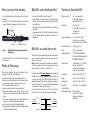
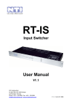
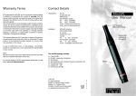
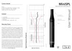
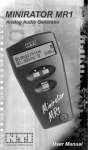
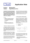
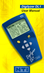
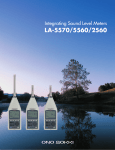
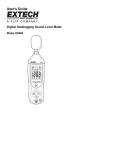
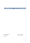
Warranty Terms
NTI guarantees the MiniSPL and its components against defects
in material or workmanship for a period of one year from the
date of original purchase, and agrees to repair or to replace at its
discretion any defective unit at no cost for either parts or labor
during this period.
This warranty does not cover damages caused through accidents,
misuse, lack of care, transit, the attachment or installation of any
components that were not provided with the product, loss of parts,
connecting the instrument to a power supply, input signal voltage
or connector type other than specified, or wrongly polarized
batteries. In particular, no responsibility is granted for special,
incidental or consequential damages.
C ontact Details
Headquarter:
Subsidiary:
This warranty becomes void if servicing or repairs of the product
are performed by any party other than an authorized NTI repair
center or if the instrument has been opened in a manner other
than specified in this manual.
MiniSPL
User Manual
NTI AG
Im alten Riet 102
9494 Schaan
Liechtenstein, Europe
Tel.
+423 - 239 6060
Fax
+423 - 239 6089
E-mail [email protected]
Home www.nt-instruments.com
1/2“ Capsule,
Omni-directional
NTI North America
3520 Griffith Street
St. Laurent
Quebec H4T 1A7
Canada
Tel.
+1 - 514 - 344 5220
Toll free1800 - 661 6388
Fax
+1 - 514 - 344 522
E-mail [email protected]
Status LED,
indicating
On-status
In case of malfunction, take - or ship prepaid - the MiniSPL,
packed in the original box, to the authorized NTI representative
in your country.
For contact-details of the NTI representative please see our web
page: www.nt-instruments.com
The MiniSPL-package includes:
1x
1x
1x
1x
1x
1x
1x
Case MiniSPL
MiniSPL, measuring microphone
Windscreen
Test Certificate with individual frequency response chart
Microphone-holder
Adapter 5/8“ - 3/8“
User Manual MiniSPL
© NTI AG
All rights reserved.
Subject to change without notice.
Release 1.2 / February 2002
Minilyzer, MiniSPL and Minstruments
are registered trademarks of NTI.
2001
Sleeve
MP 2/01 E 100 N 09.01
Note:
Be sure to include a copy of your sales invoice as prove of purchase
date and a detailed description of the fault.
How to insert the battery
M iniSPL with Minilyzer ML1
Technical Data MiniSPL
• To insert the battery, press the push-pin in and slide the
sleeve off.
• Insert one 1.5 V AA size battery according to drawing
below. The polarity is marked on the sticker inside.
• Connect the MiniSPL to the Minilyzer ML1.
• Approximately ten seconds later the Status-LED will
start to flash periodically indicating that the MiniSPL
has switched on.
• An empty battery will be indicated by the non-flashing
Status-LED.
• Simply unplug the MiniSPL after completed operation.
Thus the Status-LED will stop flashing, indicating it is
switched off.
Microphone Type
1/2”, omni-directional,
pre-polarized condenser,
free field transducer
Sensitivity
(20 ±2) mV/Pa,
(-34 ±1) dBV/Pa @ 1 kHz, 20°C
+0.05 dBSPL / °C,
balanced out
Frequency Response
acc. to IEC60651, Type 2,
tolerance curve is shown on
individual calibration certificate
Peak Acoustic Input
130 dBSPL @ 1 kHz
Noise
32 dBSPL, A-weighted
Load Conditions
20 - 200 kOhm balanced,
to achieve this always switch
PHANTOM POWER off.
Power Supply
1x AA battery 1.5 V, battery
lifetime typical 300 hrs,
no phantom power supply,
phantom power resistant
Dimensions
/ 0.87” x 7”
O/ 22 x 180 mm, O
Weight
100 g ( 3.5 oz ) incl. battery
Temperature
0° to +45° C (32° to 113° F)
Humidity
< 90 % R.H., non condensing
1
2
Push-pin
Note:
Calibration-sticker
The MiniSPL does not operate without
the battery.
• Close the MiniSPL. Turn the sleeve so that it is locked by
the push-pin.
Notes & Warnings
To avoid any problems during the operation of the
instrument, follow the rules listed below:
• Use the instrument for the intended purpose only.
• Never connect the instrument to a high voltage output
such as a power amplifier, mains power plug, etc.
• Do not disassemble the instrument.
• Never use the instrument in a wet environment.
• Remove the batteries as soon as they are flat or if the
instrument is not intended to be used for a longer period
of time.
• The use of rechargeable NiCd- or NiMH-batteries is
causing shorter battery lifetime than specified.
• Note the correct polarity of the inserted battery.
• We recommend to calibrate the MiniSPL in yearly intervals
to fulfill the specified sensitivity.
M iniSPL as stand-alone mic
The MiniSPL may be operated as a stand-alone microphone
e.g. connected to a balanced audio-line, a microphoneinput or a sound-card.
Note: Follow the specified load condition to achieve the
flat frequency response. Phantom power causes a lower
load condition, so make sure to switch it off.
At inputs with high DC-input resistance you may find the
MiniSPL not switching on or the delay-time until switching
on may be too long. In this case you have to build up an
adapter according to the below circuit diagram. Please note
that both resistance ’’R’’ should be of equal values within
1% tolerance for good signal balancing.
At unbalanced inputs use pin 1 and 2. Pin 3 shall not be
connected. In this case the sensitivity will be halved.
connect
MiniSPL
Life
Ground
Return
2
1
3
R
connect
audio-input
R = 10 kOhm .. 100 kOhm
Conforms to the
Normative Standards
EMC-Directives:
89/336, 92/31, 93/68
Harmonized Standards:
EN 61326-1