1
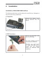
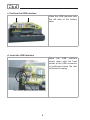
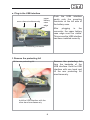
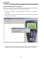
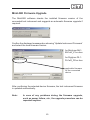
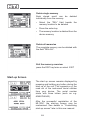
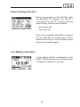
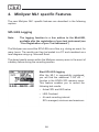
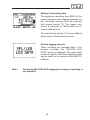
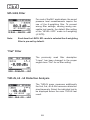
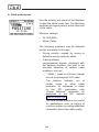
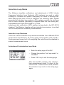
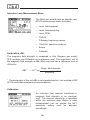
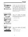
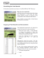
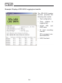
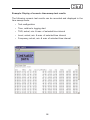
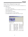
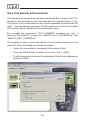
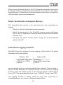
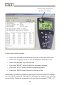
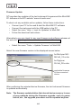
MiniLINK
User Manual
NTI contact details:
NTI AG
Im alten Riet 102
9494 Schaan
Liechtenstein, Europe
Tel.
+423 - 239 6060
Fax
+423 - 239 6089
E-mail [email protected]
Web
www.nti-audio.com
© NTI AG
All rights reserved.
Subject to change without notice.
Release 2.22e / Oct. 2007 / Software V2.22
MiniLINK, Minilyzer, Digilyzer, Acoustilyzer, Minirator, MiniSPL and
Minstruments are trademarks of NTI.
2
Index:
1. Introduction
CE Declaration of Conformity
International Warranty and Repair
Warnings
4
4
5
6
2. Installation
Installation of MiniLINK USB Interface
MiniLINK PC Software Installation
Start the MiniLINK PC Software
MiniLINK Firmware Upgrade
Free Registration of your Test Instrument
7
7
11
12
13
14
3. New ML1 & DL1 Firmware
Memory Function
Start-up Screen
Power Saving Function
Low Battery Indication
15
15
18
19
19
4. Minilyzer ML1 specific Features
SPL/LEQ Logging
SPL/LEQ Filter
“Flat” Filter
THD+N, k2 - k5 Distortion Analysis
Polarity Test Function
Induction Loop Mode
20
20
22
22
22
23
25
5. Digilyzer DL1 specific Features
Event Logger
29
29
6. MiniLINK PC Software
Read Out of Stored Test Results
Visualizing the Test Results
Copying of Test Results and Screenshots
Save Test Results & Screenshots
Delete Test Results of Analyzer Memory
Test Result Logging at the PC
Remote Test Instrument Control with the PC
MiniLINK Tools
30
31
32
32
38
39
39
41
42
7. Troubleshooting
47
3
1. Introduction
Congratulations and thank you for buying NTI’s MiniLINK, a product to support
the documentation of test results from the Minilyzer ML1, the Digilyzer DL1
and the Acoustilyzer AL1 (please refer to the AL1 user manual). This manual
describes the PC Software “MiniLINK“ and includes the new firmware features
of the Minilyzer and Digilyzer. Further information about the analogue,
acoustical and digital handheld analyzers can be found in the NTI web site
“www.nti-audio.com”.
The MiniLINK package includes the following:
1x MiniLINK USB interface
1x Battery cover for Minilyzer ML1 (black)
1x Battery cover for Digilyzer DL1 (blue)
1x CD (PC software, driver, firmware for ML1/DL1)
1x USB cable
1x MiniLINK user manual
CE Declaration of Conformity
We, the manufacturer
NTI AG, Im alten Riet 102, 9494 Schaan
Liechtenstein, Europe
hereby declare that the product MiniLINK, released in 2003, conforms to
the following standards or other normative documents.
EMC-Directives:
Harmonized Standards:
89/336, 92/31, 93/68
EN 61326-1
This declaration becomes void in case of any changes on the product
without written authorization by NTI.
Date:
01.07.2003
Signature:
Position of signatory:
Technical Director
4
International Warranty and Repair
International Warranty
NTI guarantees the functionality of MiniLINK against defects in material or
workmanship for a period of one year from the date of original purchase,
and agrees to repair or to replace at its discretion any defective unit at no
cost for either parts or labor during this period.
Note
Using one MiniLINK USB interface for more than one test instrument is
not permitted. After the installation of the USB interface into a Minilyzer or
Digilyzer, it has to remain inside this test instrument and is not allowed to
be installed into another device. Any actions against this term will cause the
non-validity of the warranty conditions.
Restrictions
This warranty does not cover damages caused through accidents, misuse,
lack of care, the attachment or installation of any components that were
not provided with the product, loss of parts, connecting the instrument to
a power supply, input signal voltage or connector type other than specified
or wrongly polarized batteries. In particular, no responsibility is granted for
special, incidental or consequential damages.
This warranty becomes void if servicing or repairs of the product are
performed by any party other than an authorized NTI service center or if
the instrument has been opened in a manner other than specified in this
manual.
No other warranty, written or verbal, is authorized by NTI. Except as
otherwise stated in this warranty, NTI makes no representation or warranty
of any kind, expressed or implied in law or in fact, including, without
limitation, merchandising or fitting for any particular purpose and assumes
no liability, either in tort, strict liability, contract or warranty for products.
Repair of MiniLINK
In case of malfunction, take - or ship prepaid - your NTI Minilyzer or
Digilyzer with the installed USB interface packed in the original box, to the
authorized NTI representative in your country. For contact-details see the
NTI web page “www.nti-audio.com”.
Make sure to include a copy of your sales invoice as proof of purchase
date. Transit damages are not covered by this warranty.
5
Warnings
The MiniLINK USB interface is designed for the installation into
one ML1 or DL1. It shall not be removed and used in any other
device. The mounting connector may be damaged due to multiple
plug in/off actions.
The pin1 of the XLR input connector and the RCA connector are
grounded. The connection of the test instrument via the USB
interface to the PC causes a test instrument connection to the PC
ground.
Please observe these ground connections at any measurements
of high power amplifier outputs, otherwise the device under test or
the test instrument may be damaged.
The way to safely test any power amplifier output is to connect the
speaker + and - terminals to the balanced instrument pins 2 and 3.
Do not use pin1. Otherwise the USB cable has to be removed for
the measurement. The Minilyzer RCA connector should not be
used for any power amplifier measurements with connected
USB cable.
NTI recommends that any sensitive measurements with low levels
or good THD+N values are carried out without the USB cable
connected. The test results can be stored in the audio analyzer
and transferred to a PC at a later date.
Please observe the common ESD protection measures at the
installation of the MiniLINK PCB interface.
6
2. Installation
Installation of MiniLINK USB Interface
The following instructions must be observed to avoid the any damages on
the instrument during installations:
a. Preparation
Remove the battery cover
and all batteries from the
device.
connector
b. ESD Precautions
Remove the MiniLINK PCB
from the ESD Bag.
Any static voltages must be
removed prior installation.
Therefore you shall touch
the lower, left side battery
contact with your fingers
during the MiniLINK PCB
installation.
7
c. Position the USB interface
Place the USB interface onto
the left side of the battery
case.
d. Insert the USB interface
Move the USB interface
slowly down until the front
corner at the USB connector
is positioned below the test
instrument housing.
front corner positioned below housing
8
e. Plug-in the USB interface
move down simultaneously
upper
battery
case
edge
Push the USB interface
gently onto the mounting
connector at the left side of
the battery case.
After
plugging
in
the
connector, the upper battery
case edge must be visible.
This proves the USB interface
has been installed correctly.
mounting connector
f. Remove the protecting foil
Remove the protecting foil
from the backside of the
USB interface. Hold the USB
interface with one hand and
lift the rear protecting foil
simultaneously.
lift the rear protecting foil
hold the USB interface with the
other hand simultaneously
9
g. Press the USB interface to the housing
Press the USB interface
gently together with the
battery case. It should be
mounted properly in the test
instrument and stick to the
battery case.
The USB interface is mounted permanently inside the
ML1/DL1 and must not be
removed again.
h. Complete the test instrument
close battery
cover
Insert the batteries and use
the new enclosed battery
cover to close the battery
case. Use the blue colored
case for the Digilyzer and the
black one for the Minilyzer.
i. Final check
The USB interface installation
is completed and the test
instrument is ready for
operation.
10
MiniLINK PC Software Installation
a. Switch on the PC with a windows operating system (MiniLINK supports
Windows 98 SE, 2000, ME and XP)
b. Insert the enclosed MiniLINK CD into the CD drive.
c. The MiniLINK software installation starts automatically. Follow the
instructions on the screen.
If the CD auto-start is disabled on the PC, follow the instructions below:
•
Click on “Start -> Run“ at the windows taskbar.
•
Type “d:\setup“ (assuming “d“ is the letter of the CD drive)
•
Confirm with “ok“
After completing the software installation, the MiniLINK CD shall remain
in the CD drive for the next step.
Note:
If the MiniLINK PC software has been previously installed
on the PC, the old version will automatically be removed.
You need to run the set up program again for a new
installation.
d. Use the attached USB cable to connect the test instrument to the PC.
Windows recognizes the new hardware component automatically and
starts the hardware installation assistant.
Follow the instructions of the installation assistant. Please select the
CD drive as source for the USB driver when asked by the installation
assistant.
In case the warning messages “Digital signature not found”, “Do not
install driver”, “not certified driver” or similar come up: Don’t listen to
Microsoft, listen to us and continue with the installation.
11
Start the MiniLINK PC Software
After the successful driver installation, the MiniLINK software can be started
(the audio analyzer needs to be connected with the PC).
a. To start the software follow the windows path “Start -> Program ->
MiniLINK”.
b. The analyzer switches on automatically and the following screen is
displayed on the monitor:
c. The MiniLINK software checks the installed test instrument firmware and
suggests an automatic firmware upgrade of the analyzer if required.
12
MiniLINK Firmware Upgrade
The MiniLINK software checks the installed firmware version of the
connected test instrument and suggests an automatic firmware upgrade if
required.
Confirm the displayed message box showing “Update Instrument Firmware“
and select the new firmware version.
for Minilyzer ML1:
ML1dA_V3.xx.hex
for Digilyzer DL1:
DL1eD_D2.xx.hex
applicable firmware
for the connected
device
After confirming the selected device firmware, the test instrument firmware
is updated automatically.
Note:
In case of any problems during the firmware upgrade,
such as power failure, etc., the upgrade procedure can be
repeated anytime.
13
Free Registration of your Test Instrument
The new firmware includes additional “bonus features“, enabled after the
registration of the test instrument at the NTI web site.
Overview of available bonus features:
Instrument
Function
Display
ML1
Sound pressure logging
(SPL/LEQ) with additional
memory menu
“LOG AS xxx_LOGSPL“
ML1
AL1
DL1
Customized start-up screen
After the startup, the MiniLINK software automatically suggests the
registration of non-registered connected instruments.
Online registration:
The test instrument needs to be connected to the PC. Proceed with the
above automatic registration or alternatively select the MiniLINK menu
“Help -> Register“.
Offline registration:
Register your device at http://registration.nti-audio.com/Registration.php.
Key in your details and the serial number of the device. Read out the
instrument serial number from your device by starting the instrument and
keeping any button pressed. The start up screen remains displayed. The
serial number starts with three letters (such as ANK675A0A2).
After successfully registering your device, you will receive an e-mail
with your registration key within a few minutes. Please insert this key in
the MiniLINK menu “Help -> Register“. The test instrument needs to be
connected to the PC.
14
3. New ML1 & DL1 Firmware
Starting with the following firmware versions the ML1 and DL1 includes
many additional new features:
Minilyzer
Digilyzer
firmware V3.00
firmware D2.00
The most important one is the memory function. The new Minilyzer and
Digilyzer features are described below. Please note, that all new features
applicable for the audio analyzers, ML1 and DL1, are shown and explained
by using the Minilyzer ML1.
Memory Function
MEM (=memory) function
menu bar
The menu bar includes the new memory field to store a measurement as
screenshot on the device itself. At test functions with many numerical test
results, such as the 1/3rd octave analysis or sweeps, the results are stored
in table form at the same time.
15
Each recorded screenshot is automatically saved with a file name consisting
of the test mode and a continuous running number (“xxx“ = running number
from 000 - 999, afterwards starting with 000 again):
•
ML1: “Mxxx_test mode“, e.g. M075_Balance, M076_LOGSPL
•
DL1: “Dxxx_test mode“
Note:
The stored measurements remain available in the memory
even after removing the batteries for longer period of up to
several years.
a. Storing test results
Store screenshots/numerical results:
• Open the menu “MEM”
• Press the enter key
Each recorded screenshot is automatically
stored with a file name consisting of the test
mode and a continuous running number.
Maximum memory:
• Minilyzer ML1: 39 Screenshots
• Digilyzer DL1: 78 Screenshots
(without numerical data)
If no more memory is available, the
message “CANNOT STORE: MEMORY
FULL!“ appears.
b. Display & manage memory
Open memory overview
All previously stored measurements can be
displayed in the memory overview screen:
• Open the menu “MEM”
• Select “VIEW/DELETE”
• Press the enter key
16
Recorded test results
The stored measurements are listed in
continuous order from top to bottom. The
latest recorded measurement is always on
top of the list.
The remaining memory space is displayed
in the right-upper corner of the screen.
Display recorded test results
•
Select any record in the list using the
cursor
•
Press and hold the enter key
•
The recorded measurement is displayed
on the instrument screen.
Note that at the same time the small square
in front of the selected measurement
changes color. This measurement is now
ready for the quick recall mode.
square
Quick recall mode (ML1 only)
After leaving the memory overview the
previously marked memory location can be
displayed by pressing and holding the keys
ESC + ENTER. This feature is very useful
e.g. to compare the actual 1/3rd octave
spectrum with a stored spectrum.
17
Delete single memory
Each stored result can be
individually from the memory.
deleted
•
Select the “DEL“ field beside the
memory location to be deleted
•
Press the enter key
•
The memory location is deleted from the
device memory
Delete all memories
The complete memory can be deleted with
the field “DEL ALL“.
Exit the memory overview
press the ESC key twice or select EXIT
Start-up Screen
The start up screen remains displayed by
pressing and holding any button during the
start up of the unit. This supports e.g. the
read out of the instrument serial number
from your device. The serial number
starts with three letters (such as e.g.
ANK675A0A2).
After the successful registration of the
ML1/DL1 the start-up screen may be
customized. See details in “Customizing
start-up screen” later in this user manual.
18
Power Saving Function
During the operation of the ML1/DL1 with
the MiniLINK PC software, the ML1/DL1
is powered from the PC and the following
power saving functions are disabled:
•
Auto Power Off
•
Auto Light Off
After the PC software MiniLINK is switched
off the ML1/DL1 is continuously further
powered from the PC but the power saving
features are enabled again.
Low Battery Indication
A low battery symbol is displayed in the
“MEM” field of the menu bar to indicate that
a change of batteries is required.
19
4. Minilyzer ML1 specific Features
The new Minilyzer ML1 specific features are described in the following
capture.
SPL/LEQ Logging
Note:
The logging function is a free add-on to the MiniLINK,
available after the registration of your test instrument (see
“Free Registration of your Test Instrument”)
The Minilyzer can record the SPL/LEQ curve flow, e.g. during an event, for
many hours. The results can then be loaded to a PC and visualized as a
level diagram using e.g. Microsoft Excel.
The stored results remain within the Minilyzer memory even in the event of
a battery failure during the recording session.
Start SPL/LEQ logging
After the ML1 is successfully registered,
you will find the additional “LOG AS ...“
function in the LEVEL SPL memory menu.
This feature enables you to record the
following test results:
•
Actual SPL and LEQ value
•
LEQ Overload
•
At each recording interval:
SPL averaged, minimum and maximum
20
Setting of recording time
The maximum recording time (END) of the
sound pressure level logging depends on
the remaining memory and the selected
test interval period (T). The logger may
record a maximum of 1500 points over a
custom defined time.
The test interval period (T) can be defined
by the user in the format hh:mm:ss.
Review logging records
When checking the recorded data in the
memory overview, the “SPL/LEQ LOG
DATA“ screen is displayed. The result table
is stored together with this screenshot and
can be read out by using the MiniLINK PC
software.
Note:
During the ML1 SPL/LEQ logging the change of settings is
not possible.
21
SPL/LEQ Filter
For most of the ML1 applications, the sound
pressure level measurements require the
use of the A-weighting filter. To prevent
wrong filter settings, causing wrong nonusable test results, the default filter setting
of the “LEVEL->SPL” mode is A-weighting
(A-WTD).
Note:
Each time the LEVEL SPL mode is selected the A-weighting
filter is pre-set by default.
“Flat” Filter
The previously used filter description
“Linear“ has been changed to the proper
english term “Flat“ for no filter setting.
THD+N, k2 - k5 Distortion Analysis
The THD+N menu measures additionally
the 2nd, 3rd, 4th & 5th harmonics distortion
simultaneously. Select the individual test to
be displayed below the main THD+N test
result.
22
Polarity Test Function
The polarity test function detects the correct cable and speaker polarity in
combination with the Minirator MR1. The Minilyzer provides the following
test configurations:
a. Speaker polarity test
Feed the speaker system with the polaritytest signal of the Minirator and adjust the
level (at MR1 or amplifier) that the test
signal is good to hear.
Minilyzer settings:
•
IN:MIC (INT), using the internal mic of
the Minilyzer ML1
•
IN:XLR/RCA, using an external mic,
such as the MiniSPL
Choose the polarity test frequency range:
Note:
•
FULL/MID, for tests with wide band
speakers
•
WOOFER, for tests with woofers
Please note the polarity testing is a simplified measurement
of a very complex signal phasing. Drivers, speakers and
cross-overs cause severe phase shifts of the audio signal.
The polarity of various speakers within the same cabinet
can be different. This is not a problem nor caused by bad
speaker design.
Polarity testing is useful for checking the correct wiring of
similar speaker systems.
23
b. Cable polarity test
Use the polarity test signal of the Minirator
to feed the cable under test. The Minilyzer
analyzes the signal polarity at the other end
of the cable.
Minilyzer settings:
•
IN: XLR/RCA,
•
Mode: Cable
The following problems may be detected
quickly and easily in this way:
•
Wrong polarity, caused by wrong or
defective wiring inside the cable
•
Cable problems
unsymmetrical signals, displayed with
the balance indicator, can lead to the
accurate detection of various cable
problems, such as
-
“–UBAL–“ leads to a broken internal
wire at a symmetrical XLR cable
-
The balance indicator out of
center leads to other cable
problems as explained in detail
in the NTI application note
“Signal Balance“ (available for
download at the NTI website
www.nti-audio.com).
The level measurement is very useful
for applications, such as testing of
multicore cables, providing additional
information about the cable quality.
24
Induction Loop Mode
The Minilyzer simplifies verifications and adjustments of AFILS (Audio
Frequency Induction Loop Systems). AFIL systems are used in public
buildings to increase the speech intelligibility for users of hearing aids.
Most hearing aids have a built in magnetic coil receiving audio signals
generated by induction loop systems. AFIL systems consist of a wire loop
and a current amplifier generating a magnetic field into the hearing aid,
modulated by the audio input signal, e.g. voice.
Adjustment and verification of AFIL systems is described in the IEC 60118
standard. The Minilyzer, together with an induction loop receiver, is an ideal
tool to accomplish the necessary measurements.
Induction Loop Receivers
There are various induction loop receivers available from different AFILS
components manufactures. All known types work together with the ML1.
Some receivers have a built in A-weighting filter, which must be disabled to
prevent measurement errors.
Activation of the Induction Loop Mode
•
Enter the setup page of the ML1
•
Change the position “Ind. loop mode” to
“ENABLE”
•
Press ESC key to exit the setup page
After this the ML1 restarts in the induction
loop measurement mode. To return to the
common ML1 measurement mode, disable
the induction loop mode in the setup page
again.
25
Induction Loop Measurement Menu
The Minilyzer restarts with an specific new
AFILS measurement menu including
•
Level, fast weighted
•
Level, slow weighting
•
Level, PPM
•
THD+N
•
F-Sweep, frequency sweep
•
1/3rd Oct, spectrum analyzer
•
Scope
• Calibrate
Units mA/m, dBL
The magnetic field strength is measured in A/m (Ampere per meter).
AFIL systems use 400mA/m as a reference level. The logarithmic unit of
the magnetic field strength is dBL (dB Loop) and has a reference level of
400mA/m.
dBL1
= 20 * log
Magn. field strength
400mA/m
The designator of the unit dBL is not standardized jet - but resulted of IEC
60118 committee members recommendations.
1
Calibration
An induction loop receiver transforms a
magnetic field strength to an electrical
level. The receiver sensitivity is specified
within the technical data. Before a valid
measurement can be started the ML1
sensitivity setting must be adjusted
accordingly.
26
Filters
The ML1 has a built-in A-weighting and
a HP400 (high pass 400Hz) filter, which
may be activated using the filter menu.
For detailed test requirements please
refer to the IEC 60118 standard. The
HP400 filter has an excellent rejection of
mains frequencies, which sometimes is a
dominant part of the signal received by the
induction loop receiver.
Level Fast, Level Slow
Level of the magnetic field strength
measured in accordance to IEC60804
(sound pressure level time weighting) with
the following integration times:
•
Level Fast: 125ms
•
Level Slow: 1s
Level PPM
Level of the magnetic field strength
measured with a ppm like peak detector
(type IIa).
•
Integration time: 10 ms
•
dBLp = dB Loop peak
27
THD+N
Total harmonic distortion + noise
Please refer to the Minilyzer user manual
for more details.
FSweep
Frequency Sweep recording
Please refer to the Minilyzer user manual
for more details. The frequency tracking will
not work if mains frequency components
dominate the input signal. Activating
the HP400 filter will attenuate all main
frequency components and a frequency
recording is possible.
1/3rd Octave
1/3rd octave spectrum analyzer
This function shows the spectrum of the
input signal in 1/3 octave bands. Please
refer to the Minilyzer user manual for
more details. The ML1 input ranging is not
necessary in the induction loop mode and
therefore not included.
Scope
Time domain of the input signal in A/m
Please refer to the Minilyzer user manual
for more details.
28
5. Digilyzer DL1 specific Features
Starting with the DL1 firmware D2.00 the Digilyzer includes the features
already described in “New ML1 & DL1 Firmware” such as
•
Memorizing of screenshots and measured data
•
Online logging
•
Customizing of start-up screen.
Event Logger
Starting with the firmware D2.10, the Digilyzer supports the read out of all
numerical event logger data to the computer.
Please note the specific DL1 event logger display-masking feature is not
applicable. All event records are memorized at anytime.
29
6. MiniLINK PC Software
The MiniLINK PC software enables the transfer of stored measurements
from the Minilyzer / Digilyzer to the PC and the online data logging.
•
To start the software follow the windows path “Start → Program →
MiniLINK”.
•
The analyzer switches on automatically and the following screen is
displayed on the monitor:
The test instrument is powered by the USB interface and therefore switches
on by itself. During the operation with the connected USB interface the
batteries should not be removed from the device.
30
Read Out of Stored Test Results
The analyzer memory is automatically transferred to the PC and visualized
with small screenshots at the MiniLINK memory window.
Note:
The MiniLINK memory window remains empty when no
test results are stored within the instrument. Otherwise,
use the PC mouse to click onto the “ML1 Memory“ tab to
initiate and update the data memory window.
The test instrument display at the PC is synchronized to the actual LCD
screen display of the connected audio analyzer. The title bar reads the
serial number and firmware version of the test instrument.
MiniLINK PC
software release
version
firmware of
connected audio
analyzer
serial number of
connected audio
analyzer
31
synchronized display
Visualizing the Test Results
All stored screenshots are shown in the MiniLINK tab “ML1 Memory“.
Big view of screenshots
A double click on the screenshot will enlarge
this screenshot. In this mode the menu
allows printing, saving or copying of the
screenshot or the numerical test results.
Any available numeric table is listed below
the big view screenshot.
Copying of Test Results and Screenshots
The displayed screenshots can directly be
copied into reports for documentation.
•
Select the menu “Edit -> Copy Bitmap”
to choose the graphics or select the
menu “Edit -> Copy Text” to choose the
numerical measurement data
•
Insert the clipboard into the reporting
document with “Ctrl + V”, such as
Excel,...
Alternatively import the stored “*.txt” file,
including the numerical measurement data,
e.g. to Microsoft to Excel by using the Excel
import assistant.
In the 1/3rd octave measurement screen
the following additional numeric data is
displayed below the big view screenshot:
•
1/3 octave frequencies
•
Level
32
Additional display of Minilyzer test results:
•
Logged sound pressure level records are displayed with the “SPL/LEQ
LOG DATA“ screenshot. The detailed test records are saved behind the
screenshot. Double-click onto this screenshot to enlarge the screenshot
and display the numeric test records.
•
TimeSweep mode: The Minilyzer is able to record the results within the
time sweep mode. All numeric data is recorded and available by double
clicking on the “TIMESWEEP DATA“ screenshot. The time sweep
records are stored in a different memory bank than the other stored
measurements. Therefore, this screenshot is displayed in a different
color at the last position.
SPL/LEQ LOG DATA
TIMESWEEP DATA
Arrows indicating additional
numerical test results are stored
together with this screenshot
33
Example: Display of SPL/LEQ Logging test results
The SPL/LEQ logging
function provides the
following test results:
•
Test configuration
•
Time, relative
logging start
•
Actual SPL
LEQ value
•
At each recording
interval:
to
and
SPL averaged, min.
and maximum
•
34
LEQ Overload
Example: Display of numeric time-sweep test results
The following numeric test results can be recorded and displayed in the
time sweep mode:
•
Test configuration
•
Time, relative to logging start
•
THD, actual, min. & max. of selected time interval
•
Level, actual, min. & max. of selected time interval
•
Frequency, actual, min. & max. of selected time interval
35
Additional display of Digilyzer test results:
The event logger records are displayed with the “EVENT LOG DATA“
screenshot. The detailed test records are saved behind the screenshot.
Double-click onto this screenshot to enlarge the screenshot and display
the event logger records. These data are stored in a different memory
bank than the other stored measurements. Therefore, this screenshot is
displayed in a different color at the last position.
EVENT LOG DATA
Arrows indicating additional
numerical test results are stored
together with this screenshot
36
Example: Display of Digilyzer Event Logger results
The following numeric test results can be recorded and displayed in the
event logger mode:
•
Test configuration
•
Time, relative to logging start
•
Event Count, number of irregularities of the digital input signal during
each recording interval
•
Group, listing the event category
•
Event, exact description of signal irregularity
•
Info, detailed listing of recorded events at channel A and B
37
Save Test Results & Screenshots
The displayed screenshots can be saved as bitmap files (*.bmp) to the PC’s
hard drive. Any available numeric test data will be saved as text files (*.txt).
The format of the saved data are test results separated by blanks and the
point “.” used as decimal separator. The file names are the first six (6) digits
of the device serial number and the screenshots name.
For example the screenshot “M011_FSWEEP” recorded e.g. with a
Minilyzer S/N ANK675 is saved as “ANK675_M011_FSWEEP.bmp” and
“ANK675_M011_FSWEEP.txt”.
This enables to store various test results of more audio analyzers on the
same PC. Save the stored test results as follows:
•
Select the screenshots to be saved in the memory field.
•
Press the SAVE button or select in the menu “File -> SAVE“.
•
The following menu below will be displayed. Select the configuration
and press SAVE.
38
When saving the screenshots to the PC the same memorized values can
be deleted at the test instrument automatically. Just select in the above
displayed menu “Delete files in instrument memory after save” to empty the
test instrument memory simultaneously.
Delete Test Results of Analyzer Memory
The memorized test results in the test instrument can be deleted as
follows:
•
Directly in the test instrument memory overview
•
Select the screenshot in the MiniLINK memory screen and press
DEL on the PC keyboard or using the delete function of the MiniLINK
memory menu
•
Selecting the delete function when saving the screenshots/test
results to the PC
Test Result Logging at the PC
MiniLINK allows the continuous online logging of test results. The actual
test results of the test modes
Minilyzer ML1
Digilyzer DL1
• Level RMS, REL, SPL • Bitstatistic
• THD+N, vu + PPM
• Level RMS, Level Peak
• Balance
• THD+N
can be logged online in customer defined time intervals. This test data is
saved into the MiniLINK PC software directly. At the end of the logging
process, press the “SAVE” button to save the test results in ASCII format
to your PC. The saved data file name is e.g. “ANK675_PcLog_Level SPL”.
The logging function is ideally suited for long term monitoring or
troubleshooting, e.g. in repair or broadcast applications.
39
icon for direct copying of
present screenshot
To log online results, please:
•
Select the requested measurement function at the test instrument
•
Select the “Logging“ screen in the MiniLINK PC Software menu
•
Select the required log time intervals
•
Press the “START” button to start the test result logging
•
Press the “STOP” button to end the logging process
•
Press the “SAVE” button to save the record to file
Additionally the present screenshot displayed on the MiniLINK PC software
can be directly copied to clipboard by pressing the marked icon with the
mouse button. Paste the screenshot into any files by pressing “CTRL + V”.
40
Remote Test Instrument Control with the PC
MiniLINK supports the remote control of the analyzer from a PC. Just click
on the displayed test instrument and all keys can be operated with the
below listed keys at the PC keyboard or using the mouse.
Click into these areas
to change the screen
selection
(e.g. SPL ↔ RTA)
On/Off: Ctrl + P
Light: Ctrl + L
ESC
Arrow keys & enter
“Shift ←” or “shift →” or the above indicated areas allow to change the
screen selection of the enabled measurement function.
41
MiniLINK Tools
The MiniLINK PC software includes many useful tools as follows:
•
LCD Fullscreen
•
Update Firmware
•
Crossgrade Firmware
•
StartUp Screen
42
LCD Fullscreen
The actual test instrument display can be shown on the PC monitor in a full
screen mode.
To enter the full screen mode:
• Select the menu “Tools → FullScreen“ at MiniLINK
or click onto the
symbol.
To exit the full screen mode:
• Press the “Q” button on the PC keyboard
or simply click into the screen with your PC mouse.
icon for large
screen display
43
Firmware Update
NTI provides free updates of the test instrument firmware and the MiniLINK
PC software at the NTI website “www.nti-audio.com”.
To check out any available online updates, follow these instructions:
• Connect your PC to the web & start the MiniLINK PC software
• Connect the instrument with the USB cable to the PC
• Select the menu “Help -> Look for Updates“ at MiniLINK
• Follow the download instructions
Alternatively you can check for any new firmware and software releases at
the web site “http://registration.nti-audio.com/VersionCheck.php”.
•
Select the menu “Tools -> Update Firmware“ at MiniLINK
Select the new firmware version in the displayed screen below:
for Minilyzer ML1:
ML1dA_V3.xx.bin
for Digilyzer:
DL1dA_D2.xx.bin
applicable firmware
for the connected
device
After confirming the selected device firmware, the test instrument firmware
is updated automatically.
Note: The firmware update deletes the internal device memory. In case
of any problems during the firmware upgrade, such as power
failure, etc., the upgrade procedure can be repeated anytime.
44
Firmware Crossgrade
The Acoustilyzer AL1 and the Minilyzer are based on the same hardware
platform with different specific firmware installed. The available crossgrade
packages allow to install the ML1 firmware into the AL1 or to install the
AL1 firmware into the ML1. The Crossgrade function can be enabled by
installing the option “ML1-AL1 Crossgrade”.
Note: The firmware crossgrade deletes the internal device memory.
Customizing the Startup Screen
The MiniLINK PC software supports the transfer of customized start-up
screens to the test instruments. The personally defined start-up screen will
be displayed instead of the factory logo every time the test instrument is
switched on.
45
Open the “Set Startup Screen” window by using the menu “Tools ->
StartupScreen“ at MiniLINK. The panel “Set Startup Screen” displays a
sample default factory startup screen. The white center area (100 x 32
pixels) can be customized by the user. The remaining top & bottom gray
area is fixed and cannot be altered.
Guideline to define the new start-up screen:
•
Use a pre-defined picture. The MiniLINK PC software will convert it to a
100x32 pixel black & white picture automatically. The following file types
can be used as start-up screens: *.pcx;*.bmp;*.dic;*.rle;*.ico;*.wmf
•
Alternatively create a new start-up screen yourself using any picture /
paint programs, such as “Microsoft Paint”. Set the file size to 100x32
pixel and insert any text or graphics for the start-up screen. Save the file
as “*.bmp* format.
•
Press the button “Load Image” to select the file containing the new start
up screen.
•
The start-up screen preview is displayed on the PC monitor.
•
Press the button “Send to Device” to transfer the file to the device
•
The audio analyzer is switching off and on automatically, so you can
check out the new start-up screen by yourself immediately.
Sample start-up screens:
46
7. Troubleshooting
a. Numeric data import of “*.txt” files to Excel
Problem:
The numbers are recognized as text only at the import of numeric test
results to e.g. Microsoft Excel, so you cannot create tables or use the data
for further calculations.
Solution:
The MiniLINK data files uses blanks inbetween test results and the “.” as
decimal separator. Please set the decimal separator to “.” at the import
procedure of these numeric test results into e.g. Microsoft Excel.
Alternatively you can use copy -> paste in the big view mode, select
the menu “Edit -> Copy Text” and paste the data into an open Excel
document.
b. Registration
Problem:
The registration of your instrument does not work.
Solution:
Check out the latest available firmware and software releases on the web
site “http://registration.nti-audio.com/VersionCheck.php”.
In case you are using older releases please download the latest versions
and try the registration again.
47
Minilyzer ML1
Analog Audio Analyzer
Acoustilyzer AL1
Acoustical Analyzer
MiniSPL
Measurement Mic
Minirator MR-PRO
Analog Audio Generator
Digilyzer DL1
Digital Audio Analyzer
MiniLINK
PC Interface & Software
www.minstruments.com
MI E 1000 WE 10.07
Overview Minstruments Products:


![[Insert the picture here]](http://vs1.manualzilla.com/store/data/005750886_1-61b7896b0a61bec1f004b64a994fc9d3-150x150.png)