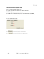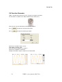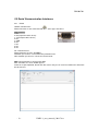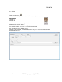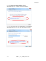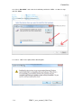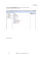
1
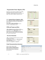
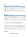
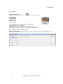
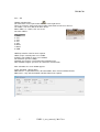
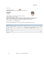
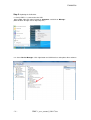
UM-004708
17 Hatidhar st. Ra’anana
43665, Israel
Fax: 09-7417422
Tel: 09-7417411
www.adcom.co.il
UDEC-1
Universal Debug Center
User Manual & Quick Start
UM-004708
-1-
UDEC-1_user_manual_130117.doc
UM-004708
Revision A
Version
1.0
1.1
1.2
-2-
Issued By
Eli Moshe
Yoav Katz
Yoav Katz
Issue Date
20.9.2012
2.12.2012
17.01.2013
Comments
New Product
Updated GUI
Upgrade current limit
UDEC-1_user_manual_130117.doc
UM-004708
Table of Contents
Table of Contents ........................................................................................................................ 3
Quick Start .................................................................................................................................. 4
Programmable Power Supplies (PPS) ......................................................................................... 5
2.1 Isolated Power Supplies (IPS) .............................................................................................. 5
DVM and Frequency Meter.......................................................................................................... 5
Function Generator ..................................................................................................................... 5
Serial Communication Interfaces ................................................................................................. 5
SPI .............................................................................................................................................. 6
I²C............................................................................................................................................... 6
User Manual................................................................................................................................ 7
1. Introduction ............................................................................................................................ 7
1.1 Purpose................................................................................................................................. 7
1.2 Scope .................................................................................................................................... 7
1.3 What's in the Box? ................................................................................................................. 7
1.4 First Steps ............................................................................................................................. 7
1.5 UDEC-1 Features .................................................................................................................. 7
UDEC-1 Front Panel ................................................................................................................... 8
UDEC-1 Back Panel .................................................................................................................... 8
2. Using the UDEC-1 ................................................................................................................... 9
2.1 Programmable Power Supplies (PPS) ................................................................................... 9
2.2 Isolated Power Supplies (IPS) ............................................................................................. 10
2.3 DVM and Frequency Meter .................................................................................................. 11
2.4 Function Generator.............................................................................................................. 12
2.5 Serial Communication Interfaces ......................................................................................... 13
Appendix A
-3-
UDEC-1_user_manual_130117.doc
UM-004708
Quick Start
First Step
Insert the CD into a PC drive and run UDEC-1 Ver x.xx.msi to install the UDEC-1 driver. Once
completed the UDEC-1 ICON residing on your desktop like:
Click on the icon to activate UDEC-1.
You will get the below screen.
-4-
UDEC-1_user_manual_130117.doc
UM-004708
Programmable Power Supplies (PPS)
All 4 PPS are connected to a common return (GND).
Total power of the 4 PPS cannot exceed 10W.
The UDEC-1 control software alerts for any excess of
Power and disable the option of update the PPS.
2.1 Isolated Power Supplies (IPS)
The +12VDC and -12VDC supplies up to 330mA and
share a common return which is isolated from all
other returns.
The 3.3VDC supplies up to 500mA
and it’s return is isolated from all other returns.
The IPS is controlled from the GUI.
DVM and Frequency Meter
UDEC-1 DVM and Frequency Meter share the
same input probe. They also share the same return
with the PPS. Use the Meter IN BNC on the
Front Panel to connect the DVM/Frequency Meter
Probe. Select the required measurement by cliking
the relevant function window.
Function Generator
UDEC-1 Function Generator creates Sine, Triangle
and Square waveforms.
The waveform is available at the Wave Out BNC
on the Front Panel.
Sine and Triangle amplitude is ~1.8V±0.1V.
Square wave amplitude is ~10V±0.5V.
Serial Communication Interfaces
RS232, UART, RS422, RS485
After activation, the following screen
appears. Select the required protocol,
format and data source and you can
start Transmit and Receive data from
the other device.
-5-
UDEC-1_user_manual_130117.doc
UM-004708
SPI
UDEC-1 can act as Master or Slave device at maximum speed of 15Mbps.
After activation, the screen bellow appears.
I²C
After activation, the screen bellow appears
UDEC-1 can be either Master or Slave
CAN
Communication protocol may be different with different devices. All protocol share 11 or 29 bytes for
Identifier and 0÷8 bytes of message.
UDEC-1 GUI enables inserting protocol variables to acomodate most of the devices.
After activation, the screen bellow appears.
End of Quick Start
-6-
UDEC-1_user_manual_130117.doc
UM-004708
User Manual
1. Introduction
1.1 Purpose
The purpose of this document is to guide the user through the functional usage of the UDEC-1.
1.2 Scope
The Universal Debug Embedded Center - UDEC-1- serves as a debug and validation tool for every
engineer and technician in the electronic lab.
The UDEC-1 is also a production floor tool for on board programming and control of devices
UDEC-1 supports In System Programming (ISP) and debugging utilizing UART, RS232/422/485, SPI,
CAN or I²C bus.
User friendly GUI enables navigating between the UDEC-1 features
1.3 What's in the Box?
UDEC-1 box contains the following:
The UDEC-1
12VDC/2A Wall Mount Power supply
USB cable
CD with the UDEC-1 utility software and User Manual
1.4 First Steps
Insert the CD into a PC drive and run Installation (see Appendix A)
Connect the PS to the Power Jack at the rear side of the box and turn power ON.
Connect the USB cable between the UDEC-1 and the PC USB input.
An audio tone acknowledges that the UDEC-1 is connected and ready for use.
1.5 UDEC-1 Features
UDEC-1 supports the following features:
4 Programmable Power Supplies 0.8-5.3VDC/1A each
Isolated fixed +/-12VDC/330mA Power Supply
Isolated fixed 3.3VDC/500mA Power Supply
DVM – 0÷45V
Frequency Meter - 0÷10MHz
Function Generator – 0÷2MHz
-7-
UDEC-1_user_manual_130117.doc
UM-004708
Interfaces:
RS232
RS485
RS422
UART
SPI
I²C
CAN
The paragraphs below describe how to use each of the UDEC-1 features.
UDEC-1 Front Panel
UDEC-1 Back Panel
-8-
UDEC-1_user_manual_130117.doc
UM-004708
2. Using the UDEC-1
2.1 Programmable Power Supplies (PPS)
There are 4 programmable power supplies in the range of 0.8-5.3VDC/1A.
All 4 PPS are connected to a common return (GND).
Total power supplied by all PPS 10W
Voltage programmable
0.8÷ 5.3VDC
Current programmable
100÷ 1A
If current exceeds the limit in any one of the PPS by 5%, all 4 PPS are disconnected.
If voltage exceeds the limit in any one of the PPS by 5%, all 4 PPS are disconnected.
The PPS that exceeds its limit is displayed by Blinking Red LED on the GUI.
All other PPS LEDS blink Green.
Total power supplied by the 4 PPS cannot exceed 10W.
The control software alerts for any excess of power and disconnects all 4 PPS.
To activate an output – Fill the check box of the PPS and key-in the
required voltage and current limit.
Press
to output the
programmed voltage to the
output Banana.
Press
to disconnect
all 4 PPS from their outputs.
-9-
UDEC-1_user_manual_130117.doc
UM-004708
2.2 Isolated Power Supplies (IPS)
There are 3 isolated fixed Power Supplies (IPS).
The +12VDC and -12VDC share common return which is isolated from
PPS ground return.
The ±12VDC supplies up to 330mA from each output.
The 3.3VDC return is isolated from all other returns. The 3.3VDC supplies up to 500mA.
If maximum current exceeds its limit, the IPS will be disconnected and it's LED will turn RED.
The IPS is controlled from the GUI.
Press
to connect all IPS to their output bananas.
Press
to disconnect all IPS from their output bananas.
- 10 -
UDEC-1_user_manual_130117.doc
UM-004708
2.3 DVM and Frequency Meter
UDEC-1 DVM and Frequency Meter share the same input probe.
The probe is a standard 1:1 Scope probe.
They also share same ground return with the PPS.
Use the Meter IN BNC on the Front Panel to connect the
DVM/Frequency Meter Probe.
Select the required measurement by pressing the function window.
If DVM function is selected, the Frequency Meter function is Grayed
Out and is Inactive as seen below. If Frequency Meter function is selected, the DVM function is
Grayed Out and is Inactive.
Voltage measurement range: 0÷45VDC
Resolution: ±1%.
Input impedance: 5MΩ
The user can save the measured values vs. time in a log file for further analysis.
Frequency measurement range: 0÷10MHz
Measurement threshold: 200mV
Measurement accuracy: ±0.1%
- 11 -
UDEC-1_user_manual_130117.doc
UM-004708
2.4 Function Generator
UDEC-1 Function Generator creates Sine, Triangle and Square waveforms.
The waveform is available at the Wave Out BNC on the Front Panel.
From the GUI select the Waveform and Frequency required.
Press
to output the waveform to the BNC.
Press
to stop the waveform generation.
Synthesizer resolution: 28 bit (~0.1Hz)
Output DAC resolution: 10 bit
Sine and Triangle amplitude is 1.8V±0.1V.
Square wave amplitude is 10V±0.5V.
Sample of waveforms outputs snapshots are shown below.
- 12 -
UDEC-1_user_manual_130117.doc
UM-004708
2.5 Serial Communication Interfaces
2.5.1 RS232
Toolbar activation Icon:
RS232 connector is male connector with Pin 1 at the upper left corner.
Connector Pins
1. NC
2. RX (Input from other device)
3. TX (Output to other device)
4. NC
5. GND
6. NC
7. NC
8. NC
9. NC
NC - Not Connected
RS232 maximum speed is 921600bps.
Standard speed can be selected from the pull-down menu.
Non-standard speed can be selected in Custom mode
Note: Connector body is connected to GND.
After activation, the screen bellow appears.
Select the required protocol, format and data source and you can start Transmit/Receive data from
the other device.
- 13 -
UDEC-1_user_manual_130117.doc
UM-004708
2.5.2 UART
Toolbar activation Icon:
UART connector is a 4 pin male header with Pin 1 at the right corner.
Connector Pins
1. VREF Input
2. RX (Input from other device)
3. TX (Output to other device)
4. GND
VREF input defines VOH/VIH level required.
VREF accepts external power 3.3÷5.5VDC.
If VREF is left OPEN, I/O levels are LVCMOS
UART maximum speed is 3Mbps.
Standard speed can be selected from the pull-down menu.
Non-standard or higher speed can be selected in Custom mode
After activation, the screen bellow appears.
Select the required protocol, format and data source and you can start Transmit/Receive data
to/from the other device.
- 14 -
UDEC-1_user_manual_130117.doc
UM-004708
2.5.3 RS485
Toolbar activation Icon:
RS485 connector is a 2 pin male header with Pin 1 at the right corner.
Connector Pins
1. RS485 - B
2. RS485 – A
120Ω termination exists between pins A and B.
RS485 maximum speed is 3Mbps.
Standard speed can be selected from the pull-down menu.
Non-standard or higher speed can be selected in Custom mode
After activation, the screen bellow appears.
Select the required protocol, format and data source and you can start Transmit/Receive data
to/from the other device.
- 15 -
UDEC-1_user_manual_130117.doc
UM-004708
2.5.4 RS422
Toolbar activation Icon:
RS422 connector is a 4 pin male header with Pin 1 at the right corner.
Connector Pins
1. RS422 RXA
2. RS422 RXB
3. RS422 TXZ
4. RS422 TXY
120Ω termination exists between pins RXA and RXB.
RS422 maximum speed is 3Mbps.
Standard speed can be selected from the pull-down menu.
Non-standard or higher speed can be selected in Custom mode
After activation, the screen bellow appears.
Select the required protocol, format and data source and you can start Transmit/Receive data
to/from the other device.
- 16 -
UDEC-1_user_manual_130117.doc
UM-004708
2.5.5 SPI
Toolbar activation Icon:
SPI connector is male 8 pin header with Pin 1 at the right corner.
There are 3 SS pins (Slave Select) that enable connection to 3 SPI slave devices.
The UDEC-1 can act as Master or Slave device.
When UDEC-1 is a Slave, SS1 acts as the
SS of the UDEC-1.
Connector Pins
1. VREF
2. SS3
3. SS2
4. SS1
5. SCK
6. MISO
7. MOSI
8. GND
VREF input defines VOH/VIH level required.
VREF accepts external power 3.3÷5.5VDC.
If VREF is left OPEN, I/O levels are LVCMOS.
SPI maximum speed is 15Mbps.
Standard speed can be selected from the pull-down menu.
Non-standard or higher speed can be selected in Custom mode
After activation, the screen bellow appears.
Select SPI Mode – Master/Slave.
Mode Master – required Baud rate, SPI Clock Mode, Slave Select and Data Format.
Mode Slave – only SPI Clock Mode and Data Format are required.
- 17 -
UDEC-1_user_manual_130117.doc
UM-004708
2.5.6 I²C
Toolbar activation Icon:
I²C connector is male 4 pin header with Pin 1 at the right corner.
Connector Pins
1. VREF
2. SDA
3. SCL
4. GND
VREF input defines VOH/VIH level required.
VREF accepts external power 3.3÷5.5VDC.
If VREF is left OPEN, I/O levels are LVCMOS.
After activation, the screen bellow appears
UDEC-1 can be either Master or Slave
You may select the Slave address.
The maximum speed is 400Kbps
You may select the operation for read/write.
In master read operation you may select the data size to read:
• Byte – one Byte in a transmission.
• Page – number of bytes according the amount parameter.
You may select Data Format either Hex or Ascii
After filling the required parameters in the screen you can start Transmit (Write oeration) data or
Receive (Read operation) data by clicking the read button
- 18 -
UDEC-1_user_manual_130117.doc
UM-004708
2.5.7 CAN
Toolbar activation Icon:
CAN connector is male 2 pin header with Pin 1 at the right corner.
Connector Pins
1. CAN-Hi
2. CAN-Lo
120Ω termination exists between pins CAN-Hi and CAN-Lo
CAN bus maximum speed is 1Mbps.
Communication protocol is based on BOSCH CAN bus protocol. Although it may be different with
different devices. All protocol share 11 or 29 bytes for Identifier and 0÷8 bytes of message.
UDEC-1 GUI enables inserting protocol variables to acomodate most of the devices.
After activation, the screen bellow appears.
Select the CAN protocol and you can start Transmit/Receive data to/from the other device
- 19 -
UDEC-1_user_manual_130117.doc
UM-004708
Appendix A
Setup USB driver for windows 7, Vista, XP
Step 1: UDEC-1 Utility Installation
Run UDEC-1 Version x. xx.msi file.
Remember the installation path you will need at in step 2
- 20 -
UDEC-1_user_manual_130117.doc
UM-004708
Step 2: Updating the USB driver
2.1 Verify UDEC-1 is connected to the USB
Go to “start”, right click mouse button on “Computer” and click on “Manage”.
(With windows XP right click on My Computer)
2.2. Go to “Device Manager”. Click right button on COM Interface and update driver software.
- 21 -
UDEC-1_user_manual_130117.doc
UM-004708
2.3. Select “Browse my computer for driver software”.
(With windows XP select “Install from a list or specific location”)
2.4. Select: “Let me pick from a list of device drivers on my computer”.
(With windows XP select don't search I will choose the driver to install)
- 22 -
UDEC-1_user_manual_130117.doc
UM-004708
2.5. Select: “Show All Devices” and click Next.
- 23 -
UDEC-1_user_manual_130117.doc
UM-004708
2.6. Select: “Have Disk” and select the installation path for the UDEC-1 as done in step 1
and click “Next”.
2.7. Select: “Yes” in the Update Driver Warning box.
- 24 -
UDEC-1_user_manual_130117.doc
UM-004708
2.8 . Expect this note
- 25 -
UDEC-1_user_manual_130117.doc
UM-004708
2.9. Go back to “Device Manager” and make sure your driver is updated
Disconnect USB cable and connect it back.
End of installation
- 26 -
UDEC-1_user_manual_130117.doc