1
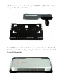
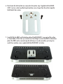
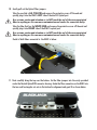
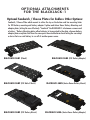
BLACKJACK-1
Camera Mount Neutrik
opticalCON Interface for
Blackmagic ATEM Camera Converter
User Manual • Installation Instructions
SAFETY PRECAUTIONS
1.To prevent fire or shock hazard, do not expose this equipment to an environment of high
humidity and/or dust. Do not use in an unprotected outdoor installation or any area
classified as overly damp or wet.
2.The temperature for installation should be kept between 0°C ~ 60°C. Avoid direct sunlight exposure or extreme changes of temperature over a short period of time.
3. Do not disassemble the unit or put it on an unstable base
4. Do not drop it and avoid heavy impact.
5.Ventilation: Any openings in the enclosure are provided for ventilation and to ensure
reliable operation of the unit and to protect it from overheating. These openings, if any,
must not be blocked or covered. This unit should not be placed in a built-in installation
unless proper ventilation is provided.
6.Cleaning: Unplug the unit from the mains outlet before cleaning. Do not use liquid cleaners or aerosol cleaners, only use a damp cloth.
7.Do not overload outlets and extension cords as this may result in a risk of fire or electric
shock.
8.Enclosure Entry of any kind is dangerous. Never push objects of any kind, including
liquids, into this unit through openings as they may touch dangerous voltage points or
short-out parts that could result in a fire or electric shock.
9.Service: Do not attempt to open or service this unit yourself as opening or removing
covers may expose you to dangerous voltage of other hazards.
10.There are no user-serviceable parts inside the unit. If the unit requires service please
contact your authorized dealer, or an authorized repair service company.
Below is what a finished assembled BLACKJACK-1
hosting platform will look like once complete:
ASSEMBLY INSTRUCTIONS:
Black Magic Camera Converter (BMCC) Preparation
There are 2 steps for this procedure:
1. F lip the BMCC over and remove the belt clip which is being held in place by two socket cap
allen keyed machine screws.
2. S tow the screws away for belt clip re-installation if the BMCC is ever removed from the
BLACKJACK-1 hosting platform.
ASSEMBLY INSTRUCTIONS Continued:
BLACKJACK-1 Hosting Platform Preparation
There are 12 steps for this procedure:
1. Set BLACKJACK-1 unit on flat surface as shown below.
2. P lease note and be aware of the two LC Single-Mode Optical Fiber cables that were pre-installed into the Neutrik OpticalCON connector housing. Note where they are protruding into
the space where the BMCC will be installed inside the BLACKJACK-1. You can see them if
you peer inside between the top and bottom of the hosting platform as shown below in the
second picture.
3. N ext remove the six screws you can see from the top of the unit when the BLACKJACK-1 is
facing up. You will need a small Phillips screwdriver. Save the screws as you need them to
reinstall the top in the next few steps.
4. A fter the six screws are removed from the top, carefully lift the top off the bottom and place
nearby on a flat surface as shown below.
5. P lace the BMCC onto the bottom inside the six spacers as shown below. The rubber feet will
fit into the cutouts of the same shape, guiding the unit into the general location where it will
be secured in the next steps.
6. N ext locate the belt clip that was removed in the earlier steps. Supplied with the BLACKJACK-1 are two socket cap allen keyed machine screws, longer then those that originally
held the belt clip in place.
7. C arefully flip the BMCC and the bottom plate of the BLACKJACK-1 over onto a flat surface
as shown below. At this time you can do one of two things to secure the BMCC to the bottom
plate. The BMCC can be secured using the belt clip or it can be secured by just using two
small silver machine screws supplied with the BLACKJACK-1 as below.
8. N ext return the BLACKJACK-1 with the now secured BMCC back over so it is right-side-up as
shown below.
9. B ring the top of the BLACKJACK-1 over to the work area and near the BLACKJACK-1 with the
BMCC in place from step #8, as show below.
In the next steps extreme care should be taken to keep from touching the
ends of the Optical Fiber cables once the protective covers are removed. The
protective covers should only be removed when you are ready to plug them
into the BMCC’s Optical port.
10. G ently pull out the Optical Fiber jumpers.
Take the one that is ALL YELLOW and remove the protective cover off the end and
quickly plug it into the BMCC’s LEFT side of the dual-LC Optical port.
Use extreme caution and attention as to NOT touch the end of the now unprotected
fiber to anything as this can cause contamination and render the connection faulty.
Take the fiber that has the WHITE END and remove the protective cover off the end and
quickly plug it into RIGHT side of the BMCC’s optical port.
Use extreme caution and attention as to NOT touch the end of the now unprotected
fiber to anything as this can cause contamination and render the connection faulty.
Detail of both fibers connected to the BMCC is below.
11. N ext carefully bring the top over the bottom. Set the fiber jumpers into the cavity provided
under the Neutrik OpticalCON connector housing. Guide the fiber connection on the BMCC into
the two small rectangular cut-outs in the bottom for alignment and good fit as shown below.
12. Install the six screws that were removed in step #3 to reinstall and secure the cover onto the
spacers that connect to the bottom of the BLACKJACK-1. This concludes the basic installation
of the BMCC into the BLACKJACK-1 Neutrik OpticalCON hosting platform. The BMCC can now
be used with Neutrik OpticalCON cables for rugged and secure connection to the BMCC for
confidence in production and connections.
OPTIONAL ATTACHMENTS
FOR THE BLACKJACK-1
Optional Sandwich / Cheese Plates for Endless Other Options:
Sandwich / Cheese Plate which mounts to either the top or the bottom and has mounting holes
for IDX battery mounting and battery adapter V-plates and Anton Bauer Battery Mounting and
adapter plates, letting the user effectively “Sandwich” the BLCAKJACK-1 in between a camera and
a battery. *Battery Mounting plates allow batteries to be mounted to the plate, whereas battery
adapter plates are plates that have the same parts the actual batteries have letting the user adapt
a device that uses said battery to run off of another power source.
BLACKJACK-SAN1 (Blank)
BLACKJACK-SAN4 (IDX Battery Adapter)
BLACKJACK-SAN2 (IDX Male V-block)
BLACKJACK-SAN5 (Anton Bauer Battery Mount)
BLACKJACK-SAN3 (IDX Battery Mount)
BLACKJACK-SAN6 (Anton Bauer Battery Adapter)
OPTIONAL RAIL MOUNT BRACKET
FOR MOUNTING ONTO RAIL SYSTEMS
A rugged metal bracket which effectively enables the BLACKJACK-1 with the Black Magic Camera
Converter to be mounted onto 15mm rail systems with 60mm spacing. Shown below installed
onto iKAN rail clamp part number: 15RM.
BLACKJACK Rail Mount Bracket
Part Number: BLACKJACK-RAP
BLACKJACK also manufactures other peripherals for Blackmagic Camera
Converters bringing their usability to a level every professional demands.
BLACKJACK PUSH TO TALK
BELT CLIP ACTUATORS
These PTT belt clip units provide interface for connecting professional headsets to the Black Magic’s headphone and microphone “computer” style jacks by adapting and changing the connectors
over to the professional 4 or 5 pin XLR in either male or female configuration. The BLACKJACK-PTT series also adds the convenience of a latching button for enabling or disabling communication, all in a super compact aluminum housing that clips on your belt with a clip that probably
stronger than it needs to be! Available in 4 and 5 pin male or female configurations, please see
our product line for more details online.
BLACKJACK Belt Clip Actuator
Part Number: BLACKJACK-PTT3