1
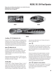
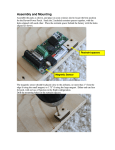
BMC User Manual made in USA READ THIS FIRST There are frequent changes to the camera firmware, it is hard to keep up with them all. Make sure to subscribe to the juicedLink Blog for updated audio applications guides for new camera firmware releases. NOTE JULY 2014: Blackmagic has released new firmware for all of their cameras (4th change to the audio). Earlier, when the camera was not in the hands of many experienced audio users, we provided application guidance on what settings to use in the camera, and EQ settings in post. We are currently booked, and will not have a chance to evaluate the new firmware for quite some time. Today, there are many experienced users on the various forums who can assist with camera settings. Thank you for understanding. METER CALIBRATION: Since every camera has a different sensitivity sweet spot, you will need to calibrate the meter of the BMC388 to the needs of the camera. • BMCC: With the BMCC, you will use Ultrascope. This blog post with firmware v1.3 describes what settings to use in the camera for calibration, and also describes a methodology to fix the camera frequency response in post. The meter calibration section of the Riggy-Assist User Manual describes the procedure for the Riggy-Assist. You will follow a similar procedure with the BMC388, using Ultrascope (instead of the meters of the camera). Note, the BMC388 has eliminated the meter sensitivity switch used on the Riggy-Assist. • BMPC: The BMPC does not have Thunderbolt, so you can not use the meters of Ultrascope for calibration. You will proceed with an iterative test recording to determine the meter calibration. This video from the Riggy-Assist User Manual describes this process (you can ignore the discussion on AGC Disable). For the BMPC, we are using the MIC level gain at 100%. Videos Videos are helpful to illustrate things that are easier to communicate visually. However, these videos do not cover all of the details in their entirety. If you need more detail, then please consult the written User Manual, below. OVERVIEW Watch this video for an overview of the inputs, outputs, signal routing, switchbank, and other features such as phantom power, audio bracketing, and selective power-down. CABLING TO BMCC AUDIO INPUTS made in USA The BMCC inputs are 1/4” phono, and the BMC366 outputs are 3.5mm minijack. Watch this video to see what is necessary to cable up to the BMCC. MOUNTING DIRECTLY TO TOP OF BMCC The BMC366 mounts so nicely directly to the top of the BMCC. It provides a low-profile on the left side, for shoulder mounted situations. It sends the XLR connectors out the right side of the camera (for similar reasons). When mounted, it is as if the preamp is an integral part of your BMCC, like it had XLR connectors right from the start. Watch this video to see how to mount the BMC366 to the top of the BMCC. MOUNTING TO DIY122B BMCC TOP MOUNTING PLATE The DIY122B BMCC Top Mounting Plate provides a cost effective way of mounting lots of accessories to your BMCC. Watch this video to see how to mount the BMC366 to the DIY122B. Quick Start Guide for Single Microphone • METER CALIBRATION: Refer to the “Read this first” section at the top. • MOUNT TO TOP OF BMCC AND CONNECT AUDIO CABLES/ADAPTERS: This process is best communicated visually. Please watch the “Cabling to BMCC Inputs” and “Mounting Directly to Top of BMCC” videos above. • GROUND LOOPS: The previoius mounting/cabling procedure is designed to make sure that the only ground connection between the preamp and the camera is via the audio cables. So, set both Balanced GND OUT and ENC GND switches to the NORM position. • POWER: Insert a fresh 9V alkaline battery into the battery tray in the correct orientation. Set LiPoly/ALK to ALK. Turn L1 PWR and L2 PWR the OFF position since we will not be using the L1 or L2 XLR inputs for a single mic, extending battery life. Remember, you will need to turn L1 PWR or L2 PWR back to the the ON position when you choose to use those channels in the future. • MIC SNR AND MIC PLACEMENT: Low noise preamps are effective at improving poor signal-to-noise of downstream components, like noisy cameras and recorders. However, low-noise preamps can not improve poor signal-to-noise in upstream components. This is to say, garbagein, garbage-out. You will need to use a microphone with decent signal-to-noise characteristics. Additionally, the microphone needs to be placed close to the person speaking (no more than a foot and a half away) for capture of high quality dialogue. made in USA • CONNECT BALANCED MIC: Connect a balanced XLR microphone into the R XLR input. For simple dialog, set MIC/LINE to MIC and GAIN on HI for the R channel. Apply Phantom Power to the R channel if necessary. See the WARNINGS - Phantom Power section at the end of this document. • UNBALANCED MIC: For minijack mics which are unbalanced, use a Rode VXLR adapter to connect to the balanced XLR inputs of the preamp. Note, if the miniplug pinout on your unbalanced mic is nonstandard, the Rode VXLR may short out the mic output and no signal will make it to the preamp, so you will need to find a different adapter solution. Never apply phantom power to unbalanced mics, and see the WARNINGS - Phantom Power section at the end of this document. • SIGNAL ROUTING TO OUTPUT: Since this setup only uses one mic, set MONO/STEREO to MONO. This will mix all of the mic inputs together, and route them all to both the right and left outputs. If you wish to have channel separation when you are using more than one mic, then set to STEREO, and L1 and L2 will be routed to the left output channel, and R will be routed to the right. • CAMERA OVERLOAD PROTECTION: You may wish to use Audio Bracketing for camera overload protection, indicated by the GREEN switch settings. This mixes all of the microphones together (MONO setting), and attenuates the right output by about 16dB (R OUT -16dB PAD set to ON). So, if you blow out your main channel (left) you have a backup recording on the right at a safe lower level that you can pull from in post. This approach has advantages over other types of overload protection, such as limiters. First, Audio Output Bracketing consumes no power from the battery, and also adds no noise or distortion to your audio. Second, every camera gain setting (and, every different camera) will have a unique signal level at which clipping will start to occur. So, if you were to attempt to use a limiter approach, you would need to recalibrate the point at which the limiter would kick in for each different gain setting of the camera (and, each different camera). • CAMERA SETTING FOR SIGNAL-TO-NOISE: The BMCC firmware remains a work in progress. Please make sure you are subscribed to the juicedLink blog. Here is our latest blog post related to BMCC camera settings. • SIGNAL LEVEL ADJUSTMENT / METERING: Adjust the front panel potentiometer volume control for XLR-L so the audio peaks splash up to -12dB on the meter of the camera. • HEADPHONES: Plug headphones the camera’s headphone output. More Details • • Explanation of Switches made in USA o ENC GND: The NORM position connects analog ground to the enclosure. The LIFT position disconnects the enclosure from analog ground. See the “Mounting, Grounding, Ground Loops, and the ENC GND Switch” section below for more details. o Balanced GND Out: The NORM position connects analog ground to the minijack output cable shield ground. The LIFT position breaks that connection. See the “Mounting, Grounding, Ground Loops, and Ground Switches” section below for more details. o MIC/LINE: LINE inserts a 40dB pad at the XLR input before the preamp circuit. o GAIN - HI/LO: The preamp is typically used in the HI gain position. LO gain is used when in a high signal level environment, like a rock concert or the tarmac of an airport. o PHANTOM - OFF/12V/48V: This controls the switching power supply of the phantom voltage generating circuit. o PHANTOM - XX > ON: The ON position routes the voltage from the phantom voltage generating circuit to the corresponding XX XLR input. See the WARNINGS - Phantom Power section of this document. o L1 PWR and L2 PWR - ON/OFF: Powers on/off the preamps for the L2 and R XLR inputs. o STEREO/MONO: MONO mixes all XLR inputs together, and presents them all to both the right and left outputs. STEREO routes XLR-R to the right output, and XLR-L1 and XLR-L2 to the left output. o R OUT -16dB PAD - ON/OFF: This engages an approximately 16dB attenuator in the right output channel. It is used in conjunction with the MONO setting (the GREEN switch settings) to achieve Audio Output Bracketing for camera overload protection. o LiPoly/ALK: ALK sets the low battery threshold suitable for alkaline batteries. LiPoly sets the low battery threshold suitable for LithiumPolymer batteries. Mounting the Preamp o Mounting, Grounding, Ground Loops, and the Ground Switches Ground Loops can result in a hum/buzz in your audio, made in USA and are created when multiple ground paths between pieces of equipment exist. You will always have one ground connection between the preamp and your camera, and that is via the shield in the stereo minijack cable that goes from the MIC OUT of the preamp into the MIC IN of the camera. However, depending on how/where you mount the preamp, a second ground connection can be created between the preamp enclosure and camera enclosure. The preamp enclosure is black anodized, which is non conductive. So, any elements in contact with the black anodized portion of the enclosure are not in contact with the enclosure ground Any silver parts of the enclosure, such as the female 1/4-20 tripod mounting hole, are electrically connected to the enclosure. So, any components in contact with these elements are also in contact with the enclosure ground. The camera mounting screw that goes through the preamp is suspended by nylon shoulder washers, so it is not in contact with the enclosure ground In the NORM position of the ENC GND switch, the enclosure ground is connected to the ground of the circuitry inside the preamp. So, if the camera enclosure finds a path to the preamp enclosure, you will have a ground loop. The NORM switch position is what is typically used when the preamp is mounted to the bottom of the camera, and there is only one ground connection between the preamp and the camera via the shield of the stereo minijack cable. There is no ground connection between the enclosure of the preamp to the enclosure of the camera, since the camera mounting screw that goes through the preamp and is in contact with enclosure of the camera, but the camera mounting screw that goes through the preamp is electrically isolated from the preamp enclosure via the nylon shoulder washers. In the LIFT position of the ENC GND switch, the circuitry inside the preamp is electrically isolated from the ground of the enclosure. o So, if the camera enclosure finds a path to the preamp enclosure, you will LIFT the ground to the preamp enclosure to eliminate the ground loop. A potential path could be where your camera is mounted to a rig, and the preamp is mounted to the same rig via the silver female 1/4-20 tripod mounting hole on the bottom of the preamp. However, if you LIFT the enclosure ground from the circuitry of the preamp when there is no ground connection between the camera enclosure and the preamp enclosure, then you will be disabling phantom power. This is because the XLR connector pulls its ground from the preamp enclosure, so the XLR connector needs to get the ground reference from the enclosure of the camera when in the LIFT position. Additionally, if you disconnect the stereo minijack cable between the MIC OUT of the preamp to the MIC IN of the camera, you will also be disabling the phantom when in the LIFT position. This process is best communicated visually. Please see the “Mounting Directly to Top of BMCC” video, above. Audio Connection Between Preamp and Camera o • Mounting to the top of your BMCC • made in USA Please see the “Cabling to BMCC Audio Inputs” video, above. Powering o A 9V battery must be placed in the battery tray in accordance with the polarity markings found at the bottom of the battery tray. o Different battery chemistries will have different drop out voltages. The low battery threshold indicator is calibrated for both alkaline and lithium-polymer (rechargable) batteries. Select the appropriate switch setting for ALK/LiPoly for the battery type used. o Preamps are high-current devices, unlike other things like smoke detectors, etc. So, they require that the batteries used are fresh. Please note that it is possible to get bad packs of batteries from the store. Weakened batteries have a buildup of their internal resistance. The larger this resistance becomes, the more made in USA of a voltage drop that will occur when supplying large currents, thus triggering the low battery indicator. o • Maximizing power efficiency: Phantom power sucks a lot of current from the battery. Whenever it is not needed, make sure that phantom power is off. Whenever you have the option to run a mic from its own battery or phantom power, run it from its own battery and keep phantom power off (or, do not route phantom power to that mic, if you are required to have phantom power on to power another mic that is connected). It is often desirable to use a mic that works from phantom power only, since that mic can be much smaller and lighter without the battery compartment. When you are in the market for a new mic, many modern mics will work down to 12V phantom, so consider one of those mics. It consumes much less power to run from 12V instead of 48V. The preamp has the ability to power down unused XLR inputs, via the L1 PWR and L2 PWR switch. Power off when those inputs are not in use, and this will extend battery life considerably. Connecting to the Preamp Inputs o The preamp inputs are balanced XLR, where pin-2 is HOT, pin-3 is COLD, and pin-1 is GND. So, balanced XLR microphones will directly interface using the MIC setting. The output of balanced mixers will interface directly as well, and you may need to engage the 40dB attenuator at the input by using the LINE setting. o Unbalanced sources (minijack mics, wireless mics) can interface to balanced inputs. You will need to use a connector that connects pin-3 COLD to pin-1 GND. For example, the Rode VXLR connector provides such functionality going from minijack to XLR. Never apply phantom power to unbalanced sources. See the WARNINGS Phantom Power section at the end of this document. Note, the VXLR will not work with mics which have a miniplug with a nonstandard pinout. o Phantom Power Condenser-type microphones require power. Some microphones can be powered by their own internal battery. Other microphones require power to be sourced by the equipment that the mic is being plugged into, and made in USA transmitted up the mic cable from the mixer to the mic. This is known as phantom power. • • PHANTOM - OFF/12V/48V: This controls the switching power supply of the phantom voltage generating circuit. Check your microphone user manual for its powering requirements. Select the lowest phantom setting that is required by all mics being used. PHANTOM - XX > ON: The ON position routes the voltage from the phantom voltage generating circuit to the corresponding XX XLR input. IMPORTANT. See the WARNINGS - Phantom Power section at the end of this document. Phantom power sucks a lot of current from the battery. Whenever it is not needed, make sure that phantom power is off. Whenever you have the option to run a mic from its own battery or phantom power, run it from its own battery and keep phantom power off (or, do not route phantom power to that mic, if you are required to have phantom power on to power another mic that is connected). It is often desirable to use a mic that works from phantom power only, since that mic can be much smaller and lighter without the battery compartment. When you are in the market for a new mic, many modern mics will work down to 12V phantom, so consider one of those mics. It consumes much less power to run from 12V instead of 48V. Signal Level Controls for each XLR Channel o Signal level control is accomplished via MIC/ LINE switch, GAIN switch, and volume control potentiometer (on the front panel. For typical use with a microphone recording simple dialogue, you will have MIC/LINE set to MIC, GAIN set to HI, and you will adjust the volume control potentiometer so the peaks splash just splash up to the -12dB on the meter of the camera. o The LO GAIN setting is used for very high signal level environments, like a rock concert or the tarmac of an airport, to provide more headroom in the preamp. Routing Preamp Intputs to Camera o MONO mixes all XLR inputs together, and presents them all to both the right and left outputs. STEREO routes XLR-R to the right made in USA output, and XLR-L1 and XLR-L2 to the left output. • Meter Calibration o • • See the “Read this first” section at the top. Achieving the Best Signal-to-Noise o The BMCC firmware is still a work in progress. Please see make sure you subscribe to the juicedLink blog. Please see our blog post regarding how to work with the current version of the BMCC firmware. o Turn down the potentiometer volume controls all of the way for any unused XLR input. o Limitations in Signal-to-Noise: Low noise preamps are effective at improving poor signal-to-noise of downstream components, like noisy cameras and recorders. However, low-noise preamps can not improve poor signal-to-noise in upstream components. This is to say, garbage-in, garbage-out. You will need to use a microphone with decent signal-to-noise characteristics. Additionally, the microphone needs to be placed close to the person speaking (no more than a foot and a half away) for capture of high quality dialogue. Achieving the Widest Dynamic Range o Audio Output Bracketing You may wish to use Audio Bracketing for camera overload protection, indicated by the GREEN switch settings. This mixes all of the microphones together (MONO), and attenuates the right output by about 16dB (R OUT -16dB PAD - ON). So, if you blow out your main channel (left) you have a backup recording on the right at a safe lower level that you can pull from in post. This can be used with any camera. You can change gain settings in the camera with no problem. You can even combine it with the camera’s AUTO setting for even further extended dynamic range This approach has advantages over other types of overload protection, such as limiters in preamps. First, Audio Output Bracketing consumes no power from the battery, and also adds no noise or distortion to your audio. Second, every camera gain setting (and, every different camera) will have a unique signal level at which clipping will start to made in USA occur. So, if you were to attempt to use a limiter approach, you would need to re-calibrate the point at which the limiter would kick in for each different gain setting of the camera (and, each different camera). • WARNINGS: o Phantom Power: NEVER apply phantom power to anything other than a mic which requires it, otherwise you are basically shorting 48V to ground and risk damaging your equipment. Check your microphone user manual for its requirements. When the phantom power gets shorted, it sucks a huge amount of current from the battery (so, your battery life will be awful). Plus, the phantom power IC will get extremely hot. After a period of time, it may not be able to handle it and burn out. Plus, whatever you are applying phantom power to can get damaged (such as mixers and ribbon mics). Never apply phantom power to: 1) wireless mic receivers, 2) any unbalanced mic, 3) ribbon mics, 4) dynamic mics, 5) mixers, 6) condenser mics already being powered by their own internal battery. o Risk of Hearing Loss: During production, you will be using headphones for monitoring audio. Headphone amplifiers are capable of driving signal levels which are damaging to hearing. Protect your hearing. Start with the volume at a low level, and use at the lowest practical signal level. Don’t wear headphones when plugging headphones into headphone amps, when powering on/off your equipment, when plugging external equipment into your mixer (mics, mixers), when powering on phantom power. o Risk of Electric Shock: The enclosure is electrically conductive and electrically connected to the shields of the mic cables plugged into the mixer. Avoid electrocution and observe caution with cable runs in areas where high voltages and/or currents exist.