1
P
Programming Manual
Programming Manual
MX Component Version 2 Programming Manual
MODEL
MELS2-ACTE-P-E
MODEL
CODE
13JF65
SH(NA)-080155-A(0104)MEE
HEAD OFFICE : MITSUBISHI DENKI BLDG MARUNOUCHI TOKYO 100-8310 TELEX : J24532 CABLE MELCO TOKYO
NAGOYA WORKS : 1-14 , YADA-MINAMI 5 , HIGASHI-KU, NAGOYA , JAPAN
When exported from Japan, this manual does not require application to the
Ministry of Economy, Trade and Industry for service transaction permission.
Specifications subject to change without notice.
SW2D5C-ACT-E
• SAFETY PRECAUTIONS •
(Always read these instructions before using this equipment.)
Before using this product, please read this manual and the relevant manuals introduced in this manual
carefully and pay full attention to safety to handle the product correctly.
The instructions given in this manual are concerned with this product. For the safety instructions of the
programmable controller system, please read the CPU module user's manual.
In this manual, the safety instructions are ranked as "DANGER" and "CAUTION".
DANGER
Indicates that incorrect handling may cause hazardous conditions,
resulting in death or severe injury.
! CAUTION
Indicates that incorrect handling may cause hazardous conditions,
resulting in medium or slight personal injury or physical damage.
!
Note that the ! CAUTION level may lead to a serious consequence according to the circumstances.
Always follow the instructions of both levels because they are important to personal safety.
Please save this manual to make it accessible when required and always forward it to the end user.
[Design Instructions]
!
DANGER
• When performing data changes or status control from the personal computer to the running
PLC, configure up an interlock circuit outside the PLC system to ensure that the whole system
will operate safely.
In addition, predetermine corrective actions for the system so that you can take measures
against any communication error caused by a cable connection fault or the like in online
operations performed from the peripheral device to the PLC.
!
CAUTION
• Read the manual carefully before performing the online operations (especially forced output and
operating status change) which will be executed with the personal computer connected to the
running CPU module.
Not doing so can damage the machine or cause an accident due to misoperation.
A-1
A-1
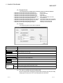
REVISIONS
* The manual number is given on the bottom left of the back cover.
Print Date
Mar., 2001
* Manual Number
SH (NA)-080155-A First edition
Revision
Japanese Manual Version SH-080152-A
This manual confers no industrial property rights or any rights of any other kind, nor does it confer any patent
licenses. Mitsubishi Electric Corporation cannot be held responsible for any problems involving industrial property
rights which may occur as a result of using the contents noted in this manual.
2001 MITSUBISHI ELECTRIC CORPORATION
A-2
A-2
Operating Instructions
(1) When using Microsoft Windows NT Workstation Operating System Version 4.0
and Microsoft Windows 2000 Professional Operating System
When using Windows NT Workstation 4.0 and Windows 2000 Professional,
MX Component may be installed and used only on the administrator's authority.
R
R
R
R
R
R
(2) About Ethernet communication, computer link communication and CPU COM
communication on Microsoft Windows 95 Operating System
(a) Making Ethernet communication using TCP/IP and UDP/IP on Windows 95
of the version older than OSR2 will cause a memory leak. When performing
continuous operation on Windows 95, use Window 95 OSR2 or later.
(b) On Windows 95, communication using the COM port, e.g. computer link
communication or CPU COM communication, will cause a memory leak.
Therefore, do not perform continuous operation.
R
R
R
R
R
R
(3) About installation
(a) When performing overwrite installation, install the software in the folder
where it had already been installed.
(b) If you install the MELSEC board driver or GX Developer into the personal
computer where MX Component has already been installed, communication
using a specific path (e.g. ASCII packet of the AJ71E71) may result in a
receive, device number or other error.
If any of these phenomena has occurred, perform overwrite installation of MX
Component again.
(4) Precautions for performing installation and uninstallation on a dual boot machine
where two different operating systems are installed in a single IBM-PC/AT
compatible personal computer
On a dual boot machine having Windows NT Workstation 4.0 (hereafter referred to
as OS1) and Windows 95/98 (hereafter referred to as OS2), note the following points
when MX Component was installed on OS1 first and MX Component was then
installed over the same folder on OS2.
(a) If MX Component is uninstalled first on the OS2 side, uninstallation does not
delete the control DLLs and ACT folders, and they remain within the IBMPC/AT compatible.
To delete the control DLLs and ACT folders, perform uninstallation also on
the OS1 side.
R
R
(b) If MX Component is uninstalled first on the OS1 side, the control DLLs and ACT
folders are deleted.
In this case, MX Component may not operate properly or cannot be uninstalled on
the OS2 side.
Install MX Component again on the OS2 side to operate MX Component properly or
uninstall it on the OS2 side.
(5) About start menu
When you have uninstalled MX Component, the item may remain in the start
menu.
In that case, restart the IBM-PC/AT compatible personal computer.
A-3
A-3
(6) About the resume and other functions of personal computer
A communications error may occur if communications are made with the PLC
CPU after setting the resume function, suspend setting, power-saving function
and/or standby mode of the personal computer.
Therefore, do not set the above functions when making communications with the
PLC CPU.
(7) About transmission speed
As the transmission speed of the QCPU(Q mode) and QCPU(A mode), you can
set 9600bps, 19200bps, 38400bps, 57600bps or 11520bps.
For the QnACPU of version 9707B or later, you can set the transmission speed
of 9600bps, 19200bps or 38400bps.
For the QnACPU of other versions, you can set 9600bps or 19200bps.
The transmission speeds of the ACPU (except A2USHCPU-S1), FXCPU and
motion controller CPU are fixed to 9600bps. (The A2USHCPU-S1 may be set to
19200bps.)
(8) About use of the Q4ARCPU
(a) When using the UDP/IP protocol of Ethernet communication, use the
Q4ARCPU whose year and month of manufacture is "0012" or later and the
QE71 whose function version is B or later.
(b) The duplexing function cannot be used.
(9) Restrictions on use of the FXCPU
(a) For the index registers (Z, V) of the FXCPU, data cannot be written to 2 or
more consecutive points using WriteDeviceBlock(). (Data may be written to
only one point.)
(b) When the FXCPU is used, access to the TN devices (timer present values)
or CN devices (counter present values) is not permitted if the device numbers
specified are split across 199 or earlier and 200 or later.
(10) About clock data of the PLC CPU
(a) For the ACPU (including the motion controller CPU), clock data setting may
be made only when the PLC CPU is in the STOP status.
For the QCPU (Q mode), QCPU (A mode), QnACPU and FXCPU, clock data
setting may be made if the PLC CPU is in the RUN status.
(b) For the A0J2HCPU, A2CCPU and A2CJCPU, setting cannot be made as
they do not have the clock function.
(c) For the ACPU, setting can be made independently of whether the clock
setting special relay "M9028" is ON or OFF. (Note that the special relay
"M9028" turns OFF after execution.)
For the QCPU (Q mode), QCPU (A mode) and QnACPU, setting can be
made independently of whether the clock setting device "SM1028" is ON or
OFF.
(d) Among the FXCPUs, setting may be made for only the FX1N (clock built-in),
FX1NC (clock built-in), FX1S (clock built-in), FX2N (clock built-in), FX2NC (clock
built-in), FX2 (when RTC cassette is fitted) and FX2C (when RTC cassette is
fitted).
(e) Note that an error for transfer time will be produced in clock setting.
A-4
A-4
(11) About simultaneous use of MX Component and GX Developer
When using GX Developer and MX Component together for the same E71
module to make Ethernet communication, make the following settings.
(a) Set the protocol of the communication setting wizard screen to "UDP/IP".
(b) Set "SW2" of the communications setting switches of the E71 module to OFF
(binary).
(12) Simultaneous access when using Q series-compatible Ethernet module
The following conditions should be satisfied when communication is to be made
simultaneously from multiple IBM-PC/AT compatibles to the same module using
the TCP/IP protocol.
• The Q series-compatible Ethernet module is of function version B or later.
• Using GX Developer Version 6.05F or later, set "MELSOFT connection" in the
Ethernet parameter "open system".
(13) About target existence check starting interval 1 of Ethernet module
If close processing (Close) is executed from the IBM-PC/AT compatible, the Ethernet
module may not perform close processing (Close).
One of its causes is the open cable.
If open processing (Open) is executed from the IBM-PC/AT compatible with the
Ethernet module not performing close processing (Close), open processing (Open)
from the IBM-PC/AT compatible is not terminated normally until the Ethernet module
makes a target existence check and executes close processing (Close).
If you want to terminate open processing (Open) early from the IBM-PC/AT
compatible, shorten the target existence check starting interval setting of the Ethernet
module.
(The target existence check starting interval setting of the Ethernet module defaults to
10 minutes.)
1: It can be set for the E71 of AJ71E71-S3 or later.
(14) Replacement of Ethernet module
If you changed the Ethernet module during Ethernet communication due to
debugging, failure or like, the other node (IBM-PC/AT compatible) must be
restarted.
(Since the Ethernet addresses (MAC addresses) differ between devices)
(15) Software version of CC-Link master/local module
As the CC-Link master/local module used in CC-Link communication or CC-Link
G4 communication(only when the AJ65BT-G4 is used), use the module of
software version "N" or later.
The module of software version "M" or earlier will not operate properly.
(16) Software version of CC-Link G4 module
As the CC-Link G4 module used in CC-Link G4 communication(only when the
AJ65BT-G4 is used), use the module of software version "D" or later.
The module of software version "C" or earlier will not operate properly.
(17) About relaying from the MELSECNET/10 loaded station
When the module is loaded to the AnNCPU or AnACPU, it is recognized as a
MELSECNET(II) module.
When the connected station is the AnNCPU or AnACPU, set the relayed
network as MELSECNET(II).
In addition, set the station number to "0" when making access to the control
station.
A-5
A-5
(18) About computer link communication
(a) If the connected station CPU is the AnUCPU and the computer link module is
the UC24 for computer link connection, remote operation will result in an
error when access is made to the AnNCPU, AnACPU or QnACPU via the
MELSECNET/10.
(b) On any computer link modules other than the UC24 and C24, remote
"PAUSE" operation will result in an error for all connections.
(c) For the QC24, note that the illegal case of specifying the first I/O number of a
nonexisting module and reading/writing U
\G
will not return an error if
the software version of the module is "k" or earlier.
(d) In any connection form (direct coupling, relaying) where the target station of
the UC24 or C24 is the QnACPU, an error is returned if clock data read/write
is executed.
(19) Precautions for USB communication
Frequently disconnecting/reconnecting the USB cable or resetting or powering
ON/OFF the PLC CPU during communications with the PLC CPU may cause a
communications error which cannot be recovered.
If it is not recovered, completely disconnect the USB cable once and then
reconnect it after 5 or more seconds have elapsed.
(If this error occurs at the initial communication after the above operation, the
function will be performed properly in and after the second communications.)
(20) Precautions for GX Simulator communication
Before executing the monitor utility, communication setting utility or user
program, make sure that GX Simulator and GX Developer are operating.
In addition, do not terminate the GX Simulator and GX Developer while the user
program is running.
If you do so, you will not be able to terminate the user program normally.
(21) About forced termination of processes during communication
If communication is being made with the same type of control open for multiple
processes, forcing one process to be terminated by Task Manager or the like
may stop the other processes at the communication function execution area.
(22) About sample programs, test programs and sample sequence programs
(a) Sample programs, test programs
The sample programs are attached for your reference to create user
programs.
The test programs are attached to conduct communication tests.
Use these programs on your own responsibility.
(b) Sample sequence programs
The sample sequence programs attached to MX Component assume that
only an IBM-PC/AT compatible personal computer and Ethernet modules
exist in the network.
Depending on your system configuration and parameter settings, the
programs must be modified. Make corrections to make the programs
optimum for your system.
Also, use the sample sequence programs on your own responsibility.
A-6
A-6
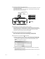
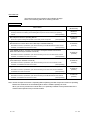
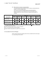
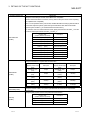
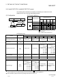
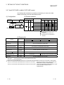
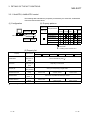
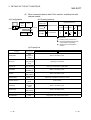
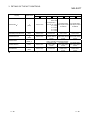
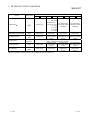
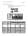
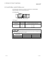
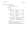
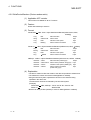
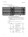
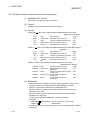
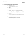
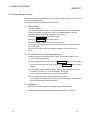
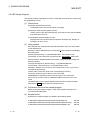
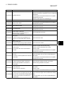
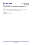
(23) Unlocking password when using QJ71E71
The range where the password can be unlocked by remote operation is up to the
connection target station.
If the password is set also on the lower layer, communication cannot be made
with the PLC CPU on the lower layer.
Starting
source
Enter password to
unlock.
AAAA
No.
1)
2)
3)
4)
5)
Ethernet
QCPU 1)
2)
(Q
QJ71 QJ71
mode) E71 E71
Ethernet
QCPU 3)
(Q
QJ71
mode) E71
QCPU 4)
(Q
QJ71
mode) E71
QCPU 5)
(Q
QJ71
mode) E71
Remote Password
With setting (AAAA)
Without setting
With setting (AAAA)
With setting (BBBB)
Without setting
: Accessible
: Inaccessible
1) Unlocking QJ71E71 password enables
access to PLC CPUs in this range.
(24) Resetting PLC CPU during TCP/IP connection setting
If you reset the PLC CPU during TCP/IP connection setting (during opening)
using MX Component, a communication or receive error will occur at the time of
communication after that. In that case, close the application that uses MX
Component and then perform open processing again.
(25) Security of the Internet/intranet when using VBScript
MX Component does not have the Internet/intranet security function.
When you need the security function, make setting on the user side.
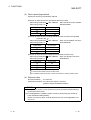
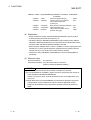
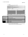
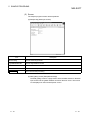
(26) Precautions for use of Microsoft Access 2000
R
(a) When you paste the ACT control to an Access 2000 form and double-click
the ACT control or choose the custom control in the property, the following
error message will appear but this does not affect the operation of ACT
control.
(Other error message may appear.)
(b) When you paste the ACT control and display the properties, the property
names displayed may be broken.
As this phenomenon occurs for only the property indication, there will be no
problem in the property functions.
A-7
A-7
(27) Precautions for use of Microsoft Excel 2000
(a) If you paste the control to Excel 2000, it may sometimes not be pasted.
This phenomenon occurs if the cache file (temporary file) of Excel 2000
remains.
In such a case, perform operation in the following procedure.
1) Close Excel 2000.
2) Delete *.exd in the Excel 8.0 folder of the temp folders.
3) Restart Excel 2000.
(b) The size of the ACT control can be changed but this does not affect the
operation of MX Component.
To restore the size, set the Height and Width properties of ACT control to
"24" again.
R
(28) Precautions for use of Microsoft Windows Millennium Edition Operating
System
It is not recommended to use MX Component with the "system restoring
function" made invalid by the operating system.
If the free space of the system drive becomes less than 200MB, the "system
restoring function" is made invalid by the operating system. When using
Windows Me, reserve a 200MB or more free space for the system drive.
R
R
R
(29) About error at communication start
A communication error may occur within the preset time-out period at a
communication start, e.g. when the communication diagnostic button is pressed,
at a monitor start, or at the execution of any function.
These errors are assumed to be detected before a time-out error.
(Example: Connection cable not connected, at PLC power-off)
(30) About Ethernet communication
(a) When access is made to the QnACPU, AnUCPU, QCPU (A mode) or motion
controller CPU via the E71, the device range is equivalent to that of the
AnACPU.
(b) When making access to the PLC CPU through Ethernet communication, the
functions may not be executed depending on the PLC CPU status.
1) When the protocol is TCP/IP (target module: E71, QE71)
The functions can be executed only when the communication target PLC
CPU is in the RUN mode.
An error is returned if the PLC CPU is in other than the RUN mode.
2) When the protocol is UDP/IP (target module: E71, QE71)
The functions cannot be executed until the communication target PLC
CPU is RUN once.
An error is returned if the PLC CPU has not been RUN once.
(c) The communication line is broken if the CPU becomes faulty or the Ethernet
module is reset during Ethernet communication (when the protocol is
TCP/IP).
In that case, perform line close processing (Close) and then execute reopen
processing (Open).
A-8
A-8
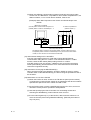
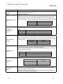
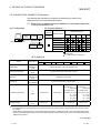
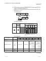
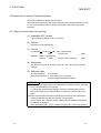
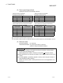
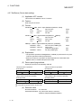
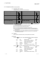
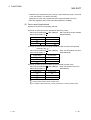
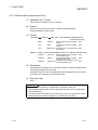
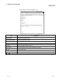
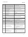
(d) When two different communication systems (protocols) are used to make
access from one IBM-PC/AT compatible to one Q series-compatible E71, two
station numbers, i.e. for TCP/IP and for UDP/IP, must be set.
(Example) When MX Component uses TCP/IP and GX Developer uses
UDP/IP
IBM-PC/AT compatible
(TCP/IP) station number for MX Component: 2
(UDP/IP) station number for GX Developer : 3
Q series-compatible E71
(Station number: 1)
GX Developer(UDP/IP)
MX Component(TCP/IP)
Set different station numbers as the (TCP/IP) station number for MX Component
and (UDP/IP) station number for GX Developer. If they are set to the same station
number, an error will occur on the Ethernet module side.
(31) About switch settings of E71 and QE71
If the four lower digits of the error code that occurred during Ethernet
communication using the E71 or QE71 is not indicated in the E71 or QE71
manual, check the DIP switch (SW2) setting of the E71 or QE71.
If the DIP switch is not set correctly, a difference has occurred in the packet
format (ASCII/binary) and therefore the error code returned from the module
cannot be recognized correctly.
(32) Instructions for relaying the MELSECNET(II)
When access is made to the QnACPU, AnUCPU, QCPU (A mode) or motion
controller CPU via the MELSECNET(II), the device range is equivalent to that of
the AnACPU.
(33) Restrictions on use of the FXCPU
(a) When the FXCPU is used, access to the TN devices (timer present values)
or CN devices (counter present values) is not permitted if the device numbers
specified are split across 199 or earlier and 200 or later.
(b) As the FXCPU does not have a PAUSE switch as the PLC CPU, an error is
returned if remote pause is specified in SetCpuStatus.
(c) Note that specifying the first I/O number of a nonexisting module and
executing the WriteBuffer( ) method will not return an error.
(d) For the index registers (Z, V) of the FXCPU, data cannot be written to 2 or
more consecutive points using WriteDeviceBlock(). (Data may be written to
only one point.)
A-9
A-9
(34) CheckDeviceString
Do not use the CheckDeviceString method of each ACT control.
(35) About ActUMsg control, ActUWzd control, ActMnet2BD control and ActAFBD
control
Installing MX Component registers the ActUMsg control, ActUWzd control,
ActMnet2BD control and ActAFBD control, but do not use them.
(36) Precautions for use of Act(ML)QJ71E71TCP, Act(ML)AJ71QE71TCP and
Act(ML)AJ71E71TCP controls
(a) Provide an interval longer than the sequence scan time of the Ethernet
module loaded station from when the Open method is executed until the
Close method is executed.
(b) Provide an interval of at least 500ms from when the Close method is
executed until the Open method is executed again.
(37) Precautions for use of EXCEL VBA
Do not set the page feed preview function in the application that uses EXCEL
VBA.
Doing so can cause a memory leak or OS basic operation (file operation,
printing or other) fault.
(38) Serial communication function of Q00J/Q00/Q01CPU
When the following conditions are all satisfied, communication between the
personal computer and the Q00J/Q00/Q01CPU is made at 9600bps speed.
1) The connected CPU is the Q00CPU or Q01CPU
2) The serial communication function of the connected CPU is valid.
3) The personal computer side baud rate setting differs from the
Q00J/Q00/Q01CPU side baud rate setting.
To increase the communication speed, match the personal computer side baud
rate with the Q00J/Q00/Q01CPU side baud rate.
(39) Precautions for starting multiple Excel files on Windows Me
Note that Windows Me has been confirmed to stop if you run multiple Excel
files which use many control objects.
This phenomenon is not attributable to this product.
(a) Conditions on which this phenomenon has been confirmed to occur
Graphic driver
: Matrox make MGA Mystique display driver
OS
: Windows Me (English version)
Number of controls pasted to Excel files : A total of 150 or more controls
used in the whole BOOK
<Other devices checked by Mitsubishi (reference)>
CPU
: Pentium 166MHz
Memory : 64MB
Hard disk : 8GB (free space 6GB)
R
R
R
R
A - 10
A - 10
(b) Cause
The phenomenon has been confirmed to occur when the Matrox make MGA
Mystique graphic card display driver is used.
This is because Version 4.12 of the MGA Mystique graphic card display
driver is not compatible with Windows Me.
R
(c) How to judge whether the phenomenon is the same or not
After changing the used graphic driver for the standard VGA driver, delete the
temporary data (*.emf) left in the temporary folder.
After that, try starting multiple Excel files.
The phenomenon seems to be the same if it does not occur by changing the
driver for the standard VGA driver.
(d) Corrective action
If this phenomenon occurs, the temporary data (*.emf) will be left in the
temporary folder of the system.
You have to delete the remaining temporary data (*.emf) manually.
The temporary folder of the system is normally in C:\Temp.
After that, take either of the following actions.
1) Use the graphic card and display driver which support Windows Me.
2) Reduce the number of control objects pasted to the Excel files.
R
(40) Precautions for COM communication or TCP/IP communication on ASP page
and application 1
If the ASP page opens COM or TCP/IP communication earlier than the
application, communication in the same path cannot be made on the application
until the ASP page is closed. Therefore, note the following points.
(a) COM or TCP/IP communication should be opened on the application earlier.
After it has been opened on the application, communication can be made on
both the application and ASP page until it is closed.
(b) When COM or TCP/IP communication has been opened on the ASP page,
always close the communication.
1 The application indicates any of the user applications created using the
MX series and MELSOFT products.
(41) Precautions for connecting personal computer and serial communication
module
(a) When QJ71C24-R2 of function version A is used
An MX Component application can use only either of CH1 and CH2.
When the MELSOFT product, such as GX Developer or GOT, is using one
channel, the application cannot use the other channel.
When the QJ71C24-R2 of function version B is used, the application can use
both channels.
(b) When AJ71QC24-R2 or A1SJ71QC4-R2 is used
The MX Component application can use only CH1.
It cannot use CH2.
A - 11
A - 11
INTRODUCTION
Thank you for choosing the Mitsubishi MELSOFT series comprehensive Factory Automation software.
Read this manual and make sure you understand the functions and performance of MELSOFT series
thoroughly in advance to ensure correct use.
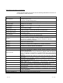
CONTENTS
SAFETY PRECAUTIONS..............................................................................................................................A- 1
REVISIONS ....................................................................................................................................................A- 2
Operating Instructions ....................................................................................................................................A- 3
CONTENTS....................................................................................................................................................A-12
About Manuals ...............................................................................................................................................A-15
How to Use This Manual................................................................................................................................A-16
Abbreviations and Terms in This Manual......................................................................................................A-17
1 OVERVIEW
1- 1 to 1- 3
1.1 Outline of ACT controls............................................................................................................................ 11.2 ACT control and Function Lists ............................................................................................................... 11.2.1 ACT control list .................................................................................................................................. 11.2.2 Function list........................................................................................................................................ 12 ABOUT THE ACT CONTROLS
1
2
2
3
2- 1 to 2-16
2.1 Settings Made for Use of the ACT controls............................................................................................. 2- 1
2.1.1 When using Microsoft Visual Basic 6.0......................................................................................... 2- 1
2.1.2 When using Microsoft Visual C++ 6.0........................................................................................... 2- 3
2.1.3 When using VBA ............................................................................................................................... 2- 7
2.1.4 When using VBScript ........................................................................................................................ 2- 9
2.2 Programming Procedures........................................................................................................................ 2-10
2.2.1 When using Visual Basic ................................................................................................................ 2-10
2.2.2 When using Visual C++ .................................................................................................................. 2-11
2.2.3 When using VBA ............................................................................................................................... 2-12
2.2.4 When using VBScript ........................................................................................................................ 2-13
2.3 Device Types............................................................................................................................................ 2-14
2.4 Accessible Devices and Ranges ............................................................................................................. 2-16
R
R
R
R
R
R
3 DETAILS OF THE ACT CONTROLS
3- 1 to 3-54
3.1 Details of the ACT Controls ..................................................................................................................... 3- 1
3.2 Details of the Properties........................................................................................................................... 3- 2
3.3 Lists of Properties Possessed by the ACT Controls ............................................................................... 3- 7
3.3.1 ActEasyIF, ActMLEasyIF control ...................................................................................................... 3- 8
3.3.2 ActQJ71E71TCP, ActMLQJ71E71TCP control ............................................................................... 3- 9
3.3.3 ActQJ71E71UDP, ActMLQJ71E71UDP control .............................................................................. 3-11
3.3.4 ActAJ71QE71TCP, ActMLAJ71QE71TCP control .......................................................................... 3-13
3.3.5 ActAJ71QE71UDP, ActMLAJ71QE71UDP control ......................................................................... 3-14
3.3.6 ActAJ71E71TCP, ActMLAJ71E71TCP control ................................................................................ 3-15
A - 12
A - 12
3.3.7 ActAJ71E71UDP, ActMLAJ71E71UDP control ............................................................................... 3-16
3.3.8 ActQCPUQ, ActMLQCPUQ control.................................................................................................. 3-17
3.3.9 ActQCPUA, ActMLQCPUA control................................................................................................... 3-19
3.3.10 ActQnACPU, ActMLQnACPU control ............................................................................................ 3-20
3.3.11 ActACPU, ActMLACPU control ...................................................................................................... 3-21
3.3.12 ActFXCPU, ActMLFXCPU control.................................................................................................. 3-22
3.3.13 ActQJ71C24, ActMLQJ71C24 control............................................................................................ 3-23
3.3.14 ActAJ71QC24, ActMLAJ71QC24 control....................................................................................... 3-27
3.3.15 ActAJ71UC24, ActMLAJ71UC24 control ....................................................................................... 3-29
3.3.16 ActAJ71C24, ActMLAJ71C24 control............................................................................................. 3-31
3.3.17 ActQCPUQUSB, ActMLQCPUQUSB control ................................................................................ 3-33
3.3.18 ActCCG4QnA, ActMLCCG4QnA control ....................................................................................... 3-35
3.3.19 ActCCG4A, ActMLCCG4A control ................................................................................................. 3-36
3.3.20 ActMnet10BD, ActMLMnet10BD control ........................................................................................ 3-37
3.3.21 ActMnetHBD, ActMLMnetHBD control........................................................................................... 3-41
3.3.22 ActCCBD, ActMLCCBD control ...................................................................................................... 3-48
3.3.23 ActAnUBD, ActMLAnUBD control .................................................................................................. 3-52
3.3.24 ActLLT, ActMLLLT control .............................................................................................................. 3-53
3.3.25 ActQCPUQBus, ActMLQCPUQBus control................................................................................... 3-54
4 FUNCTIONS
4- 1 to 4-38
4.1 Programming Instructions........................................................................................................................ 4- 1
4.2 Details of the Functions (Dispatch Interface) .......................................................................................... 4- 3
4.2.1 Open (Communication line opening)................................................................................................ 4- 3
4.2.2 Close (Communication line closing) ................................................................................................. 4- 4
4.2.3 ReadDeviceBlock (Device batch-read) ............................................................................................ 4- 5
4.2.4 WriteDeviceBlock (Device batch-write) ............................................................................................ 4- 7
4.2.5 ReadDeviceRandom (Device random-read).................................................................................... 4- 9
4.2.6 WriteDeviceRandom (Device random-write).................................................................................... 4-11
4.2.7 SetDevice (Device data setting) ....................................................................................................... 4-13
4.2.8 GetDevice (Device data acquisition) ................................................................................................ 4-14
4.2.9 ReadBuffer (Buffer memory read) .................................................................................................... 4-15
4.2.10 WriteBuffer (Buffer memory write) .................................................................................................. 4-17
4.2.11 GetClockData (Clock data read)..................................................................................................... 4-19
4.2.12 SetClockData (Clock data write)..................................................................................................... 4-21
4.2.13 GetCpuType (PLC CPU type read) ................................................................................................ 4-23
4.2.14 SetCpuStatus (Remote control)...................................................................................................... 4-27
4.2.15 EntryDeviceStatus (Device status monitor registration) ................................................................ 4-29
4.2.16 FreeDeviceStatus (Device status monitor deregistration) ............................................................. 4-32
4.2.17 OnDeviceStatus (Announces event) .............................................................................................. 4-33
4.3 Details of the Functions (Custom Interface)............................................................................................ 4-34
4.3.1 Open (Communication line opening)................................................................................................ 4-34
4.3.2 Close (Communication line closing) ................................................................................................. 4-34
4.3.3 ReadDeviceBlock (Device batch-read) ............................................................................................ 4-34
4.3.4 WriteDeviceBlock (Device batch-write) ............................................................................................ 4-34
4.3.5 ReadDeviceRandom (Device random-read).................................................................................... 4-35
A - 13
A - 13
4.3.6 WriteDeviceRandom (Device random-write).................................................................................... 4-35
4.3.7 SetDevice (Device data setting) ....................................................................................................... 4-35
4.3.8 GetDevice (Device data acquisition) ................................................................................................ 4-35
4.3.9 ReadBuffer (Buffer memory read) .................................................................................................... 4-36
4.3.10 WriteBuffer (Buffer memory write) .................................................................................................. 4-36
4.3.11 GetClockDSata (Clock data read) .................................................................................................. 4-36
4.3.12 SetClockData (Clock data write)..................................................................................................... 4-37
4.3.13 GetCpuType (PLC CPU type read) ................................................................................................ 4-37
4.3.14 SetCpuStatus (Remote control)...................................................................................................... 4-37
4.3.15 EntryDeviceStatus (Device status monitor registration) ................................................................ 4-38
4.3.16 FreeDeviceStatus (Device status monitor deregistration) ............................................................. 4-38
4.3.17 OnDeviceStatus (Announces event) .............................................................................................. 4-38
5 SAMPLE PROGRAMS
5- 1 to 5-14
5.1 Visual Basic Sample Program .............................................................................................................. 5- 1
5.2 Visual C++ Sample Programs .............................................................................................................. 5- 3
5.2.1 Dispatch interface.............................................................................................................................. 5- 3
5.2.2 Custom interface ............................................................................................................................... 5- 5
5.3 VBA Sample Programs............................................................................................................................ 5- 6
5.3.1 Excel Sample Program ..................................................................................................................... 5- 6
5.3.2 Access Sample Program .................................................................................................................. 5- 8
5.4 VBScript Sample Program....................................................................................................................... 5-10
5.5 ASP Sample Program.............................................................................................................................. 5-12
R
R
6 ERROR CODES
6- 1 to 6-11
6.1 Error Codes Returned by the ACT controls ............................................................................................ 6- 1
6.2 Error Codes Returned by the CPUs, Modules and Network Boards ..................................................... 6- 9
6.3 HRESULT Type Error Codes .................................................................................................................. 6-10
A - 14
A - 14
About Manuals
The following lists the manuals for this software package.
Refer to the following table when ordering manuals.
Related Manuals
Manual Number
(Model Code)
Manual Name
MX Component Version 2 Operating Manual (Startup)
Provides procedures for installing and uninstalling MX Component and for browsing the operating
manual.
(Sold separetely)
MX Component Version 2 Operating Manual
Gives how to perform setting and operation of each utility on MX Component.
(Sold separetely)
Type A70BDE-J71QLP23/A70BDE-J71QLP23GE/A70BDE-J71QBR13/A70BDE-J71QLR23
MELSECNET/10 Interface Board User's Manual(For SW3DNF-MNET10)
Describes the features, specifications, part names and setting of the MELSECNET/10 board, and the
installation, uninstallation and others of the driver.
Describes the features, specifications, part names and setting of the CC-Link master board, and the
IB-0800035
(13JL93)
IB-0800175
(13JR28)
(Sold separetely)
Type A80BDE-J61BT13 Control & Communication Link System Local Interface Board
User's Manual (For SW4DNF-CCLINK-B)
Describes the features, specifications, part names and setting of the CC-Link local board, and the
installation, uninstallation and others of the driver.
SH-080154
(13JU11)
(Sold separetely)
Type A80BDE-J61BT11 Control & Communication Link System Master/Local Interface
Board User's Manual (For SW4DNF-CCLINK-B)
installation, uninstallation and others of the driver.
IB-080153
(13JU10)
IB-0800176
(13JR29)
(Sold separetely)
Type A80BDE-A2USH-S1 PLC CPU Board User's Manual (For SW1DNF-ANU-B)
Describes the features, specifications, part names and setting of the CPU board, and the installation,
uninstallation and others of the driver.
IB-0800174
(13JR27)
(Sold separetely)
MELSECNET/H Interface Board User's Manual(For SW0DNC-MNETH-B)
Describes the features, specifications, part names and setting of the MELSECNET/H board, and the
installation, uninstallation and others of the driver.
SH-080128
(13JR24)
(Sold separetely)
Note: The MX Component Version 2 Operating Manual (Startup) and MX Component Version 2 Operating
Manual are contained in the CD-ROM together with the software package as a set.
When you want to purchase the manual alone, it is optionally available as the printed matter of the
manual number (Model code) in the above table.
A - 15
A - 15
How to Use This Manual
"How to Use This Manual" is given purpose-by-purpose for use of MX Component.
Refer to the following outlines and use this manual.
(1) To know the feature and ACT control lists (Chapter 1)
Chapter 1 gives the ACT control outline and ACT control lists.
(2) To use the ACT controls on Visual Basic or Visual C++ (Section 2.1)
Section 2.1 provides how to make settings on Visual Basic and Visual C++
use the ACT controls.
R
R
R
R
to
(3) To know the programming procedure (Section 2.2)
Section 2.2 contains programming procedures.
(4) To know the device types to be specified in the functions (Section 2.3)
Section 2.3 lists the device types.
(5) To know the details of the ACT controls (Chapter 3)
Chapter 3 provides the details of the ACT controls.
Read this chapter when creating a program.
(6) To know the details of the functions (Chapter 4)
Chapter 4 gives the details of the functions.
Read this chapter when creating a program.
(7) To know how to use the sample programs (Chapter 5)
Chapter 5 provides the sample programs and how to use them.
Use them as reference when creating a program.
(8) To know the definitions of the error codes (Chapter 6)
Chapter 6 lists the error codes returned by the ACT controls and the error codes
returned by the CPUs, modules and network boards.
(9) To know the accessible devices and ranges
The MX Component operating manual contains the accessible devices and
ranges.
Refer to the MX Component operating manual.
A - 16
A - 16
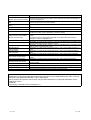
Abbreviations and Terms in This Manual
Unless otherwise started, this manual uses the following abbreviations and terms for
the explanation of MX Component.
Generic Term/Abbreviation
MX Component
IBM-PC/AT compatible
PC CPU module
GX Developer
GX Simulator
MELSECNET/10 board
MELSECNET/H board
CC-Link board
CPU board
AnNCPU
AnACPU
AnUCPU
QnACPU
ACPU
QCPU (A mode)
QCPU (Q mode)
FXCPU
Motion controller CPU
PLC CPU
C24
UC24
QC24
QC24N
QC24(N)
Q series-compatible C24
A - 17
Description
Generic product name for product types SWnD5C-ATC-E and SWnD5C-ACT-EA.
(n denotes version 0 or 2)
-EA denotes a multiple license product.
Abbreviation of the IBM PC/AT or its compatible personal computer
Abbreviation of the MELSEC-Q series compatible PC CPU module
(CONTEC CO., LTD. make).
Abbreviation of Type SW D5C-GPPW-E/SW D5F-GPPW-E GPP function software
package
Abbreviation of Type SW D5C-LLT-E/SW D5F-LLT-E Ladder Logic Test tool
function software package
Abbreviation of Type A70BDE-J71QLP23/A70BDE-J71QLP23GE/A70BDEJ71QBR13/A70BDE-J71QLR23 MELSECNET/10 interface board
Abbreviation of Type Q80BD-J71LP21-25/Q80BD-J71LP21G/Q80BD-J71BR11
MELSECNET/H board
Abbreviation of Type A80BDE-J61BT11 CC-Link system master/local interface board
and Type A80BDE-J61BT13 CC-Link interface board
Abbreviation of Type A80BDE-A2USH-S1 PLC CPU board
Generic term of the A0J2HCPU, A1SCPU, A1SCPU-S1, A1SCPUC24-R2,
A1SHCPU, A1SJCPU, A1SJHCPU, A1NCPU, A2CCPU, A2CCPUC24, A2CCPUC24PRF, A2CJCPU, A2NCPU, A2NCPU-S1, A2SCPU, A2SCPU-S1, A2SHCPU,
A2SHCPU-S1, A3NCPU and A1FXCPU
Generic term of the A2ACPU, A2ACPU-S1, A2ACPUP21/R21, A2ACPUP21-S1,
A3ACPU and A3ACPUP21/R21
Generic term of the A2UCPU, A2UCPU-S1, A2USCPU, A2USCPU-S1, A2ASCPU,
A2ASCPU-S1, A2ASCPU-S30, A2USHCPU-S1, A3UCPU and A4UCPU
Generic term of the Q2ACPU, Q2ACPU-S1, Q2ASCPU, Q2ASCPU-S1, Q2ASHCPU,
Q2ASHCPU-S1, Q3ACPU, Q4ACPU and Q4ARCPU
Generic term of the AnNCPU, AnACPU and AnUCPU
Generic term of the Q02CPU-A, Q02HCPU-A and Q06HCPU-A
Generic term of the Q00JCPU, Q00CPU, Q01CPU, Q02CPU, Q02HCPU, Q06HCPU,
Q12HCPU and Q25HCPU
Note that especially when the CPU is indicated as a different model, the Q00JCPU,
Q00CPU and Q01CPU are described as the Q00J/Q00/Q01CPU, and the Q02CPU,
Q02HCPU, Q06HCPU, Q12HCPU and Q25HCPU as the Q02/Q02H/Q06H/Q12H/
Q25HCPU.
Generic term of the FX0, FX0S, FX0N, FX1, FX1N, FX1NC, FX1S, FX2, FX2C, FX2N and
FX2NC series
Generic term of the A171SHCPU, A172SHCPU, A173UHCPU, A173UHCPU-S1,
A273UHCPU and A273UHCPU-S3
Generic term of the QCPU(Q mode), QCPU(A mode), QnACPU, ACPU, FXCPU and
motion controller CPU
Generic term of the A1SCPUC24-R2, A1SJ71C24-PRF, A1SJ71C24-R2,
A1SJ71C24-R4, A2CCPUC24, A2CCPUC24-PRF, AJ71C24-S6 and AJ71C24-S8
Generic term of the AJ71UC24, A1SJ71UC24-R2, A1SJ71UC24-R4 and
A1SJ71UC24-PRF
Generic term of the AJ71QC24, AJ71QC24-R2, AJ71QC24-R4, A1SJ71QC24-R2 and
A1SJ71QC24-R2
Generic term of the AJ71QC24N, AJ71QC24N-R2, AJ71QC24N-R4, A1SJ71QC24N
and A1SJ71QC24N-R2
Generic term of the QC24 and QC24N
Generic term of the QJ71C24 and QJ71C24-R2
A - 17
Generic Term/Abbreviation
Description
Generic term of the C24, UC24, QC24(N) and Q series-compatible C24
Computer link module
Described as the serial communication module especially to indicate the QC24(N) or
(Serial communication module)
Q series-compatible C24.
Generic term of the AJ71E71, AJ71E71-S3, A1SJ71E71-B2, A1SJ71E71-B5,
E71
A1SJ71E71-B2-S3 and A1SJ71E71-B5-S3
Generic term of the AJ71QE71, AJ71QE71-B5, A1SJ71QE71-B2 and A1SJ71QE71QE71
B5
Generic term of the QJ71E71 and QJ71E71-B2
Q series-compatible E71
Generic term of the E71, QE71 and Q series-compatible E71
Ethernet module
Generic term of the AJ65BT-G4 GPP function peripheral connection module and the
CC-Link G4 module
AJ65BT-G4-S3 GPP function peripheral connection module
Abbreviation of communication made with the PLC CPU using the computer link
Computer link communication
module
(Serial communication)
Described as serial communication especially in communication that uses the
QC24(N) or Q series-compatible C24.
Abbreviation of communication made with the PLC CPU using the Ethernet module
Ethernet communication
Abbreviation of communication made by connecting the IBM-PC/AT compatible to the
CPU COM communication
RS-232C or RS-422 connector of the PLC CPU
Abbreviation of communication made by connecting the IBM-PC/AT compatible to the
CPU USB communication
USB connector of the QCPU (Q mode)
MELSECNET/10
Abbreviation of communication made with the PLC CPU using the MELSECNET/10
communication
board
MELSECNET/H
Abbreviation of communication made with the PLC CPU using the MELSECNET/H
communication
board
Abbreviation of communication made with the PLC CPU using the CC-Link board
CC-Link communication
Abbreviation of communication made with the PLC CPU using the CC-Link G4
CC-Link G4 communication
module
Abbreviation of communication made with the PLC CPU using the CPU board
CPU board communication
Abbreviation of communication made with the PLC CPU on the same base using the
Q series bus communication
PC CPU module
Abbreviation of communication made with the GX Simulator
GX Simulator communication
Abbreviation of user program creation using the communication settings utility
Utility setting type
Abbreviation of user program creation without using the communication settings utility
Program setting type
Generic term of the ActiveX controls offered by MX Component
ACT controls
Microsoft Windows, Microsoft Windows NT, Microsoft Visual Basic and Microsoft Visual C++ are either
trademarks or registered trademarks of Microsoft Corporation in the United States and/or other countries.
Ethernet is the registered trademark of Xerox Corporation.
Other company and product names herein may be either trademarks or registered trademarks of their
respective owners.
SPREAD
Copyright(C) 1999 Far Point Technologies, Inc.
A - 18
A - 18
1 OVERVIEW
MELSOFT
1 OVERVIEW
1
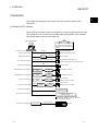
This chapter provides the function outline of the ACT controls offered by MX
Component.
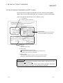
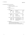
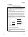
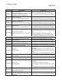
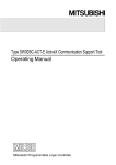
1.1 Outline of ACT controls
These controls are used to create user programs for communication with a PLC CPU.
This enables the user to make communication without being aware of the hardware
and communication protocol on the other end.
IBM-PC/AT compatible
You can make communication with
the specified PLC easily without
being aware of the communication
protocol.
MX Component
RS-232C
Computer link communication
(Serial communication)
Ethernet
Ethernet
board
Ethernet communication
CPU COM communication
Computer link module
(Serial communication module)
RS-232C/RS-422 conversion, RS-232C
USB
CPU USB communication
Ethernet module
ACPU, QnACPU, QCPU(Q mode),
QCPU(A mode), FXCPU, motion controller CPU
QCPU (Q mode)
MELSECNET/10 communication
MELSECNET/10
board
MELSECNET/10
MELSECNET/10 module
MELSECNET/H communication
MELSECNET/H
board
MELSECNET/H
MELSECNET/H module
CC-Link
board
CC-Link
CC-Link communication
CC-Link G4 communication
CC-Link module
RS-232C/RS-422
conversion CC-Link G4
module
(Software version "N" or later)
CC-Link module
CC-Link
(Software version "N" or later)
(Software version "D" or later)
CPU board equivalent
to A2USHCPU-S1
CPU board communication
GX Developer + GX Simulator
(offline debugging)
GX Simulator communication
GX Developer: SW5D5C-GPPW-E or later
GX Simulator : SW5D5C-LLT-E (Ver. B) or later
Must be purchased separately.
Q series bus communication
1-1
PC CPU module
On the same base
(Q mode)
1-1
1 OVERVIEW
MELSOFT
1.2 ACT control and Function Lists
1
The following sections give the lists of ACT controls and functions.
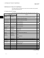
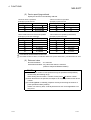
1.2.1 ACT control list
The following table lists the ACT controls included in each DLL offered by MX
Component.
DLL Name
ActMulti.DLL
Included Control Name
For VB, VC++, VBA
ActEasyIF
ActMLEasyIF
ActQCPUQ
ActMLQCPUQ
ActQCPUA
ActPcCom.DLL ActQnACPU
ActComLk.DLL
ActEther.DLL
ActPcUsb.DLL
ActCcG4.DLL
ActBoard.DLL
ActMLQCPUA
ActMLQnACPU
Used to make communication settings easily on the
communication settings utility to make communication.
Used to make communication via the serial port of the
corresponding PLC CPU.
ActACPU
ActMLACPU
ActFXCPU
ActMLFXCPU
ActQJ71C24
ActMLQJ71C24
ActAJ71QC24
ActMLAJ71QC24
Used to make communication via the computer link
module (serial communication module).
ActAJ71UC24
ActMLAJ71UC24
ActAJ71C24
ActMLAJ71C24
ActQJ71E71TCP
ActMLQJ71E71TCP
ActQJ71E71UDP
ActMLQJ71E71UDP
ActAJ71QE71TCP
ActMLAJ71QE71TCP
ActAJ71QE71UDP
ActMLAJ71QE71UDP
Used to make communication via the Ethernet module.
ActAJ71E71TCP
ActMLAJ71E71TCP
ActAJ71E71UDP
ActMLAJ71E71UDP
ActQCPUQUSB
ActMLQCPUQUSB
ActCCG4QnA
ActMLCCG4QnA
Used to make communication via the CC-Link G4
ActCCG4A
ActMLCCG4A
module.
ActMnet10BD
ActMLMnet10BD
ActMnetHBD
ActMLMnetHBD
Used to make communication with or via the network
ActCCBD
ActMLCCBD
board.
ActAnUBD
ActMLAnUBD
ActLLT.DLL
ActLLT
ActMLLLT
ActPcQbf.DLL
ActQCPUQBus
ActMLQCPUQBus
1-2
Application
For VBScript
Used to make communication via the USB port of the
PLC CPU.
Used to make communication with the GX Simulator.
Used to make Q series bus communication with the PC
CPU module.
1-2
1 OVERVIEW
MELSOFT
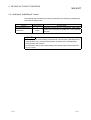
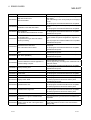
1.2.2 Function list
The following table lists the features of the functions and the functions available for the
ACT controls.
(1) Function list
Refer to "CHAPTER 4 FUNCTIONS" for full information on the functions.
Function Name
Feature
Open
Opens a communication line.
Close
Closes a communication line.
ReadDeviceBlock
Batch-reads data from devices.
WriteDeviceBlock
Batch-writes data to devices.
ReadDeviceRandom
Randomly reads data from devices.
WriteDeviceRandom
Randomly writes data to devices.
SetDevice
Sets one device.
GetDevice
Acquires the data of one device.
ReadBuffer
Reads data from buffer memory.
WriteBuffer
Writes data to buffer memory.
GetClockData
Reads clock data from PLC CPU.
SetClockData
Writes clock data to PLC CPU.
GetCpuType
Reads PLC CPU type.
SetCpuStatus
Remote run/stop/pause of PLC CPU.
EntryDeviceStatus
Registers device status monitor.
FreeDeviceStatus
Deregisters device status monitor.
OnDeviceStatus
Announces event.
(2) Functions available for the ACT controls
Refer to "CHAPTER 4 FUNCTIONS" for full information on the functions
available for the ACT controls.
1-3
1-3
2 ABOUT THE ACT CONTROLS
MELSOFT
2 ABOUT THE ACT CONTROLS
This chapter explains the settings made for use of the ACT controls, the programming
procedures, the device types and the accessible ranges.
2.1 Settings Made for Use of the ACT controls
2
This section describes the setting operation performed for use of the ACT controls.
2.1.1 When using Microsoft Visual Basic 6.0
R
R
Perform the following setting operation when using Visual Basic .
R
(1) Setting the include file
1) Start Visual Basic
menu.
R
and choose the [Project]-[Add Module]
2) Choose the <<Existing>> tab and select "ActDefine.bas".
"ActDefine.bas" is stored in <User specified folder>-<Act><Include> at the time of installation.
3) Registering "ActDefine.bas" adds it to Modules.
2-1
2-1
2 ABOUT THE ACT CONTROLS
MELSOFT
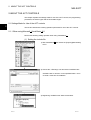
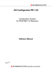
(2) Registering the ACT controls
1) Choose the [Project]-[Components] menu.
2
2) Select the <<Controls>> tab and choose the DLL which
includes the ACT controls you want to use.
3) The ACT controls included in the selected DLL are added
to the toolbox.
2-2
2-2
2 ABOUT THE ACT CONTROLS
MELSOFT
2.1.2 When using Microsoft Visual C++ 6.0
R
R
Perform the following setting operation when using Visual C++ .
R
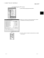
(1) Setting the include file
1) Start Visual C++
R
and choose the [Tools]-[Options] menu.
2) Choose the <<Directories>> tab and set "Include files" in
"Show directories for:".
3) Double-click the item to be set, and browse the include file.
"ActDefine.H" is stored in <User specified folder>-<Act><Include> at the time of installation.
2-3
2-3
2 ABOUT THE ACT CONTROLS
MELSOFT
(2) Registering the ACT control
1) Right-click the form to choose "Insert ActiveX Control".
2) Select the ACT control you want to use.
3) The selected ACT control is pasted to the form.
2-4
2-4
2 ABOUT THE ACT CONTROLS
MELSOFT
(3) Adding the member variable
1) Click the form to choose "Class Wizard".
2) When the left dialog box appears, choose the <<Member
Variables>> tab.
Choose the member variable adding control ID and click
the Add Variable button.
3) When the left screen appears, read the information and
click the OK button.
4) Check the class checkbox and click the OK button.
(To the next page.)
2-5
2-5
2 ABOUT THE ACT CONTROLS
MELSOFT
(From the previous page)
5) Enter the member variable name and click the OK button.
6) Make sure that the member variable has been registered.
2-6
2-6
2 ABOUT THE ACT CONTROLS
MELSOFT
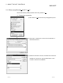
2.1.3 When using VBA
Perform the following setting operation when using VBA.
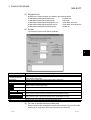
(1) When using Microsoft Excel 2000
R
1) Boot Excel 2000 and choose the [View]-[Toolbars]-[Control
Toolbox] menu.
2) Click the
button of the displayed Control Toolbox. As
this displays a menu, choose the ACT control you want to
use.
3) Paste the selected ACT control to a sheet.
4) Choose the [Tools]-[Macro]-[Visual Basic Editor] menu to
start Visual Basic Editor.
5) Perform programming on Visual Basic Editor.
2-7
2-7
2 ABOUT THE ACT CONTROLS
MELSOFT
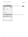
(2) When using Microsoft Access 2000
R
1) Boot Access 2000 and make the database form active.
2) Click the
button of the toolbox. As this displays a
menu, choose the ACT control you want to use.
3) Paste the selected ACT control to a sheet.
4) Choose the [Tools]-[Macro]-[Visual Basic Editor] menu to
start Visual Basic Editor.
5) Perform programming on Visual Basic Editor.
2-8
2-8
2 ABOUT THE ACT CONTROLS
MELSOFT
2.1.4 When using VBScript
Create HTML or ASP using the notepad, commercially available text editor, HTML
creation tool or like.
Refer to the commercially available references and so on for the grammars of HTML
and ASP.
Also refer to the HTML and ASP sample programs installed in MX Component.
2-9
2-9
2 ABOUT THE ACT CONTROLS
MELSOFT
2.2 Programming Procedures
This section gives the procedures of creating a user application.
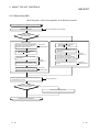
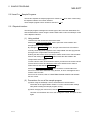
2.2.1 When using Visual Basic
R
When using Visual Basic , create a user application in the following procedure.
R
Power on the IBM-PC/AT compatible and start Windows .
Install MX Component.
Make settings using the
utility setting type?
Refer to the operating manual (startup).
No
Yes
<Program setting type>
<Utility setting type>
Start the communication settings utility
and make communication settings in
accordance with the wizard.
Start Visual Basic .
Refer to the
operating manual.
Add the ACT controls to
Visual Basic .
Refer to
Section 2.1.1.
Start Visual Basic .
Register the ACT control to
Visual Basic .
Refer to
Section 2.1.1.
Create a form and paste the ACT controls
for corresponding communication.
Set the properties of the pasted
ACT controls.
Create a form and paste the ACT
control to the form. (ActEasyIF control)
Set the property of the pasted control.
(Set only the logical station number)
Refer to the
operating manual.
Perform programming using the functions offered by the
corresponding ACT control.
Perform debugging using
the PLC monitor utility?
No
Refer to the
operating manual.
Refer to Chapters 3, 4.
Yes
Refer to the operating manual.
Completion of user application
2 - 10
2 - 10
2 ABOUT THE ACT CONTROLS
2.2.2 When using Visual C++
MELSOFT
R
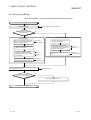
When using Visual C++ , create a user application in the following procedure.
R
Power on the IBM-PC/AT compatible and start Windows .
Refer to the operating manual (startup).
Install MX Component.
Make settings using the
utility setting type?
No
Yes
<Program setting type>
<Utility setting type>
Start the communication settings utility
and make communication settings in
accordance with the wizard.
Start Visual C++ .
Refer to the
operating manual.
Add the ACT control to
Visual C++ .
Start Visual C++ .
Create a form and paste the ACT control
for corresponding communication.
Register the ACT control to
Visual C++ .
Create a form and paste the ACT
control to the form. (ActEasyIF control)
Refer to
Section 2.1.2.
Set the property of the pasted control.
(Set only the logical station number)
No
Refer to the
operating manual.
Refer to the
operating manual.
Perform programming using the functions offered by the
corresponding ACT control.
Perform debugging using
the PLC monitor utility?
Using Class Wizard, define the pasted
ACT control as a dialog member.
Set the properties of the pasted ACT
control.
Using Class Wizard, define the pasted
ACT control as a dialog member.
Refer to
Section 2.1.2.
Refer to Chapters 3, 4.
Yes
Refer to the operating manual.
Completion of user application
2 - 11
2 - 11
2 ABOUT THE ACT CONTROLS
MELSOFT
2.2.3 When using VBA
When using VBA, create a user application in the following procedure.
Power on the IBM-PC/AT compatible and start Windows .
Refer to the operating manual (startup).
Install MX Component.
Make settings using the
utility setting type?
No
Yes
<Program setting type>
<Utility setting type>
Start the communication settings utility
and make communication settings in
accordance with the wizard.
Start Visual Basic Editor and create
applications.
Start Microsoft Excel 2000 or
Microsoft Access 2000.
Generate the corresponding
communication control so that MX
Component may be utilized on VBA.
Start Visual Basic Editor and create
applications.
Refer to
Section 2.1.3.
Generate the ActEasyIF control so that
MX Component may be utilized on VBA.
Set the property of the pasted control.
(Set only the logical station number)
No
Set the properties of the pasted ACT
control.
Refer to
Section 2.1.3.
Refer to the
operating manual.
Refer to the
operating manual.
Perform programming using the functions offered by the
corresponding ACT control.
Perform debugging using
the PLC monitor utility?
Start Microsoft Excel 2000 or
Microsoft Access 2000.
Refer to the
operating manual.
Refer to Chapters 3, 4.
Yes
Refer to the operating manual.
Completion of user application
2 - 12
2 - 12
2 ABOUT THE ACT CONTROLS
MELSOFT
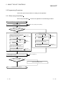
2.2.4 When using VBScript
When using VBScript, create a user application in the following procedure.
Power on the IBM-PC/AT compatible and start Windows .
Refer to the operating manual (startup).
Install MX Component.
Make settings using the
utility setting type?
No
Yes
<Program setting type>
<Utility setting type>
Start the communication settings utility
and make communication settings in
accordance with the wizard.
Refer to the
operating manual.
Create a home page using the text
editor and HTML editor.
On the home page, generate the
ActMLEasyIF control so that MX
Component controls may be utilized
using VBScript.
Set the property of the pasted control.
(Set only the logical station number)
Refer to
Section 2.1.4.
No
On the home page, generate the
corresponding communication control
so that MX Component controls may
be utilized using VBScript.
Refer to
Section 2.1.4.
Set the properties of the pasted ACT
control.
Refer to the
operating manual.
Refer to the
operating manual.
Perform programming using the functions offered by the
corresponding ACT control.
Perform debugging using
the PLC monitor utility?
Create a home page using the text
editor and HTML editor.
Refer to Chapters 3, 4.
Yes
Refer to the operating manual.
Completion of user application
2 - 13
2 - 13
2 ABOUT THE ACT CONTROLS
MELSOFT
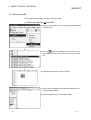
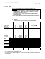
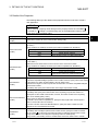
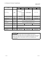
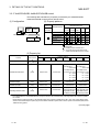
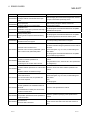
2.3 Device Types
This section explains the devices that may be specified for the functions.
POINT
(1) For the functions (ReadDeviceBlock, WriteDeviceBlock, ReadDeviceRandom,
WriteDeviceRandom, SetDevice and GetDevice), specify the devices in the
form of "device name + device number".
For the device numbers, note the differences between octal, decimal and
hexadecimal numbers.
(2) When specifying bit devices for ReadDeviceBlock or WriteDeviceBlock, specify
the device number as a multiple of 16.
(3) Only the devices indicated in this section are supported.
Do not use unsupported devices.
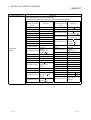
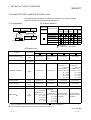
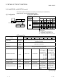
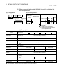
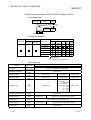
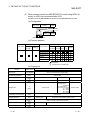
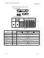
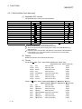
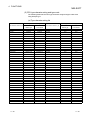
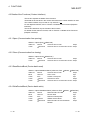
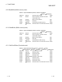
(1) Common
The following device types are common to all communication paths.
Device
Device Name Device No. Type Representation
Remarks
Function input
FX
Decimal
Bit
—
Function output
FY
Decimal
Bit
—
Function register
FD
Decimal
Word
Special relay
SM
Decimal
Bit
—
Special register
SD
Decimal
Word
—
X
Hexadecimal
Bit
Octal for FXCPU
Output relay
Y
Hexadecimal
Bit
Octal for FXCPU
Internal relay
M
Decimal
Bit
2
Latch relay
L
Decimal
Bit
2
Annunciator
F
Decimal
Bit
—
Edge relay
V
Decimal
Bit
—
Link relay
B
Decimal
Bit
—
Input relay
4 words/1 point
Data register
D
Decimal
Word
—
Link register
W
Hexadecimal
Word
—
Contact
TS
Decimal
Bit
—
Coil
TC
Decimal
Bit
—
Present value
TN
Decimal
Word
—
Contact
CS
Decimal
Bit
—
Timer
Counter
Coil
CC
Decimal
Bit
Present value
CN
Decimal
Word
Contact
SS
Decimal
Bit
For ACPU, use timer to specify.
SC
Decimal
Bit
For ACPU, use timer to specify.
For ACPU, use timer to specify.
Retentive timer Coil
Present value
—
For FXCPU, 200 or more is 32-bit data.
SN
Decimal
Word
Link special relay
SB
Hexadecimal
Bit
—
Link special register
SW
Hexadecimal
Word
—
S
Decimal
Bit
Step relay
1
2
Bit: Bit device
Word: Word device
1: For batch operation, operation is performed continuously in units of one word.
For random operation, only the first one word is read.
2: For the QCPU (A mode) and ACPU, the M, L and S devices have the same regions independently of the device setting
in the parameters.
2 - 14
2 - 14
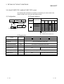
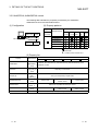
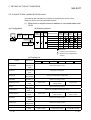
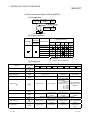
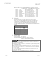
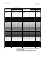
2 ABOUT THE ACT CONTROLS
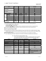
Device
MELSOFT
Device Name Device No. Type Representation
Accumulator
Index register
Remarks
A
Decimal
Word
5
Z
Decimal
Word
5
V
Decimal
Word
5
R
Decimal
Word
3
ZR
Decimal
Word
—
ER \R
Decimal
Word
4
Link input
J \X
Hexadecimal
Bit
4
Link output
J \Y
Hexadecimal
Bit
4
J \B
Hexadecimal
Bit
4
File register
Extended file register
Direct Link relay
link 6 Link special relay
J \SB
Hexadecimal
Bit
4
Link register
J \W
Hexadecimal
Bit
4
Link special register
Special direct buffer
memory 7 9
J \SW
Hexadecimal
Hexadecimal
/decimal
Word
4
U \G
Word
4,
8
Bit: Bit device Word: Word device
3: To specify the extended file register, describe "\" between the block number part and file register part.
Specifying R
specifies R of block No. 0.
Specifying ER0\R
returns an error.
Specifying ER
does not enable extension representation (indirect specification, digit specification).
\R
4: For direct specification, describe "\" between the direct specification part and device specification part.
5: Cannot be used when E71 is relayed.
6: For J , specify the network number.
7: Specify the special module I/O number (hexadecimal) for U , and the buffer memory address (decimal) for G
.
(Example: Specify "U20\G100" when the special module I/O number is 200H and the buffer memory address is 100.)
8: FXCPU cannot be used.
9: In a multi-QCPU configuration, an error will occur if the shared memory of the host QCPU is specified.
Also, independently of the host or other CPU, an error will occur if write to the shared memory is performed.
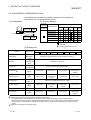
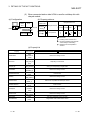
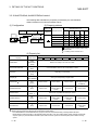
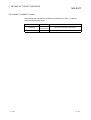
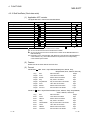
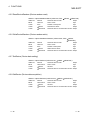
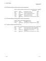
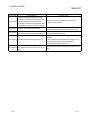
(2) For CC-Link communication only
For CC-Link communication only, the devices in the following table can be used when
own board access is made. They cannot be used for other communication paths.
Device
Device Name Device No. Type Representation
Special relay
SM
Bit
Decimal
Special register
SD
Word
Decimal
Link special register (for CC-Link)
SB
Bit
Hexadecimal
Link special register (for CC-Link)
SW
Word
Hexadecimal
Remote input
X
Bit
Hexadecimal
Remote output
Y
Bit
Hexadecimal
Link register
W
Word
Hexadecimal
Remote register
WW
Word
Hexadecimal
(write area for CC-Link)
Remote register
WR
Word
Hexadecimal
(read area for CC-Link)
Buffer memory
ML
Word
Random access buffer
MC
Word
Automatic refresh buffer
MF
Bit
2 - 15
Remarks
Special relay of own board
Special register of own board
Link special relay of own board
Link special register of own board
RX
RY
—
RWw
RWr
Buffer memory of own station CC-Link
module
Random access buffer in buffer memory
Hexadecimal
of own station CC-Link module
Automatic refresh buffer of own station
Hexadecimal
CC-Link module
Hexadecimal
2 - 15
2 ABOUT THE ACT CONTROLS
MELSOFT
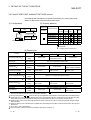
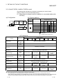
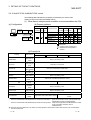
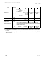
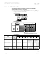
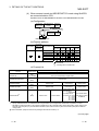
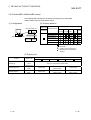
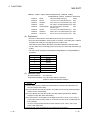
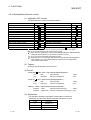
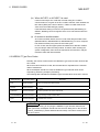
(3) About device extension representation
The following table indicates whether the device extension representations are
usable or not for the available CPUs.
They cannot be used with ReadDeviceBlock and WriteDeviceBlock.
When the ActAJ71E71TCP, ActMLAJ71E71TCP, ActAJ71QE71TCP or
ActMLAJ71QE71TCP control is used, device expansion representation is
unusable.
Target CPU
Device Extension
Representation
QCPU
QCPU
(Q mode)
(A mode)
QnACPU
ACPU
FXCPU
Motion
controller CPU
Digit specification
2
(example: K4M0)
Bit specification
(example: D0.1)
3
Index qualification
(example: M100Z0)
1
4
: Usable
: Unusable
1: Unusable when QE71 is relayed.
2: FX/FX, DX/DY and T/C/ST (contact, coil) cannot be specified.
3: Z, V, T/C/ST (present value) cannot be specified.
4: FX/FX, DX/DY, T/C/ST (contact, coil), Z and S cannot be specified.
2.4 Accessible Devices and Ranges
Refer to the MX Component operating manual for the accessible devices and ranges
for corresponding communication.
2 - 16
2 - 16
3 DETAILS OF THE ACT CONTROLS
MELSOFT
3 DETAILS OF THE ACT CONTROLS
This chapter describes the details of the ACT controls, the details of the properties,
and the possessed property list.
3.1 Details of the ACT Controls
The following table lists the definitions and usable setting types of the ACT controls.
Control Name
Definition
For VB, VC++, VBA
3
For VBScript
ActEasyIF
ActMLEasyIF
ActQJ71E71TCP
ActMLQJ71E71TCP
ActQJ71E71UDP
ActMLQJ71E71UDP
ActAJ71QE71TCP
ActMLAJ71QE71TCP
ActAJ71QE71UDP
ActMLAJ71QE71UDP
ActAJ71E71TCP
ActMLAJ71E71TCP
ActAJ71E71UDP
ActMLAJ71E71UDP
ActQCPUQ
ActMLQCPUQ
ActQCPUA
ActMLQCPUA
ActQnACPU
ActMLQnACPU
ActACPU
ActMLACPU
ActFXCPU
ActMLFXCPU
ActQJ71C24
ActMLQJ71C24
ActAJ71QC24
ActMLAJ71QC24
ActAJ71UC24
ActAJ71C24
ActMLAJ71UC24
ActMLAJ71C24
ActQCPUQUSB
ActMLQCPUQUSB
ActCCG4QnA
ActMLCCG4QnA
ActCCG4A
ActMLCCG4A
ActMnet10BD
ActMnetHBD
ActCCBD
ActAnUBD
ActLLt
ActQCPUQBus
ActMLMnet10BD
ActMLMnetHBD
ActMLCCBD
ActMLAnUBD
ActMLLLt
ActMLQCPUQBus
3-1
Usable
Setting
Type
Can communicate with any communication path.
U
Use the communication settings utility to set the information for communication.
Used for Ethernet communication where the connected module is the Q seriesP
compatible E71 (TCP/IP communication).
Used for Ethernet communication where the connected module is the Q seriesP
compatible E71 (UDP/IP communication).
Used for Ethernet communication where the connected module is the QE71
P
(TCP/IP communication).
Used for Ethernet communication where the connected module is the QE71
P
(UDP/IP communication).
Used for Ethernet communication where the connected module is the E71
P
(TCP/IP communication).
Used for Ethernet communication where the connected module is the E71
P
(UDP/IP communication).
Used for CPU COM communication where the connected PLC CPU is the
P
QCPU (Q mode).
Used for CPU COM communication where the connected PLC CPU is the
P
QCPU (A mode).
Used for CPU COM communication where the connected PLC CPU is the
P
QnACPU.
Used for CPU COM communication where the connected PLC CPU is the
P
ACPU (including motion controller CPU).
Used for CPU COM communication where the connected PLC CPU is the
P
FXCPU.
Used for computer link communication where the connected module is the Q
P
series-compatible C24.
Used for computer link communication where the connected module is the
P
QC24(N).
Used for computer link communication where the connected module is the UC24.
P
Used for computer link communication where the connected module is the C24.
P
Used for USB communication where the connected PLC CPU is the QCPU (Q
P
mode).
Used for CC-Link G4 communication where the connected module is the
P
AJ65BT-G4 (QnA mode).
Used for CC-Link G4 communication where the connected module is the
P
AJ65BT-G4 (A mode).
Used for MELSECNET/10 communication.
P
Used for MELSECNET/H communication.
P
Used for CC-Link communication.
P
Used for CPU board communication.
P
Used for GX Simulator communication.
P
Used for Q series bus communication.
U : Utility setting type
P : Program setting type
3-1
3 DETAILS OF THE ACT CONTROLS
MELSOFT
3.2 Details of the Properties
The following tables give the details of the properties which must be set to create a
user application.
POINT
When entering a property value directly into the property window of Visual Basic
or Visual C++ , change a character string such as a hexadecimal number or CPU
type into a decimal property value.
R
R
Property Name (Type)
ActLogicalCtationNumber
(LONG)
Description
3
Logical station number set on the communication settings utility.
Specify the network number on the MELSECNET/10(H). (Specify "0x00" when specifying the
own station.)
Specify as follows for multidrop connection (via Q series-compatible C24, QJ61BT11).
ActNetworkNumber
ActIntelligentPreferenceBit value
(LONG)
Description
0x00
Specify the own network.
0x01
Specify another network of multidrop destination.
Specify the station number for MELSECNET/10(H) or CC-Link. (Specify "0x00" when specifying
the own station.)
Handled as the own station when access to the CPU of the CPU board is made.
ActStationNumber
(LONG)
ActUnitNumber
(LONG)
Specify as follows for multidrop connection (via Q series-compatible C24, QJ61BT11).
ActIntelligentPreferenceBit value
Description
0x00
Specify the own network.
0x01
Specify another network of multidrop destination.
Specify the module number of the computer link module or the station number when the target is
the Q series-compatible intelligent special function module. However, specify "00x0" when setting
the QnA series own station (module loaded to the own station CPU).
Invalid when the target is not the computer link communication or Q series-compatible intelligent
special function module.
For multidrop link, specify the module number of the target computer link module.
Specify the module number of the computer link module, QE71 or Q series-compatible E71.
For multidrop link, specify the module number of the requesting computer link module. For
multidrop link via CPU COM communication, however, the module number of the requesting
station is not needed (specify "00x0").
ActConnectUnitNumber
Specify "0x00" for other than multidrop link.
(LONG)
For the QE71 and Q series-compatible E71, specify the relay target station number (fixed to
"0x00" for access within the own network).
For access to another network via MELSECNET/10, specify the station number set in the
parameter of the connected Ethernet module.
ActIONumber
(LONG)
3-2
Specify the module I/O number.
For multidrop link or intelligent special function module access, specify the actual I/O number
(first I/O number 16) of the target computer link module or intelligent special function module
(specify the I/O number of the relayed or requesting station for multidrop link).
Specify "0x3FF" when making access to another station via the own station CPU or network.
3-2
3 DETAILS OF THE ACT CONTROLS
MELSOFT
Property Name(Type)
Description
Specify the target CPU to communicate with.
In the parameter, specify any of the CPU types in the following table.
Property value
(Property window input
Property value
Target CPU
(Property window input
value)
CPU_Q00JCPU (0x30)
Q00JCPU
CPU_A2SHCPU(0x109) A2SHCPU ( S1)
CPU_Q00CPU (0x31)
Q00CPU
CPU_A3NCPU (0x10A) A3NCPU
CPU_Q01CPU (0x32)
Q01CPU
CPU_Q02CPU (0x22)
Q02(H)CPU
CPU_Q06CPU (0x23)
Q06HCPU
CPU_Q12CPU (0x24)
Q12HCPU
CPU_Q25CPU (0x25)
Q25HCPU
CPU_Q02CPU_A (0x141) Q02(H)CPU-A
CPU_A2ACPU (0x10C)
CPU_A3ACPU (0x10D)
CPU_Q2ACPU (0x11)
ActCpuType
A2ACPU ( S1),
A2ACPUP21/R21( S1)
A3ACPU,
A3ACPUP21/R21
A2UCPU ( S1),
CPU_A2UCPU (0x10E) A2USCPU ( S1),
A2ASCPU ( S1)
CPU_Q06CPU_A (0x142) Q06HCPU-A
(LONG)
Target CPU
value)
Q2ACPU, Q2ASCPU,
CPU_A2USHS1CPU
A2USHCPU-S1CPU,
Q2ASHCPU
(0x10F)
CPU board
Q2ACPU-S1,
CPU_Q2AS1CPU (0x12) Q2ASCPU( S1),
CPU_A3UCPU (0x110)
A3UCPU,
A2ASCPU-S30
Q2ASHCPU( S1)
CPU_A4UCPU (0x111)
A4UCPU
CPU_Q3ACPU (0x13)
Q3ACPU
CPU_FX0CPU (0x201)
FX0, FX0S
CPU_Q4ACPU (0x14)
Q4ACPU, Q4ARCPU
CPU_A0J2HCPU (0x102) A0J2HCPU
CPU_A1FXCPU (0x103) A1FXCPU
A1SCPU( S1),
CPU_A1SCPU (0x104)
CPU_FX0NCPU (0x202) FX0N
CPU_FX1CPU (0x203)
FX1
CPU_FX2CPU (0x204)
FX2, FX2C
CPU_FX2NCPU (0x205) FX2N, FX2NC
A1SCPUC24-R2,
CPU_FX1SCPU (0x206) FX1S
A1SJCPU
CPU_FX1NCPU (0x207) FX1N, FX1NC
CPU_A1SHCPU (0x105) A1SHCPU, A1SJHCPU
CPU_A171SHCPU (0x601)
A171SHCPU
CPU_A1NCPU (0x106)
A1NCPU
CPU_A172SHCPU (0x602)
A172SHCPU
A2CCPU,
CPU_A273UHCPU (0x603) A273UHCPU (
S3)
A2CCPUC24 ( PRF),
CPU_A173UHCPU (0x604) A173UHCPU (
S1)
CPU_A2CCPU (0x107)
A2CJCPU
CPU_A2NCPU (0x108)
A2NCPU ( S1),
CPU_BOARD (0x401)
For own board
access 1
A2SCPU ( S1)
*1: Except CPU board
3-3
3-3
3 DETAILS OF THE ACT CONTROLS
MELSOFT
Property Name(Type)
Description
Specify the connection port number of the IBM-PC/AT compatible.
When the Ethernet module is connected, set any value as the port number of the requesting
source (IBM-PC/AT compatible).
When "=0" was specified as the port number, the MELSECNET/10 routing system should be
the automatic response system. (When the system selected is other than the automatic
response system via QE71, you should set the fixed value "5001".)
Also, when the control for network board is used, specify the first board as PORT_1, and the
second and subsequent boards as PORT_2, PORT_3 ...
Property value
(Property window input value)
Description
ActPortNumber
PORT_1
(0x01)
Communication port 1
(LONG)
PORT_2
(0x02)
Communication port 2
PORT_3
(0x03)
Communication port 3
PORT_4
(0x04)
Communication port 4
PORT_5
(0x05)
Communication port 5
PORT_6
(0x06)
Communication port 6
PORT_7
(0x07)
Communication port 7
PORT_8
(0x08)
Communication port 8
PORT_9
(0x09)
Communication port 9
PORT_10 (0x0A)
Communication port 10
Specify the baudrate for computer link communication.
ActBaudRate
(LONG)
ActDataBit(LONG)
Property value
(Property window input
value)
Description
Property value
(Property window input
value)
Description
BAUDRATE_300
(300)
300bps
BAUDRATE_9600
(9600)
9600bps
BAUDRATE_600
(600)
600bps
BAUDRATE_19200
(19200)
19200bps
BAUDRATE_1200
(1200)
1200bps
BAUDRATE_38400
(38400)
38400bps
BAUDRATE_2400
(2400)
2400bps
BAUDRATE_57600
(57600)
57600bps
BAUDRATE_4800
(4800)
4800bps
BAUDRATE_115200
(115200)
115200bps
Specify the number of bits (7 or 8) of the byte data sent and received for computer link
communication.
Specify the parity system used for computer link communication.
ActParity
(LONG)
3-4
Property value
(Property window input value)
Description
NO_PARITY
(0)
No parity
ODD_PARITY
(1)
Odd
EVEN_PARITY (2)
Even
3-4
3 DETAILS OF THE ACT CONTROLS
MELSOFT
Property Name(Type)
Description
Specify the number of stop bits used for computer link communication
ActStopBit
(LONG)
Property value
(Property window input value)
STOPBIT_ONE
Description
(0)
1 stop bit
STOPBITS_TWO (2)
2 stop bits
Specify the control setting of the signal line.
Property value
(Property window input value)
Description
ActControl
TRC_DTR
(0x01)
DTR control
(LONG)
TRC_RTS
(0x02)
RTS control
TRC_DRT_AND_RTS (0x07)
TRC_DTR_OR_RTS
(0x08)
DTR control and RTS control
DTR control or RTS control
ActHostAddress(BSTR)
Pointer which indicates the connection host name (IP address) for Ethernet communication.
ActCpuTimeOut(LONG)
Specify the CPU watchdog timer for Ethernet communication. (Unit = " 250ms")
ActTimeOut(LONG)
ActSumCheck
(LONG)
Set the time-out value of communication between the IBM-PC/AT compatible and PLC. (Unit = "ms")
For MX Component, depending on the communication path, the internal processing of time-out may
be repeated 3 times. In this case, it may take 3 times the time-out value that has been set.
Specify whether sumcheck is made or not.
Valid only via computer link module.
Property value
(Property window input value)
Description
NO_SUM_CHECK (0)
Without sumcheck
SUM_CHECK
(1)
With sumcheck
Specify the requesting network number when the QE71 or Q series-compatible E71 is
ActSourceNetworkNumber specified.
Specify the same network number as for the connected QE71 or Q series-compatible E71
(LONG)
(network number specified in the network parameter).
Specify the requesting station number (IBM-PC/AT compatible side station number) when the
ActSourceStationNumber QE71 or Q series-compatible E71 is specified.
Make setting to avoid setting the same station number as that of the QE71 set within the same
(LONG)
Ethernet loop.
Specify the port number of the target when Ethernet communication is specified.
For access to another network, specify the relay destination port number.
For other than the automatic response system, make setting as indicated in the following table.
ActDestinationPort
Number
(LONG)
Communication
Setting
QE71(UDP/IP)
Fixed to "5001"
Q series-compatible E71 (TCP/IP)
Fixed to "5002"
Q series-compatible E71 (UDP/IP)
Fixed to "5001"
For multidrop connection (via Q series-compatible C24/CC-Link), specify the actual I/O number
ActDestinationIONumber (first I/O 16) of the last access target station. (When the target is the intelligent special function
module)
(LONG)
When the target is the CPU, specify "0x3FF".
3-5
3-5
3 DETAILS OF THE ACT CONTROLS
Property Name(Type)
ActMultiDropChannel
Number
(LONG)
Description
For multidrop connection (via Q series-compatible C24/CC-Link), specify the multidrop
connection channel number (Ch1/Ch2).
Invalid for other connections.
You can select the MELSECNET/H or MELSECNET/10 mode to make access to the own
station QCPOU (Q mode) or to the QCPU (Q mode) via the MELSECNET/H when using the
ActQJ71C24, ActQJ71E71TCP, ActQJ71E71UDP, ActQCPUQ or ActQCPUQUSB control.
When the control used is other than the above, the mode is fixed to the MELSECNET/10 mode.
ActThroughNetworkType
(LONG)
ActIntelligent
PreferenceBit
(LONG)
ActDidPropertyBit
(LONG)
MELSOFT
Property value
Description
0x00
MELSECNET/H mode
0x01
MELSECNET/10 mode
For multidrop connection (via Q series-compatible C24/CC-Link), specify whether the network
of the multidrop link destination will be relayed or not. (To differentiate the own network
module.)
Property value
Description
0x00
Another network of multidrop link destination is not accessed.
0x01
Another network of multidrop link destination is accessed.
For access to the Q series-compatible own station intelligent special function module (intelligent
special function module load on the own station CPU), making the following setting invalid
makes it unnecessary to specify "ActUnitNumber". (Only "ActIONumber" is used to specify the
module I/O number.)
Property value
Description
0x00
Module number is made valid.
0x01
Module number is made invalid.
For multidrop connection (via Q series-compatible C24/CC-Link), making the following setting
invalid makes it unnecessary to specify "ActDestinationIONumber".
However, when the following setting is made invalid, "ActDidPropertyBit" must be made valid.
(Use "ActUnitNumber" to specify.)
ActDsidPropetyBit
(LONG)
Property value
Description
0x00
I/O number of the last access target station is made valid.
0x01
I/O number of the last access target station is made invalid.
Specify the packet type for communication with the A series or QnA series Ethernet module.
ActPacketType
(LONG)
ActPassword
(BSTR)
3-6
Property value
(Property window input value)
Description
PACKET_ASCII (2)
ASCII packet
PACKET_BINARY (3)
Binary packet
Specify the password set to the Q series-compatible E71 to unlock that password.
It is ignored if the communication target is other than the Q series-compatible E71 when the
ActEasyIF or ActMLEasyIF control is used.
Specifying any characters other than alphanumeric characters will result in a character code
conversion error (0xF1000001) at the Open time.
3-6
3 DETAILS OF THE ACT CONTROLS
MELSOFT
3.3 Lists of Properties Possessed by the ACT Controls
This section lists the properties possessed by the ACT controls and their default
values. How to use the manual in Section 3.3.1 to Section 3.3.25 is provided below.
<How to use the manual in Section 3.3.1 to Section 3.3.25>
Configuration
Sketch of system configuration
Property patterns
Indicates the accessible ranges of the used
control and the patterns of the properties.
Property list
(1) Property
Gives the property name.
(2) Default value
Gives the default value of the property.
The default values used when the properties are changed in the
program are given within the "parentheses".
(3) Property pattern
Gives the property settings necessary to make communication settings.
Refer to the "property pattern table" for the property pattern numbers.
POINT
The default values indicated are the property values shown in the property window
of Visual Basic or Visual C++ .
The default values of the properties, whose values must be changed in other than
decimal when changed in a program, are indicated in parentheses.
R
3-7
R
3-7
3 DETAILS OF THE ACT CONTROLS
MELSOFT
3.3.1 ActEasyIF, ActMLEasyIF control
The following table indicates the property possessed by the ActEasyIF, ActMLEasyIF
control and its default value.
Property
Default Value
ActLogicalStationNumber
ActPassword
0
Empty
Property Pattern
Logical station number set on the communication settings utility
Password set to the Q series-compatible E71 on the connected
station side
POINT
Depending on the communication path (Ethernet communication, MELSECNET/10
communication, etc.), there will be restrictions as placed on the corresponding
communication path controls.
For restrictions, refer to the corresponding communication path controls (Sections
3.3.2 to 3.3.25).
3-8
3-8
3 DETAILS OF THE ACT CONTROLS
MELSOFT
3.3.2 ActQJ71E71TCP, ActMLQJ71E71TCP control
The following table indicates the properties possessed by the ActQJ71E71TCP,
ActMLQJ71E71TCP control and their default values.
(1) Configuration
(2) Property patterns
Connected
Station CPU
Connected Q series
station CPU -compatible E71
Relayed
module
QCPU
(Q mode)
Relayed network
Relayed Station CPU
Relayed Network
QCPU
QCPU
QnA ACPU
FXCPU
(Q mode) (A mode) CPU
1
MELSECNET/H
MELSECNET/10
Relayed Relayed
station CPU module
MELSECNET(II)
Ethernet
IBM-PC/AT compatible
Computer link
CC-Link
: Accessible (Property pattern within circle)
: Inaccessible
1 : Including motion controller CPU
(3) Property list
Property
ActConnectUnitNumber 1
ActCpuType
ActDestinationIONumber
Property Patterns
Default Value
0
(0x00)
Fixed to 0x00
34
(CPU_Q02CPU)
0
(0x00)
Connected station
side module station
number
Fixed to 0x00
Fixed to 0x00
CPU type corresponding to target station
Target station side
Target station side
For single CPU
For single CPU
0x3FF fixed
0x3FF fixed
For multiple CPUs
For multiple CPUs
Fixed to 0x00
Fixed to 0x00
Connected CPU: 0x3FF Connected CPU: 0x3FF
No. 1: 0x3E0
No. 1: 0x3E0
No. 2: 0x3E1
No. 2: 0x3E1
No. 3: 0x3E2
No. 3: 0x3E2
No. 4: 0x3E3
No. 4: 0x3E3
ActDidPropertyBit
1
(0x01)
Fixed to 0x01
Fixed to 0x01
Fixed to 0x00
Fixed to 0x00
ActDsidPropertyBit
1
(0x01)
Fixed to 0x01
Fixed to 0x01
Fixed to 0x00
Fixed to 0x00
ActHostAddress
1.1.1.1
ActIONumber 6
1023
(0x3FF)
Host name or IP address of connected station side module
Target station side
For single CPU
For single CPU
0x3FF fixed
0x3FF fixed
For multiple CPUs
For multiple CPUs
Connected station
Connected CPU: 0x3FF
Connected CPU: 0x3FF side relayed module
No. 1: 0x3E0
No. 1: 0x3E0 I/O address
No. 2: 0x3E1
No. 3: 0x3E2
No. 4: 0x3E3
Connected station
side relayed module
I/O address
No. 2: 0x3E1
No. 3: 0x3E2
No. 4: 0x3E3
1: For access to another station via MELSECNET/10 (for the property pattern of
), specify the station number of the connected station side Q
series-compatible E71 set in the Ethernet parameter of the connected station side Q series-compatible E71.
6: As the I/O address, specify the value found by dividing the actual first I/O number by 16.
(To next page)
3-9
3-9
3 DETAILS OF THE ACT CONTROLS
Property
Default Value
ActMultiDropChannelNumber
0
(0x00)
ActNetworkNumber
1
(0x01)
2
MELSOFT
Property Patterns
Fixed to 0x00
Network number of
target station side
module
Fixed to 0x00
Network number of
target station side
module
0x00 or 0x02
5
Connected station
side Q seriescompatible E71
network number
Fixed to 0x00
Connected station
side Q seriescompatible E71
network number
ActPassword
Empty
Password set to the Q series-compatible E71 on the connected station side
ActSourceNetworkNumber
1
(0x01)
IBM-PC/AT compatible side network number
ActSourceStationNumber 4
2
(0x02)
IBM-PC/AT compatible side station number
ActStationNumber 2
1
(0x01)
Connected station
side module station
number
ActThroughNetworkType
0
(0x00)
QCPU (Q mode): 0x00 (MELSECNET/H only), other than QCPU (Q mode): 0x01
(including MELSECNET/10). Note that the setting must be the same as set in the network
parameter of the GPP function.
ActTimeOut
10000
Any value specified by user in ms units.
ActUnitNumber
0
(0x00)
3
Fixed to 0x00
Connected station
side module station
number
Fixed to 0x00
Connected station
side Q seriescompatible E71
station number
Target station side
module station
number
Connected station
side Q seriescompatible E71
station number
Target station side
module station
number (valid)
2: For the property pattern of
or , specify the value set in the target station side parameter for ActNetworkNumber and ActStationNumber.
3: Specify the same network number as the MELSECNET/10 network number set to the Q series-compatible E71 in the Ethernet parameter
setting of the target station side Q series-compatible E71.
4: Specify the station number on the IBM-PC/AT compatible side to avoid setting the same station number as set to the Q series-compatible E71
within the same Ethernet loop.
5: If the following conditions are all satisfied, change the ActMultiDropChannelNumber value to 0x00.
• A remote password has been set to the Q series-compatible E71 connected.
• The version of the Q series-compatible E71 connected is J or earlier.
3 - 10
3 - 10
3 DETAILS OF THE ACT CONTROLS
MELSOFT
3.3.3 ActQJ71E71UDP, ActMLQJ71E71UDP control
The following table indicates the properties possessed by the ActQJ71E71UDP,
ActMLQJ71E71UDP control and their default values.
(1) Configuration
(2) Property patterns
Connected Q series
station CPU -compatible E71
Connected
Station CPU
Relayed
module
QCPU
(Q mode)
Relayed network
Relayed Station CPU
Relayed Network
QCPU
QCPU
QnA ACPU
FXCPU
(Q mode) (A mode) CPU
1
MELSECNET/H
MELSECNET/10
Relayed Relayed
station CPU module
MELSECNET(II)
Ethernet
IBM-PC/AT compatible
Computer link
CC-Link
: Accessible (Property pattern within circle)
: Inaccessible
1 : Including motion controller CPU
(3) Property list
Property
ActConnectUnitNumber 1
ActCpuType
ActDestinationIONumber
Property Patterns
Default Value
0
(0x00)
Fixed to 0x00
34
(CPU_Q02CPU)
0
(0x00)
Connected station
side module station
number
Fixed to 0x00
Fixed to 0x00
CPU type corresponding to target station
Target station side
Target station side
For single CPU
For single CPU
0x3FF fixed
0x3FF fixed
For multiple CPUs
For multiple CPUs
Fixed to 0x00
Fixed to 0x00
Connected CPU: 0x3FF Connected CPU: 0x3FF
No. 1: 0x3E0
No. 1: 0x3E0
No. 2: 0x3E1
No. 2: 0x3E1
No. 3: 0x3E2
No. 3: 0x3E2
No. 4: 0x3E3
No. 4: 0x3E3
ActDidPropertyBit
1
(0x01)
Fixed to 0x01
Fixed to 0x01
Fixed to 0x00
Fixed to 0x00
ActDsidPropertyBit
1
(0x01)
Fixed to 0x01
Fixed to 0x01
Fixed to 0x00
Fixed to 0x00
ActHostAddress
1.1.1.1
ActIONumber 7
1023
(0x3FF)
Host name or IP address of connected station side module
Target station side
For single CPU
For single CPU
0x3FF fixed
0x3FF fixed
For multiple CPUs
For multiple CPUs
Connected station
Connected CPU: 0x3FF
Connected CPU: 0x3FF side relayed module
No. 1: 0x3E0
No. 1: 0x3E0 I/O address
No. 2: 0x3E1
No. 3: 0x3E2
No. 4: 0x3E3
Connected station
side relayed module
I/O address
No. 2: 0x3E1
No. 3: 0x3E2
No. 4: 0x3E3
1: For access to another station via MELSECNET/10 (for the property pattern of ), specify the station number of the connected station side Q
series-compatible E71 set in the Ethernet parameter of the connected station side Q series-compatible E71.
7: As the I/O address, specify the value found by dividing the actual first I/O number by 16.
(To next page)
3 - 11
3 - 11
3 DETAILS OF THE ACT CONTROLS
MELSOFT
Property Patterns
Property
Default Value
ActMultiDropChannelNumber
0
(0x00)
ActNetworkNumber
1
(0x01)
2
Fixed to 0x00
Network number of
target station side
module
Fixed to 0x00
Network number of
target station side
module
0x00 or 0x02
6
Connected station
side Q seriescompatible E71
network number
Fixed to 0x00
Connected station
side Q seriescompatible E71
network number
ActPassword
Empty
Password set to the Q series-compatible E71 on the connected station side
ActPortNumber 4
5001
IBM-PC/AT compatible side port number
ActSourceNetworkNumber
1
(0x01)
IBM-PC/AT compatible side network number
ActSourceStationNumber 5
2
(0x02)
IBM-PC/AT compatible side station number
ActStationNumber 2
1
(0x01)
Target station side
module station
number
ActThroughNetworkType
0
(0x00)
QCPU (Q mode): 0x00 (MELSECNET/H only), other than QCPU (Q mode): 0x01
(including MELSECNET/10). Note that the setting must be the same as set in the network
parameter of the GPP function.
ActTimeOut
10000
Any value specified by user in ms units.
ActUnitNumber
0
(0x00)
3
Fixed to 0x00
Target station side
module station
number
Fixed to 0x00
Connected station
side Q seriescompatible E71
station number
Target station side
module station
number
Connected station
side Q seriescompatible E71
station number
Target station side
module station
number
2: For the property pattern of
or , specify the value set in the target station side parameter for ActNetworkNumber and ActStationNumber.
3: Specify the same network number as the MELSECNET/10 network number set to the Q series-compatible E71 in the Ethernet parameter
setting of the target station side Q series-compatible E71.
4: Do not use 1 to 1024 of ActPortNumber.
5: Specify the station number on the IBM-PC/AT compatible side to avoid setting the same station number as set to the Q series-compatible E71
within the same Ethernet loop.
6: If the following conditions are all satisfied, change the ActMultiDropChannelNumber value to 0x00.
• A remote password has been set to the Q series-compatible E71 connected.
• The version of the Q series-compatible E71 connected is J or earlier.
3 - 12
3 - 12
3 DETAILS OF THE ACT CONTROLS
MELSOFT
3.3.4 ActAJ71QE71TCP, ActMLAJ71QE71TCP control
The following table indicates the properties possessed by the ActAJ71QE71TCP,
ActMLAJ71QE71TCP control and their default values.
(1) Configuration
Connected
station CPU
(2) Property patterns
Relayed
module
QE71
Connected
Station CPU
Relayed Station CPU
Relayed Network
QnACPU
Relayed network
QCPU
QCPU
QnA ACPU
FXCPU
(Q mode) (A mode) CPU
1
MELSECNET/H
MELSECNET/10
Relayed Relayed
station CPU module
MELSECNET(II)
Ethernet
IBM-PC/AT compatible
Computer link
CC-Link
: Accessible (Property pattern within circle)
: Inaccessible
1 : Including motion controller CPU
(3) Property list
Property Patterns
Property
ActCpuTimeOut
ActCpuType
Default Value
40
17
(CPU_Q2ACPU)
Any value specified by user in 250ms units
CPU type corresponding to target station
ActDestinationPortNumber
1280
(0x500)
Port number of connected station side module
ActHostAddress
1.1.1.1
Host name or IP address of connected station side module
ActNetworkNumber
0
(0x00)
ActPacketType
2
255
(0xFF)
ActTimeOut
10000
Target station side module network number
PACKET_BINARY or PACKET_ASCII
(PACKET_ASCII)
ActStationNumber
3 - 13
0x00
0xFF
Target station side module station number
Any value specified by user in ms units
3 - 13
3 DETAILS OF THE ACT CONTROLS
MELSOFT
3.3.5 ActAJ71QE71UDP, ActMLAJ71QE71UDP control
The following table indicates the properties possessed by the ActAJ71QE71UDP,
ActMLAJ71QE71UDP control and their default values.
(1) Configuration
Connected
station CPU
(2) Property patterns
Relayed
module
QE71
Connected
Station CPU
Relayed Station CPU
Relayed Network
QnACPU
Relayed network
QCPU
QCPU
QnA ACPU
FXCPU
(Q mode) (A mode) CPU
1
MELSECNET/H
MELSECNET/10
Relayed Relayed
station CPU module
MELSECNET(II)
Ethernet
IBM-PC/AT compatible
Computer link
CC-Link
: Accessible (Property pattern within circle)
: Inaccessible
1 : Including motion controller CPU
(3) Property list
Property Patterns
Property
Default Value
0
(0x00)
ActConnectUnitNumber 1
17
ActCpuType
1.1.1.1
ActIONumber 7
1023
(0x3FF)
Fixed to 0x00
CPU type corresponding to target station
(CPU_Q2ACPU)
ActHostAddress
Connected station side
module station number
Fixed to 0x00
Host name or IP address of connected station side module
Fixed to 0x3FF
Fixed to 0x3FF
ActNetworkNumber
2
1
(0x01)
ActPortNumber 3
6
5001
IBM-PC/AT compatible side port number
1
(0x01)
IBM-PC/AT compatible side network number
ActSourceStationNumber 5
2
(0x02)
IBM-PC/AT compatible side station number
ActStationNumber 2
1
(0x01)
ActHostAddress
1.1.1.1
Host name or IP address of connected station side module
ActTimeOut
10000
Any value specified by user in ms units
ActUnitNumber
0
(0x00)
ActSourceNetworkNumber
4
Target station side module
network number
Target station side module
station number
Fixed to 0x00
Target station side module
network number
Connected station side
relayed module I/O address
Target station side module
station number
Fixed to 0x00
Connected station side QE71
network number
Connected station side QE71
station number
Target station side module
station number
1: For access to another station via MELSECNET/10 (for the property pattern of ), specify the station number of the connected station side
QE71 set in the Ethernet parameter of the connected station side QE71.
2: For the property pattern of
or , specify the value set in the target station side parameter for ActNetworkNumber and ActStationNumber.
3: Specify fixed "5001" when the Ethernet parameter setting of the connected station side QE71 is other than the "automatic response system".
Specify fixed "0" when the Ethernet parameter setting of the connected station side QE71 is the "automatic response system".
4: Specify the same network number as the MELSECNET/10 network number set to the QE71 in the Ethernet parameter setting of the target
station side QE71.
5: Specify the station number on the IBM-PC/AT compatible side to avoid setting the same station number as set to the QE71 within the same
Ethernet loop.
6: Do not use 1 to 1024 of ActPortNumber.
7: As the I/O address, specify the value found by dividing the actual first I/O number by 16.
3 - 14
3 - 14
3 DETAILS OF THE ACT CONTROLS
MELSOFT
3.3.6 ActAJ71E71TCP, ActMLAJ71E71TCP control
The following table indicates the properties possessed by the ActAJ71E71TCP,
ActMLAJ71E71TCP control and their default values.
(1) Configuration
(2) Property patterns
Connected Station CPU
Connected
station CPU
E71
Relayed
module
Relayed Station CPU
QCPU QnA ACPU Relayed Network QCPU
QCPU
QnA ACPU
FXCPU
(A mode) CPU
1
(Q mode) (A mode) CPU
1
MELSECNET/H
Relayed network
Relayed Relayed
station CPU module
2
MELSECNET/10
2
MELSECNET(II)
2
Ethernet
Computer link
IBM-PC/AT compatible
CC-Link
: Accessible (Property pattern within circle)
: Inaccessible
1 : Including motion controller CPU
2 : Operates as the one equivalent to
AnACPU.
(3) Property list
Property Patterns
Property
ActCpuTimeOut
Default Value
40
Any value specified by user in 250ms units
262
(CPU_A1NCPU)
CPU type corresponding to target station
ActDestinationPortNumber
1280
(0x500)
Port number of connected station side module
ActHostAddress
1.1.1.1
Host name or IP address of connected station side module
ActCpuType
ActPacketType
2
(PACKET_ASCII)
ActStationNumber 1
255
(0xFF)
ActTimeOut
10000
PACKET_BINARY or PACKET_ASCII
Fixed to 0xFF
Target station side module station number
Any value specified by user in ms units
1: Note the following points depending on whether the connected station side MELSECNET/10 module is the control station or ordinary station.
When the connected station side MELSECNET/10 module is the control station...... Specify the actual station number of the target station side
MELSECNET/10 module in ActStationNumber.
When the connected station side MELSECNET/10 module is the ordinary station.... Always set the target station side MELSECNET/10 module
as the control station and specify "0x00" in
ActStationNumber.
3 - 15
3 - 15
3 DETAILS OF THE ACT CONTROLS
MELSOFT
3.3.7 ActAJ71E71UDP, ActMLAJ71E71UDP control
The following table indicates the properties possessed by the ActAJ71E71UDP,
ActMLAJ71E71UDP control and their default values.
(1) Configuration
(2) Property patterns
Connected Station CPU
Connected
station CPU
E71
Relayed
module
Relayed Station CPU
QCPU QnA ACPU Relayed Network QCPU
QCPU
QnA ACPU
FXCPU
(A mode) CPU
1
(Q mode) (A mode) CPU
1
MELSECNET/H
Relayed network
Relayed Relayed
station CPU module
2
MELSECNET/10
2
MELSECNET(II)
2
Ethernet
Computer link
IBM-PC/AT compatible
CC-Link
: Accessible (Property pattern within circle)
: Inaccessible
1 : Including motion controller CPU
2 : Operates as the one equivalent to
AnACPU.
(3) Property list
Property Patterns
Property
ActCpuTimeOut
ActCpuType
ActDestinationPortNumber
ActHostAddress
ActPacketType
ActPortNumber 1
Default Value
40
Any value specified by user in 250ms units
262
(CPU_A1NCPU)
CPU type corresponding to target station
1280
(0x500)
Port number of connected station side module
1.1.1.1
3
(PACKET_
BINARY)
Host name or IP address of connected station side module
0
IBM-PC/AT compatible side port number
ActStationNumber 2
255
(0xFF)
ActTimeOut
10000
PACKET_BINARY or PACKET_ASCII
Fixed to 0xFF
Target station side module station number
Any value specified by user in ms units
1: 0 ............................The free port number of the IBM-PC/AT compatible is assigned automatically.
Other than 0.........The specified port number is used to generate the UDP socket.
Do not use 1 to 1024 of ActPortNumber.
2: Note the following points depending on whether the connected station side MELSECNET/10 module is the control station or ordinary station.
When the connected station side MELSECNET/10 module is the control station ... Specify the actual station number of the target station side
MELSECNET/10 module in ActStationNumber.
When the connected station side MELSECNET/10 module is the ordinary station ... Always set the target station side MELSECNET/10 module
as the control station and specify "0x00" in
ActStationNumber.
3 - 16
3 - 16
3 DETAILS OF THE ACT CONTROLS
MELSOFT
3.3.8 ActQCPUQ, ActMLQCPUQ control
The following table indicates the properties possessed by the ActQCPUQ,
ActMLQCPUQ control and their default values.
(1) Configuration
(2) Property patterns
Connected
Station CPU
QCPU
(Q mode)
Connected Relayed
station CPU module
Relayed Station CPU
Relayed Network
QCPU
QCPU
QnA ACPU
FXCPU
(Q mode) (A mode) CPU
1
MELSECNET/H
IBM-PC/AT compatible
Relayed network
MELSECNET/10
MELSECNET(II)
Relayed
Relayed
station CPU module
Ethernet
Computer link
2
CC-Link
2
2
: Accessible (Property pattern within circle)
: Inaccessible
1 : Including motion controller CPU
2 : Use the QnA or ACPU side CC-Link
module whose ROM version is "S" or later.
(3) Property list
Property Patterns
Property
Default Value
2
19200
(BAUDRATE
_19200)
BAUDRATE_9600, BAUDRATE_19200, BAUDRATE_38400, BAUDRATE_57600,
BAUDRATE_115200
ActControl
8
(TCR_DTR_OR
_RTS)
Depending on used cable.
ActCpuType
34
(CPU_Q02CPU)
CPU type corresponding to target station
ActBaudRate
ActDestinationIONumber
0
(0x00)
Target station side
Target station side
For single CPU
For single CPU
0x3FF fixed
0x3FF fixed
For multiple CPUs
For multiple CPUs
Fixed to 0x00
Fixed to 0x00
Connected CPU: 0x3FF Connected CPU: 0x3FF
No. 1: 0x3E0
No. 1: 0x3E0
No. 2: 0x3E1
No. 2: 0x3E1
No. 3: 0x3E2
No. 3: 0x3E2
No. 4: 0x3E3
No. 4: 0x3E3
ActDidPropertyBit
1
(0x01)
Fixed to 0x01
Fixed to 0x01
Fixed to 0x00
Fixed to 0x00
ActDisdPropertyBit
1
(0x01)
Fixed to 0x01
Fixed to 0x01
Fixed to 0x00
Fixed to 0x00
Fixed to 0x00
0x01 (target station is
QCPU (Q mode),
0x00 (target station is
other than QCPU (Q
mode))
0x01 (target station is
QCPU (Q mode),
0x00 (target station is
other than QCPU (Q
mode))
ActIntelligentPreferenceBit
0
(0x00)
Fixed to 0x00
(To next page)
3 - 17
3 - 17
3 DETAILS OF THE ACT CONTROLS
MELSOFT
Property Patterns
Property
ActIONumber 1
Default Value
1023
(0x3FF)
2
Target station side
For single CPU
For single CPU
0x3FF fixed
0x3FF fixed
For multiple CPUs
For multiple CPUs
Connected station
Connected CPU: 0x3FF
Connected CPU: 0x3FF side module I/O
No. 1: 0x3E0
No. 1: 0x3E0 address
No. 2: 0x3E1
No. 3: 0x3E2
No. 4: 0x3E3
ActMultiDropChannelNumber
0
(0x00)
Fixed to 0x00
ActNetworkNumber
0
(0x00)
Fixed to 0x00
ActPortNumber
1
Connected station
side module I/O
address
No. 2: 0x3E1
No. 3: 0x3E2
No. 4: 0x3E3
Fixed to 0x00
Target station side
module network
number
0x00 or 0x02
Fixed to 0x02
Fixed to 0x00
Fixed to 0x00
IBM-PC/AT compatible side COM port number
(PORT_1)
Target station side
module station
number
ActStationNumber
255
(0xFF)
ActThroughNetworkType
0
(0x00)
QCPU (Q mode): 0x00 (MELSECNET/H only), other than QCPU (Q mode): 0x01
(including MELSECNET/10). Note that the setting must be the same as set in the network
parameter of the GPP function.
ActTimeOut
10000
Any value specified by user in ms units
ActUnitNumber
0
(0x00)
Fixed to 0xFF
Fixed to 0x00
Fixed to 0x00
Fixed to 0xFF
Target station side
module station
number
Fixed to 0xFF
Target station side
module station
number
1: As the I/O address, specify the value found by dividing the actual first I/O number by 16.
2: Note the following points when making access via the Ethernet module (Q series-compatible E71, QE71).
• For ActNetworkNumber and ActStationNumber, specify the value set in the parameter setting of the target station side Q series-compatible
E71 or QE71.
• Set the "MNET/10 routing information" in the parameter setting of the Q series-compatible E71 or QE71. Also, when making setting, specify
other than the automatic response system (any of the IP address calculation system, table conversion system and combined system) as the
"MNET/10 routing system".
3 - 18
3 - 18
3 DETAILS OF THE ACT CONTROLS
MELSOFT
3.3.9 ActQCPUA, ActMLQCPUA control
The following table indicates the properties possessed by the ActQCPUA,
ActMLQCPUA control and their default values.
(1) Configuration
(2) Property patterns
Connected
Station CPU
Connected Relayed
station CPU module
QCPU
(A mode)
Relayed Station CPU
Relayed Network
QCPU
QCPU
QnA ACPU
FXCPU
(Q mode) (A mode) CPU
1
MELSECNET/H
IBM-PC/AT compatible
Relayed network
MELSECNET/10
MELSECNET(II)
Relayed
Relayed
station CPU module
Ethernet
Computer link
CC-Link
: Accessible (Property pattern within circle)
: Inaccessible
1 : Including motion controller CPU
(3) Property list
Property Patterns
Property
ActBaudRate
ActControl
ActCpuType
ActNetworkNumber
ActPortNumber
Default Value
9600
(BAUDRATE
_9600)
8
(TCR_DTR_OR
_RTS)
Depending on used cable.
321
(CPU
_Q02CPU_A)
CPU type corresponding to target station
0
(0x00)
Fixed to 0x00
1
(PORT_1)
ActStationNumber
255
(0xFF)
ActTimeOut
10000
3 - 19
BAUDRATE_9600, BAUDRATE_19200, BAUDRATE_38400, BAUDRATE_57600,
BAUDRATE_115200
Target station side module
network number
Fixed to 0x00
IBM-PC/AT compatible side COM port number
Fixed to 0xFF
Target station side module
station number
Target station side module
station number
Any value specified by user in ms units.
3 - 19
3 DETAILS OF THE ACT CONTROLS
MELSOFT
3.3.10 ActQnACPU, ActMLQnACPU control
The following table indicates the properties possessed by the ActQnACPU,
ActMLQnACPU control and their default values.
(1) Configuration
(2) Property patterns
Connected
Station CPU
Relayed Station CPU
Relayed Network
QnACPU
Connected Relayed
station CPU module
QCPU
QCPU
QnA ACPU
FXCPU
(Q mode) (A mode) CPU
1
MELSECNET/H
IBM-PC/AT compatible
Relayed network
MELSECNET/10
MELSECNET(II)
Relayed
Relayed
station CPU module
Ethernet
Computer link
CC-Link
: Accessible (Property pattern within circle)
: Inaccessible
1 : Including motion controller CPU
(3) Property list
Property Patterns
Property
ActBaudRate
ActControl
ActCpuType
ActIONumber 1
ActNetworkNumber
ActPortNumber
Default Value
19200
(BAUDRATE
_19200)
2
BAUDRATE_9600, BAUDRATE_19200, BAUDRATE_38400
8
(TCR_DTR_OR
_RTS)
3
Depending on used cable.
17
CPU type corresponding to target station
(CPU_Q2ACPU)
1023
(0x3FF)
Fixed to 0x3FF
Fixed to 0x3FF
Fixed to 0x3FF
Connected station
side module I/O
address
0
(0x00)
Fixed to 0x00
Target station side
module network
number
Fixed to 0x00
Fixed to 0x00
1
IBM-PC/AT compatible side COM port number
(PORT_1)
ActStationNumber
255
(0xFF)
ActTimeOut
10000
ActUnitNumber
0
(0x00)
Fixed to 0xFF
Target station side
module station
number
Target station side
module station
number
Fixed to 0xFF
Any value specified by user in ms units.
Fixed to 0x00
Fixed to 0x00
Fixed to 0x00
Target station side
module station
number
1: As the I/O address, specify the value found by dividing the actual first I/O number by 16.
2: Note the following points when making access via the Ethernet module (QE71).
• For ActNetworkNumber and ActStationNumber, specify the value set in the parameter setting of the target station side QE71.
• Set the "MNET/10 routing information" in the parameter setting of the QE71. Also, when making setting, specify other than the automatic
response system (any of the IP address calculation system, table conversion system and combined system) as the "MNET/10 routing
system".
3: Usable for only the QnACPU version 9707B or later.
3 - 20
3 - 20
3 DETAILS OF THE ACT CONTROLS
MELSOFT
3.3.11 ActACPU, ActMLACPU control
The following table indicates the properties possessed by the ActACPU, ActMLACPU
control and their default values.
(1) Configuration
(2) Property patterns
Connected
Station CPU
Relayed Station CPU
Relayed Network
Connected Relayed
station CPU module
ACPU 1
QCPU
QCPU
QnA ACPU
FXCPU
(Q mode) (A mode) CPU
1
MELSECNET/H
IBM-PC/AT compatible
Relayed network
MELSECNET/10
MELSECNET(II)
Relayed
Relayed
station CPU module
Ethernet
Computer link
CC-Link
: Accessible (Property pattern within circle)
: Inaccessible
1 : Including motion controller CPU
(3) Property list
Property Patterns
Property
ActBaudRate
Default Value
9600
(BAUDRATE
_9600)
Fixed to BAUDRATE_9600
1
ActControl
8
(TCR_DTR_OR
_RTS)
Depending on used cable.
ActCpuType
262
(CPU_A1NCPU)
CPU type corresponding to target station
ActNetworkNumber
ActPortNumber
0
(0x00)
Fixed to 0x00
1
(PORT_1)
ActStationNumber
255
(0xFF)
ActTimeOut
10000
Target station side module
network number
Fixed to 0x00
IBM-PC/AT compatible side COM port number
Fixed to 0xFF
Target station side module
station number
Target station side module
station number
Any value specified by user in ms units.
1: BAUDRATE_9600 may be used only when the connected station CPU is the A2USHCPU-S1.
3 - 21
3 - 21
3 DETAILS OF THE ACT CONTROLS
MELSOFT
3.3.12 ActFXCPU, ActMLFXCPU control
The following table indicates the properties possessed by the ActFXCPU,
ActMLFXCPU control and their default values.
(1) Configuration
(2) Property patterns
Connected
Station CPU
Relayed Station CPU
Relayed Network
Connected Relayed
station CPU module
FXCPU
QCPU
QCPU
QnA ACPU
FXCPU
(Q mode) (A mode) CPU
1
MELSECNET/H
IBM-PC/AT compatible
Relayed network
Relayed
Relayed
station CPU module
MELSECNET/10
MELSECNET(II)
Ethernet
Computer link
CC-Link
: Accessible (Property pattern within circle)
: Inaccessible
1 : Including motion controller CPU
(3) Property list
Property
Default Value
Property Patterns
ActControl
8
(TCR_DTR_OR
_RTS)
Depending on used cable.
ActCpuType
513
(CPU_FX0CPU)
CPU type corresponding to target station
ActPortNumber
ActTimeOut
3 - 22
1
(PORT_1)
10000
IBM-PC/AT compatible side COM port number
Any value specified by user in ms units.
3 - 22
3 DETAILS OF THE ACT CONTROLS
MELSOFT
3.3.13 ActQJ71C24, ActMLQJ71C24 control
The following table indicates the properties possessed by the ActQJ71C24,
ActMLQJ71C24 control and their default values.
(a) Configuration
(1) When there is relayed module in addition to connected station side
Q series-compatible C24
(b) Property patterns
Connected
Station CPU
Connected Q series
Relayed
station -compatible
module
CPU
C24
QCPU
(Q mode)
Relayed Station CPU
Relayed Network
QCPU
QCPU
QnA ACPU
FXCPU
(Q mode) (A mode) CPU
1
MELSECNET/H
IBM-PC/AT compatible
Relayed network
Relayed Relayed
station CPU module
MELSECNET/10
MELSECNET(II)
Ethernet
Computer link
CC-Link
: Accessible (Property pattern within circle)
: Inaccessible
1 : Including motion controller CPU
(c) Property list
Property Patterns
Property
Default Value
2
19200
(BAUDRATE
_19200)
Match to the setting of Q series-compatible C24.
0
(0x00)
Connected station side module station number
ActControl
8
(TCR_DTR_OR
_RTS)
Depending on used cable.
ActCpuType
34
(CPU_Q02CPU)
CPU type corresponding to target station
ActBaudRate
ActConnectUnitNumber
ActDestinationIONumber
ActDidPropertyBit
0
(0x00)
1
(0x01)
Target station side
Target station side
For single CPU
For single CPU
0x3FF fixed
0x3FF fixed
For multiple CPUs
For multiple CPUs
Fixed to 0x00
Fixed to 0x01
Fixed to 0x00
Fixed to 0x01
Connected CPU: 0x3FF Connected CPU: 0x3FF
No. 1: 0x3E0
No. 1: 0x3E0
No. 2: 0x3E1
No. 2: 0x3E1
No. 3: 0x3E2
No. 3: 0x3E2
No. 4: 0x3E3
No. 4: 0x3E3
Fixed to 0x00
Fixed to 0x00
2: Note the following points when making access via the Ethernet module (Q series-compatible E71, QE71).
• For ActNetworkNumber and ActStationNumber, specify the value set in the parameter setting of the target station side Q series-compatible
E71 or QE71.
• Set the "MNET/10 routing information" in the parameter setting of the Q series-compatible E71 or QE71. Also, when making setting, specify
other than the automatic response system (any of the IP address calculation system, table conversion system and combined system) as the
"MNET/10 routing system".
(To next page)
3 - 23
3 - 23
3 DETAILS OF THE ACT CONTROLS
MELSOFT
Property Patterns
Property
Default Value
2
ActDisdPropertyBit
1
(0x01)
Fixed to 0x01
Fixed to 0x01
Fixed to 0x00
Fixed to 0x00
ActIntelligentPreferenceBit
0
(0x00)
Fixed to 0x00
Fixed to 0x00
Fixed to 0x00
Fixed to 0x00
Connected station
side module I/O
address
Connected station
side module I/O
address
ActIONumber 1
1023
(0x3FF)
Target station side
For single CPU
For
single CPU
0x3FF fixed
0x3FF fixed
For multiple CPUs
For multiple CPUs
Connected CPU: 0x3FF
No. 1: 0x3E0
No. 2: 0x3E1
No. 3: 0x3E2
No. 4: 0x3E3
Connected CPU: 0x3FF
No. 1: 0x3E0
No. 2: 0x3E1
No. 3: 0x3E2
No. 4: 0x3E3
ActMultiDropChannelNumber
0
(0x00)
Fixed to 0x00
Fixed to 0x00
0x00 or 0x02
Fixed to 0x00
ActNetworkNumber
0
(0x00)
Fixed to 0x00
Target station side
module network
number
Fixed to 0x00
Fixed to 0x00
ActParity
ActPortNumber
1
(ODD_PARITY)
Match to the setting of Q series-compatible C24.
1
IBM-PC/AT compatible side COM port number
(PORT_1)
Target station side
module station
number
ActStationNumber
255
(0xFF)
ActThroughNetworkType
0
(0x00)
QCPU (Q mode): 0x00 (MELSECNET/H only), other than QCPU (Q mode): 0x01
(including MELSECNET/10). Note that the setting must be the same as set in the network
parameter of the GPP function.
ActTimeOut
10000
Any value specified by user in ms units
ActUnitNumber
0
(0x00)
Fixed to 0xFF
Fixed to 0x00
Fixed to 0x00
Fixed to 0xFF
Target station side
module station
number
Fixed to 0xFF
Target station side
module station
number
1: As the I/O address, specify the value found by dividing the actual first I/O number by 16.
2: Note the following points when making access via the Ethernet module (Q series-compatible E71, QE71).
• For ActNetworkNumber and ActStationNumber, specify the value set in the parameter setting of the target station side Q series-compatible
E71 or QE71.
• Set the "MNET/10 routing information" in the parameter setting of the Q series-compatible E71 or QE71. Also, when making setting, specify
other than the automatic response system (any of the IP address calculation system, table conversion system and combined system) as the
"MNET/10 routing system".
3 - 24
3 - 24
3 DETAILS OF THE ACT CONTROLS
MELSOFT
(2) When connected station side Q series-compatible C24 is used for
multidrop link with relayed module
(a) Configuration
(b) Property patterns
Connected Q series
station -compatible
CPU
C24
Multidrop link
IBM-PC/AT compatible
Connected
Station CPU
QCPU
(Q mode)
Relayed network
Independent
mode 2
Relayed Relayed
station CPU module
Synchronous
mode 2
Relayed Station CPU
Relayed Network
QCPU
QCPU
QnA ACPU
FXCPU
(Q mode) (A mode) CPU
1
Computer link
: Accessible (Property pattern within circle)
: Inaccessible
1 : Including motion controller CPU
2 : Indicates the CH2 side setting (CH1 side
fixed to independent mode)
(c) Property list
Property Patterns
Property
Default Value
19200
(BAUDRATE
_19200)
Match to the setting of Q series-compatible C24.
0
(0x00)
Connected station side module station number
ActControl
8
(TCR_DTR_OR
_RTS)
Depending on used cable.
ActCpuType
34
(CPU_Q02CPU)
CPU type corresponding to target station
ActBaudRate
ActConnectUnitNumber
ActDestinationIONumber
0
(0x00)
Target station side
For single CPU
0x3FF fixed
For multiple CPUs
Fixed to 0x00
Connected CPU: 0x3FF
Fixed to 0x00
No. 1: 0x3E0
No. 2: 0x3E1
No. 3: 0x3E2
No. 4: 0x3E3
ActDidPropertyBit
1
(0x01)
Fixed to 0x01
Fixed to 0x00
Fixed to 0x01
ActDsidPropertyBit
1
(0x01)
Fixed to 0x01
Fixed to 0x00
Fixed to 0x01
ActIntelligentPreferenceBit
0
(0x00)
Fixed to 0x00
Fixed to 0x00
Fixed to 0x00
(To next page)
3 - 25
3 - 25
3 DETAILS OF THE ACT CONTROLS
MELSOFT
Property Patterns
Property
Default Value
For single CPU
0x3FF fixed
For multiple CPUs
ActIONumber 1
1023
(0x3FF)
Connected CPU: 0x3FF
No. 1: 0x3E0
Connected station side
module I/O address
Fixed to 0x3FF
No. 2: 0x3E1
No. 3: 0x3E2
No. 4: 0x3E3
ActMultiDropChannelNumber
0
(0x00)
Fixed to 0x00
0x00 or 0x02
Fixed to 0x00
ActNetworkNumber
0
(0x00)
Fixed to 0x00
Fixed to 0x00
Fixed to 0x00
ActParity
ActPortNumber
1
(ODD_PARITY)
Match to the setting of Q series-compatible C24.
1
(PORT_1)
IBM-PC/AT compatible side COM port number
ActStationNumber
255
(0xFF)
ActThroughNetworkType
0
(0x00)
QCPU (Q mode): 0x00 (MELSECNET/H only), other than QCPU (Q mode): 0x01
(including MELSECNET/10). Note that the setting must be the same as set in the network
parameter of the GPP function.
ActTimeOut
10000
Any value specified by user in ms units
ActUnitNumber
0
(0x00)
Fixed to 0x0FF
Fixed to 0x00
Fixed to 0x0FF
Target station side module
station number
Fixed to 0x0FF
Fixed to 0x00
1: As the I/O address, specify the value found by dividing the actual first I/O number by 16.
POINT
When the connected station side Q series-compatible C24 is set to the
synchronous mode, always set the "sumcheck (SW06)" transmission specification
software switch setting of the Q series-compatible C24 parameters to Yes (ON).
If it is set to No (OFF), a communication error will occur, disabling proper
communication.
3 - 26
3 - 26
3 DETAILS OF THE ACT CONTROLS
MELSOFT
3.3.14 ActAJ71QC24, ActMLAJ71QC24 control
The following table indicates the properties possessed by the ActAJ71QC24,
ActMLAJ71QC24 control and their default values.
(a) Configuration
(1) When there is relayed module in addition to connected station side
QC24(N)
(b) Property patterns
Connected
Station CPU
Connected
Relayed
station
QC24(N)
module
CPU
Relayed Station CPU
Relayed Network
QnACPU
QCPU
QCPU
QnA ACPU
FXCPU
(Q mode) (A mode) CPU
1
MELSECNET/H
IBM-PC/AT compatible
Relayed network
Relayed Relayed
station CPU module
MELSECNET/10
MELSECNET(II)
Ethernet
Computer link
CC-Link
: Accessible (Property pattern within circle)
: Inaccessible
1 : Including motion controller CPU
(c) Property list
Property Patterns
Property
ActBaudRate
ActConnectUnitNumber
ActControl
ActCpuType
ActIONumber 1
ActNetworkNumber
ActParity
ActPortNumber
Default Value
2
19200
(BAUDRATE
_19200)
Match to the setting of QC24(N).
0
(0x00)
8
(TCR_DTR_OR
_RTS)
Connected station side module station number
Depending on used cable.
17
(CPU_Q2ACPU)
CPU type corresponding to target station
1023
(0x3FF)
Fixed to 0x3FF
Fixed to 0x3FF
Fixed to 0x3FF
Connected station
side module I/O
address
0
(0x00)
Fixed to 0x00
Target station side
module network
number
Fixed to 0x00
Fixed to 0x00
1
(ODD_PARITY)
Match to the setting of QC24(N).
1
(PORT_1)
IBM-PC/AT compatible side COM port number
ActStationNumber
255
(0xFF)
ActTimeOut
10000
ActUnitNumber
0
(0x00)
Fixed to 0xFF
Target station side
module station
number
Target station side
module station
number
Fixed to 0xFF
Any value specified by user in ms units
Fixed to 0x00
Fixed to 0x00
Fixed to 0x00
Target station side
module station
number
1: As the I/O address, specify the value found by dividing the actual first I/O number by 16.
2: Note the following points when making access via the Ethernet module (QE71).
• For ActNetworkNumber and ActStationNumber, specify the value set in the parameter setting of the target station side QE71.
• Set the "MNET/10 routing information" in the parameter setting of the QE71. Also, when making setting, specify other than the automatic response
system (any of the IP address calculation system, table conversion system and combined system) as the "MNET/10 routing system".
3 - 27
3 - 27
3 DETAILS OF THE ACT CONTROLS
MELSOFT
(2) When connected station side QC24(N) is used for multidrop link
with relayed module
(a) Configuration
(b) Property patterns
Connected
station
QC24(N)
CPU
Connected
Station CPU
Relayed Station CPU
Relayed Network
QnACPU
Multidrop link
IBM-PC/AT compatible
Relayed network
Independent
mode 2
Relayed Relayed
station CPU module
Synchronous
mode 2
QCPU
QCPU
QnA ACPU
FXCPU
(Q mode) (A mode) CPU
1
Computer link
: Accessible (Property pattern within circle)
: Inaccessible
1 : Including motion controller CPU
2 : Indicates the CH2 side setting (CH1 side
fixed to independent mode)
(c) Property list
Property Patterns
Property
Default Value
19200
(BAUDRATE
_19200)
Match to the setting of QC24(N).
0
(0x00)
Connected station side module station number
ActControl
8
(TCR_DTR_OR
_RTS)
Depending on used cable.
ActCpuType
17
(CPU_Q2ACPU)
CPU type corresponding to target station
ActBaudRate
ActConnectUnitNumber
ActIONumber 1
ActNetworkNumber
ActParity
ActPortNumber
1023
(0x3FF)
Fixed to 0x3FF
Connected station side
module I/O address
Fixed to 0x3FF
0
(0x00)
Fixed to 0x00
Fixed to 0x00
Fixed to 0x00
1
Match to the setting of QC24(N).
(ODD_PARITY)
1
(PORT_1)
ActStationNumber
255
(0xFF)
ActTimeOut
10000
ActUnitNumber
0
(0x00)
IBM-PC/AT compatible side COM port number
Fixed to 0x0FF
Fixed to 0x0FF
Fixed to 0x0FF
Any value specified by user in ms units
Fixed to 0x00
Target station side module
station number
Fixed to 0x00
1: As the I/O address, specify the value found by dividing the actual first I/O number by 16.
3 - 28
3 - 28
3 DETAILS OF THE ACT CONTROLS
MELSOFT
3.3.15 ActAJ71UC24, ActMLAJ71UC24 control
The following table indicates the properties possessed by the ActAJ71UC24,
ActMLAJ71UC24 control and their default values.
(1) When there is relayed module in addition to connected station side
UC24
(a) Configuration
(b) Property patterns
Connected Station CPU
Connected
station
CPU
IBM-PC/AT
compatible
UC24
Relayed
module
Relayed Station CPU
QCPU QnA ACPU Relayed Network QCPU
QCPU
QnA ACPU
FXCPU
(A mode) CPU
1
(Q mode) (A mode) CPU
1
MELSECNET/H
Relayed network
2
Relayed Relayed
station CPU module
MELSECNET/10
2
MELSECNET(II)
2
Ethernet
Computer link
CC-Link
: Accessible (Property pattern within circle)
: Inaccessible
1 : Including motion controller CPU
2 : Operates as the one eqSuivalent to
AnACPU.
(c) Property list
Property Patterns
Property
ActBaudRate
ActControl
ActCpuType
ActDataBits
ActNetworkNumber
ActParity
ActPortNumber
ActStationNumber
ActStopBits
Default Value
19200
(BAUDRATE
_19200)
Match to the setting of UC24.
8
(TCR_DTR_OR
_RTS)
Depending on used cable.
262
CPU type corresponding to target station
(CPU_A1NCPU)
8
(DATABIT_8)
0
(0x00)
Match to the setting of UC24.
Target station side module
network number
Fixed to 0x00
1
(ODD_PARITY)
Match to the setting of UC24.
1
IBM-PC/AT compatible side COM port number
(PORT_1)
255
(0xFF)
Fixed to 0x00
Target station side module
station number
Fixed to 0xFF
0
(STOPBIT
Target station side module
station number
Match to the setting of UC24.
_ONE)
ActSumCheck
1
(SUM_CHECK)
ActTimeOut
10000
ActUnitNumber
0
(0x00)
3 - 29
Match to the setting of UC24.
Any value specified by user in ms units
Target station side module
station number
Connected station side
module station number
Connected station side
module station number
3 - 29
3 DETAILS OF THE ACT CONTROLS
MELSOFT
(2) When connected station side UC24 is used for multidrop link with
relayed module
(a) Configuration
(b) Property patterns
Connected
station
CPU
IBM-PC/AT compatible
UC24
Connected
Station CPU
Relayed Station CPU
QCPU (A mode), Relayed Network
QCPU
QCPU
QnA ACPU
QnACPU 3,
FXCPU
Multidrop link
1
(Q mode) (A mode) CPU
ACPU 1
Relayed network
Relayed Relayed
station CPU module
Independent
mode 2
3
Computer link
: Accessible (Property pattern within circle)
: Inaccessible
1 : Including motion controller CPU
2 : Use the mode setting switch and main
channel setting to make setting.
3 : Operates as the one equivalent to
AnACPU.
(c) Property list
Property
Default Value
Property Patterns
19200
ActBaudRate
(BAUDRATE
Match to the setting of UC24.
_19200)
8
ActControl
(TCR_DTR_OR
Depending on used cable.
_RTS)
ActCpuType
ActDataBits
ActNetworkNumber
ActParity
ActPortNumber
ActStationNumber
262
(CPU_A1NCPU)
CPU type corresponding to target station
8
(DATABIT_8)
Match to the setting of UC24.
0
(0x00)
Fixed to 0x00
1
(ODD_PARITY)
Match to the setting of UC24.
1
(PORT_1)
255
(0xFF)
IBM-PC/AT compatible side COM port number
Fixed to 0x0FF
0
ActStopBits
(STOPBIT
Match to the setting of UC24.
_ONE)
1
(SUM_CHECK)
Match to the setting of UC24.
ActTimeOut
10000
Any value specified by user in ms units
ActUnitNumber
0
(0x00)
Target station side module station number
ActSumCheck
3 - 30
3 - 30
3 DETAILS OF THE ACT CONTROLS
MELSOFT
3.3.16 ActAJ71C24, ActMLAJ71C24 control
The following table indicates the properties possessed by the ActAJ71C24,
ActMLAJ71C24 control and their default values.
(1) When there is relayed module in addition to connected station side C24
(b) Property patterns
(a) Configuration
Connected Station CPU
Connected
station
CPU
IBM-PC/AT
compatible
C24
Relayed
module
Relayed Station CPU
QCPU QnA ACPU Relayed Network QCPU
QCPU
QnA ACPU
FXCPU
(A mode) CPU
1
(Q mode) (A mode) CPU
1
MELSECNET/H
Relayed network
2
Relayed Relayed
station CPU module
MELSECNET/10
2
MELSECNET(II)
2
Ethernet
Computer link
CC-Link
: Accessible (Property pattern within circle)
: Inaccessible
1 : Including motion controller CPU
2 : Operates as the one equivalent to
AnACPU.
(c) Property list
Property
Property Patterns
Default Value
2
19200
(BAUDRATE
_19200)
Match to the setting of C24.
ActControl
8
(TCR_DTR_OR
_RTS)
Depending on used cable.
ActCpuType
262
(CPU_A1NCPU)
CPU type corresponding to target station
ActDataBits
8
(DATABIT_8)
Match to the setting of C24.
1
(ODD_PARITY)
Match to the setting of C24.
1
(PORT_1)
IBM-PC/AT compatible side COM port number
ActBaudRate
ActParity
ActPortNumber
ActStationNumber 1
ActStopBits
255
(0xFF)
0
(STOPBIT
_ONE)
Fixed to 0xFF
Target station side module station number
Match to the setting of C24.
1
(SUM_CHECK)
Match to the setting of C24.
ActTimeOut
10000
Any value specified by user in ms units
ActUnitNumebr
0
(0x00)
ActSumCheck
Target station side module station number
Connected station side module station
number
1: Note the following points depending on whether the connected station side MELSECNET/10 module is the control station or ordinary station.
When the connected station side MELSECNET/10 module is the control station... Specify the actual station number of the target station side
MELSECNET/10 module in ActStationNumber.
When the connected station side MELSECNET/10 module is the ordinary station... Always set the target station side MELSECNET/10 module
as the control station and specify "0x00" in
ActStationNumber.
2: Access via network is enabled only to the network on the side specified in "valid module for another station access" in the connected station
side network parameters.
3 - 31
3 - 31
3 DETAILS OF THE ACT CONTROLS
MELSOFT
(2) When connected station side C24 is used for multidrop link with
relayed module
(a) Configuration
(b) Property patterns
Connected
station
CPU
IBM-PC/AT compatible
C24
Connected
Station CPU
Relayed Station CPU
QCPU (A mode), Relayed Network
QCPU
QCPU
QnA ACPU
QnACPU 3,
FXCPU
Multidrop link
1
(Q mode) (A mode) CPU
ACPU 1
Relayed network
Relayed Relayed
station CPU module
Independent
mode 2
3
Computer link
: Accessible (Property pattern within circle)
: Inaccessible
1 : Including motion controller CPU
2 : Use the mode setting switch and main
channel setting to make setting.
3 : Operates as the one equivalent to
AnACPU.
(c) Property list
Property
Default Value
Property Patterns
19200
ActBaudRate
(BAUDRATE
Match to the setting of C24.
_19200)
8
ActControl
(TCR_DTR_OR
Depending on used cable.
_RTS)
ActCpuType
262
(CPU_A1NCPU)
CPU type corresponding to target station
8
(DATABIT_8)
Match to the setting of C24.
1
(ODD_PARITY)
Match to the setting of C24.
1
(PORT_1)
IBM-PC/AT compatible side COM port number
255
(0xFF)
Fixed to 0x0FF
0
(STOPBIT
_ONE)
Match to the setting of C24.
1
(SUM_CHECK)
Match to the setting of C24.
ActTimeOut
10000
Any value specified by user in ms units
ActUnitNumebr
0
(0x00)
Target station side module station number
ActDataBits
ActParity
ActPortNumber
ActStationNumber
ActStopBits
ActSumCheck
3 - 32
3 - 32
3 DETAILS OF THE ACT CONTROLS
MELSOFT
3.3.17 ActQCPUQUSB, ActMLQCPUQUSB control
The following table indicates the properties possessed by the ActQCPUQUSB,
ActMLQCPUQUSB control and their default values.
(1) Configuration
(2) Property patterns
Connected
Station CPU
Connected
Relayed
station
module
CPU
QCPU
(Q mode)
Relayed Station CPU
Relayed Network
QCPU
QCPU
QnA ACPU
FXCPU
(Q mode) (A mode) CPU
1
MELSECNET/H
IBM-PC/AT compatible
MELSECNET/10
Relayed network
MELSECNET(II)
Relayed Relayed
station CPU module
Ethernet
Computer link
2
CC-Link
2
2
: Accessible (Property pattern within circle)
: Inaccessible
1 : Including motion controller CPU
2 : *2: Use the QnA or ACPU side CC-Link
module whose ROM version is "S" or later.
(3) Property list
Property Patterns
Property
ActCpuType
ActDestinationIONumber
Default Value
34
(CPU_Q02CPU)
0
(0x00)
ActDisdPropertyBit
1
(0x01)
1
(0x01)
ActIntelligentPreferenceBit
0
(0x00)
ActDidPropertyBit
2
CPU type corresponding to target station
Target station side
Target station side
For single CPU
For single CPU
0x3FF fixed
0x3FF fixed
For multiple CPUs
For multiple CPUs
Fixed to 0x00
Fixed to 0x00
Connected CPU: 0x3FF Connected CPU: 0x3FF
No. 1: 0x3E0
No. 1: 0x3E0
No. 2: 0x3E1
No. 2: 0x3E1
No. 3: 0x3E2
No. 3: 0x3E2
No. 4: 0x3E3
No. 4: 0x3E3
Fixed to 0x01
Fixed to 0x01
Fixed to 0x00
Fixed to 0x00
Fixed to 0x01
Fixed to 0x01
Fixed to 0x00
Fixed to 0x00
Fixed to 0x00
0x01 (target station is
QCPU (Q mode), 0x00
(target station is other
than QCPU (Q mode))
0x01 (target station is
QCPU (Q mode), 0x00
(target station is other
than QCPU (Q mode))
Fixed to 0x00
2: Note the following points when making access via the Ethernet module (Q series-compatible E71, QE71).
• For ActNetworkNumber and ActStationNumber, specify the value set in the parameter setting of the target station side Q series-compatible
E71 or QE71.
• Set the "MNET/10 routing information" in the parameter setting of the Q series-compatible E71 or QE71. Also, when making setting, specify
other than the automatic response system (any of the IP address calculation system, table conversion system and combined system) as the
"MNET/10 routing system".
(To next page)
3 - 33
3 - 33
3 DETAILS OF THE ACT CONTROLS
MELSOFT
Property Patterns
Property
ActIONumber 1
Default Value
1023
(0x3FF)
2
Target station side
For single CPU
For single CPU
0x3FF fixed
0x3FF fixed
For multiple CPUs
For multiple CPUs
Connected CPU: 0x3FF
No. 1: 0x3E0
No. 2: 0x3E1
No. 3: 0x3E2
No. 4: 0x3E3
ActMultiDropChannelNumber
0
(0x00)
ActNetworkNumber
0
(0x00)
ActStationNumber
255
(0xFF)
ActThroughNetworkType
0
(0x00)
ActTimeOut
10000
ActUnitNumber
0
(0x00)
Fixed to 0x00
Connected CPU: 0x3FF
No. 1: 0x3E0
Connected station
side module I/O
address
Connected station
side module I/O
address
0x00 or 0x02
Fixed to 0x00
No. 2: 0x3E1
No. 3: 0x3E2
No. 4: 0x3E3
Fixed to 0x00
Target station side
module network
Fixed to 0x00
Fixed to 0x00
number
Target station side
module station
Fixed to 0xFF
Fixed to 0xFF
Fixed to 0xFF
number
QCPU (Q mode): 0x00 (MELSECNET/H only), other than QCPU (Q mode): 0x01
(including MELSECNET/10). Note that the setting must be the same as set in the network
parameter of the GPP function.
Fixed to 0x00
Fixed to 0x00
Any value specified by user in ms units
Target station side
module station
Fixed to 0x00
number
Target station side
module station
number
1: As the I/O address, specify the value found by dividing the actual first I/O number by 16.
2: Note the following points when making access via the Ethernet module (Q series-compatible E71, QE71).
• For ActNetworkNumber and ActStationNumber, specify the value set in the parameter setting of the target station side Q series-compatible
E71 or QE71.
• Set the "MNET/10 routing information" in the parameter setting of the Q series-compatible E71 or QE71. Also, when making setting, specify
other than the automatic response system (any of the IP address calculation system, table conversion system and combined system) as the
"MNET/10 routing system".
3 - 34
3 - 34
3 DETAILS OF THE ACT CONTROLS
MELSOFT
3.3.18 ActCCG4QnA, ActMLCCG4QnA control
The following table indicates the properties possessed by the ActCCG4QnA,
ActMLCCG4QnA control and their default values.
(1) Configuration
(2) Property patterns
Connected
Station CPU
Connected
CC-Link module
station CPU
Relayed
module
Relayed Network
QnACPU
IBM-PC/AT
compatible
QCPU
QCPU
QnA ACPU
FXCPU
(Q mode) (A mode) CPU
1
MELSECNET/H
Relayed network
CC-Link G4
module
(QnA mode)
Relayed Station CPU
MELSECNET/10
Relayed Relayed
station CPU module
MELSECNET(II)
Ethernet
Computer link
CC-Link
: Accessible (Property pattern within circle)
: Inaccessible
1 : Including motion controller CPU
(3) Property list
Property Patterns
Property
Default Value
2
19200
ActBaudRate
(BAUDRATE
Match to the setting of CC-Link G4 module.
_19200)
ActConnectUnitNumber
ActControl
ActCpuType
ActIONumber 1
ActNetworkNumber
ActPortNumber
0
(0x00)
Connected station side CC-Link module station number
8
(TCR_DTR_OR
_RTS)
Depending on used cable.
17
CPU type corresponding to target station
(CPU_Q2ACPU)
1023
(0x3FF)
Fixed to 0x3FF
Fixed to 0x3FF
Fixed to 0x3FF
Connected station
side relayed module
I/O address
0
(0x00)
Fixed to 0x00
Target station side
module network
number
Fixed to 0x00
Fixed to 0x00
1
IBM-PC/AT compatible side COM port number
(PORT_1)
ActStationNumber
255
(0xFF)
ActTimeOut
10000
ActUnitNumber
0
(0x00)
Fixed to 0xFF
Target station side
module station
number
Target station side
module station
number
Fixed to 0xFF
Any value specified by user in ms units
Fixed to 0x00
Fixed to 0x00
Fixed to 0x00
Target station side
module station
number
1: As the I/O address, specify the value found by dividing the actual first I/O number by 16.
2: Note the following points when making access via the Ethernet module (QE71).
• For ActNetworkNumber and ActStationNumber, specify the value set in the parameter setting of the target station side QE71.
• Set the "MNET/10 routing information" in the parameter setting of the QE71. Also, when making setting, specify other than the automatic
response system (any of the IP address calculation system, table conversion system and combined system) as the "MNET/10 routing
system".
3 - 35
3 - 35
3 DETAILS OF THE ACT CONTROLS
MELSOFT
3.3.19 ActCCG4A, ActMLCCG4A control
The following table indicates the properties possessed by the ActCCG4A,
ActMLCCG4A control and their default values.
(1) Configuration
Connected
CC-Link module
station CPU
Relayed
module
Relayed network
CC-Link G4
module
(A
mode)
IBM-PC/AT compatible
Relayed Relayed
station CPU module
(2) Property patterns
Connected Station CPU
Relayed Station CPU
QCPU QnA ACPU Relayed Network QCPU
QCPU
QnA ACPU
FXCPU
(A mode) CPU
1
(Q mode) (A mode) CPU
1
MELSECNET/H
MELSECNET/10
MELSECNET(II)
Ethernet
Computer link
CC-Link
: Accessible (Property pattern within circle)
: Inaccessible
1 : Including motion controller CPU
(3) Property list
Property
Default Value
Property Patterns
ActControl
8
(TCR_DTR_OR
_RTS)
Depending on used cable.
ActCpuType
262
(CPU_A1NCPU)
CPU type corresponding to target station
ActPortNumber
1
(PORT_1)
IBM-PC/AT compatible side COM port number
ActStationNumber
0
(0x00)
Target station side module station number
ActTimeOut
10000
Any value specified by user in ms units
3 - 36
3 - 36
3 DETAILS OF THE ACT CONTROLS
MELSOFT
3.3.20 ActMnet10BD, ActMLMnet10BD control
The following table indicates the properties possessed by the ActMnet10BD,
ActMLMnet10BD control and their default values.
(1) When connected station CPU is QCPU (Q mode)
(a) Configuration
Connected MELSECNET/10 Relayed
station CPU
module
module
Relayed network
Relayed Relayed
station CPU module
IBM-PC/AT compatible
(b) Property patterns
Own Board
Connected
Station CPU
QCPU
(Q mode)
Relayed Station CPU
Relayed Network
QCPU
QCPU
QnA ACPU
FXCPU
(Q mode) (A mode) CPU
1
MELSECNET/H
MELSECNET/10
MELSECNET(II)
Ethernet
Computer link
CC-Link
: Accessible (Property pattern within circle)
: Inaccessible
1 : Including motion controller CPU
(c) Property list
Property Patterns
Property
ActCpuType
ActDestinationIONumber
ActDidPropertyBit
ActDsidPropertyBit
Default Value
1025
(CPU_BOARD)
0
(0x00)
0
(0x00)
0
(0x00)
CPU type corresponding to target station
Target station side
Target station side
For single CPU
For single CPU
0x3FF fixed
0x3FF fixed
For multiple CPUs
For multiple CPUs
Fixed to 0x00
Fixed to 0x00
Connected CPU: 0x3FF Connected CPU: 0x3FF
No. 1: 0x3E0
No. 1: 0x3E0
No. 2: 0x3E1
No. 2: 0x3E1
No. 3: 0x3E2
No. 3: 0x3E2
No. 4: 0x3E3
No. 4: 0x3E3
Fixed to 0x00
Fixed to 0x01
Fixed to 0x00
Fixed to 0x00
Fixed to 0x00
Fixed to 0x01
Fixed to 0x00
Fixed to 0x00
(To next page)
3 - 37
3 - 37
3 DETAILS OF THE ACT CONTROLS
MELSOFT
Property Patterns
Property
Default Value
For single CPU
0x3FF fixed
For multiple CPUs
ActIONumber 1
0
(0x00)
Fixed to 0x00
Connected station
side relayed module
No. 1: 0x3E0
I/O address
Connected CPU: 0x3FF
Connected station
side relayed module
I/O address
No. 2: 0x3E1
No. 3: 0x3E2
No. 4: 0x3E3
ActMultiDropChannelNumber
0
(0x00)
ActNetworkNumber
0
(0x00)
ActPortNumber
1
(PORT_1)
ActStationNumber
255
(0xFF)
ActUnitNumber
0
(0x00)
Fixed to 0x00
Fixed to 0x00
0x00 or 0x02
Fixed to 0x00
Target station side
Connected station
Connected station
module network
side module network side module network
number
number
number
Board No. of IBM-PC/AT compatible side MELSECNET/10 board,
PORT 1 to PORT 4 (first to fourth boards)
Target station side
Connected station
Connected station
Fixed to 0xFF
module station
side module station side module station
number
number
number
Target station side
Target station side
Fixed to 0x00
Fixed to 0x00
module station
module station
number
number
Fixed to 0x00
1: As the I/O address, specify the value found by dividing the actual first I/O number by 16.
3 - 38
3 - 38
3 DETAILS OF THE ACT CONTROLS
MELSOFT
(2) When connected station CPU is QCPU (A mode) or ACPU
(a) Configuration
Connected MELSECNET/10 Relayed
station CPU
module
module
Relayed network
Relayed Relayed
station CPU module
IBM-PC/AT compatible
(b) Property patterns
Connected Station CPU
Own Board
QCPU
(A mode)
Relayed Station CPU
Relayed Network
ACPU 1
QCPU
QCPU
QnA ACPU
FXCPU
1
(Q mode) (A mode) CPU
MELSECNET/H
MELSECNET/10
MELSECNET(II)
Ethernet
Computer link
CC-Link
: Accessible (Property pattern within circle)
: Inaccessible
1 : Including motion controller CPU
(c) Property list
Property
ActCpuType
ActDestinationIONumber
ActDidPropertyBit
ActDsidPropertyBit
ActIONumber 1
ActMultiDropChannelNumber
ActNetworkNumber
ActPortNumber
ActStationNumber
ActUnitNumber
Property Patterns
Default Value
1025
(CPU_BOARD)
0
(0x00)
0
(0x00)
0
(0x00)
0
(0x00)
0
(0x00)
0
(0x00)
1
(PORT_1)
255
(0xFF)
0
(0x00)
CPU type corresponding to target station
Fixed to 0x00
Fixed to 0x00
Fixed to 0x01
Fixed to 0x00
Fixed to 0x00
Fixed to 0x01
Fixed to 0x00
Target station side
For single CPU
0x3FF fixed
For multiple CPUs
Fixed to 0x00
Connected CPU: 0x3FF
No. 1: 0x3E0
No. 2: 0x3E1
No. 3: 0x3E2
No. 4: 0x3E3
Fixed to 0x3FF
Fixed to 0x00
Fixed to 0x00
Target station side module network number
Board No. of IBM-PC/AT compatible side MELSECNET/10 board,
PORT 1 to PORT 4 (first to fourth boards)
Fixed to 0xFF
Target station side module station number
Fixed to 0x00
1: As the I/O address, specify the value found by dividing the actual first I/O number by 16.
3 - 39
3 - 39
3 DETAILS OF THE ACT CONTROLS
MELSOFT
(3) When connected station CPU is QnACPU
(a) Configuration
Connected MELSECNET/10 Relayed
station CPU
module
module
Relayed network
Relayed Relayed
station CPU module
IBM-PC/AT compatible
(b) Property patterns
Own Board
Connected
Station CPU
Relayed Station CPU
Relayed Network
QnACPU
QCPU
QCPU
QnA ACPU
FXCPU
(Q mode) (A mode) CPU
1
MELSECNET/H
MELSECNET/10
MELSECNET(II)
Ethernet
Computer link
CC-Link
: Accessible (Property pattern within circle)
: Inaccessible
1 : Including motion controller CPU
(c) Property list
Property
ActCpuType
ActDestinationIONumber
ActDidPropertyBit
ActDsidPropertyBit
1025
(CPU_BOARD)
0
(0x00)
0
(0x00)
0
(0x00)
ActIONumber 1
0
(0x00)
ActMultiDropChannelNumber
0
(0x00)
ActNetworkNumber
0
(0x00)
ActPortNumber
Property Patterns
Default Value
1
(PORT_1)
ActStationNumber
255
(0xFF)
ActUnitNumber
0
(0x00)
CPU type corresponding to target station
Fixed to 0x00
Fixed to 0x00
Fixed to 0x01
Fixed to 0x00
Fixed to 0x00
Fixed to 0x01
Fixed to 0x00
Target station side
For single CPU
0x3FF fixed
For multiple CPUs
Connected station
Fixed to 0x00
Fixed to 0x3FF
Connected CPU: 0x3FF side relayed module
I/O address
No. 1: 0x3E0
No. 2: 0x3E1
No. 3: 0x3E2
No. 4: 0x3E3
Fixed to 0x00
Target station side
Target station side
Connected station
module network
module network
side module network
number
number
number
Board No. of IBM-PC/AT compatible side MELSECNET/10 board,
PORT 1 to PORT 4 (first to fourth boards)
Target station side
Target station side
Connected station
Fixed to 0xFF
module station
module station
side module station
number
number
number
Target station side
Fixed to 0x00
Fixed to 0x00
Fixed to 0x00
module station
number
Fixed to 0x00
1: As the I/O address, specify the value found by dividing the actual first I/O number by 16.
3 - 40
3 - 40
3 DETAILS OF THE ACT CONTROLS
MELSOFT
3.3.21 ActMnetHBD, ActMLMnetHBD control
The following table indicates the properties possessed by the ActMnetHBD,
ActMLMnetHBD control and their default values.
(1) When access is made via MELSECNET/H mode using QCPU (Q
mode) as connected station CPU
(a) Configuration
Connected MELSECNET/H
station CPU
module
Relayed
module
Relayed network
Relayed Relayed
station CPU module
IBM-PC/AT compatible
(b) Property patterns
Own Board
Connected
Station CPU
QCPU
(Q mode)
Relayed Station CPU
Relayed Network
2
QCPU
QCPU
QnA ACPU
FXCPU
(Q mode) (A mode) CPU
1
MELSECNET/H
MELSECNET/10
MELSECNET(II)
Ethernet
Computer link
CC-Link
: Accessible (Property pattern within circle)
: Inaccessible
1 : Including motion controller CPU
2 : Operates only when QCPU (Q mode) is used.
(c) Property list
Property Patterns
Property
ActCpuType
ActDestinationIONumber
ActDidPropertyBit
ActDsidPropertyBit
Default Value
1025
(CPU_BOARD)
0
(0x00)
0
(0x00)
0
(0x00)
CPU type corresponding to target station
Target station side
Target station side
For single CPU
For single CPU
0x3FF fixed
0x3FF fixed
For multiple CPUs
For multiple CPUs
Fixed to 0x00
Fixed to 0x00
Connected CPU: 0x3FF Connected CPU: 0x3FF
No. 1: 0x3E0
No. 1: 0x3E0
No. 2: 0x3E1
No. 2: 0x3E1
No. 3: 0x3E2
No. 3: 0x3E2
No. 4: 0x3E3
No. 4: 0x3E3
Fixed to 0x00
Fixed to 0x01
Fixed to 0x00
Fixed to 0x00
Fixed to 0x00
Fixed to 0x01
Fixed to 0x00
Fixed to 0x00
(To next page)
3 - 41
3 - 41
3 DETAILS OF THE ACT CONTROLS
MELSOFT
Property Patterns
Property
Default Value
For single CPU
0x3FF fixed
For multiple CPUs
ActIONumber 1
0
(0x00)
Fixed to 0x00
Connected station
side relayed module
No. 1: 0x3E0
I/O address
Connected CPU: 0x3FF
Connected station
side relayed module
I/O address
No. 2: 0x3E1
No. 3: 0x3E2
No. 4: 0x3E3
ActMultiDropChannelNumber
0
(0x00)
ActNetworkNumber
0
(0x00)
ActPortNumber
1
(PORT_1)
ActStationNumber
255
(0xFF)
ActUnitNumber
0
(0x00)
Fixed to 0x00
Fixed to 0x00
Fixed to 0x02
Fixed to 0x00
Target station side
Connected station
Connected station
module network
side module network side module network
number
number
number
Board No. of IBM-PC/AT compatible side MELSECNET/H board,
PORT 1 to PORT 4 (first to fourth boards)
Target station side
Connected station
Connected station
Fixed to 0xFF
module station
side module station side module station
number
number
number
Target station side
Target station side
Fixed to 0x00
Fixed to 0x00
module station
module station
number
number
Fixed to 0x00
1: As the I/O address, specify the value found by dividing the actual first I/O number by 16.
3 - 42
3 - 42
3 DETAILS OF THE ACT CONTROLS
MELSOFT
(2) When access is made via MELSECNET/10 mode using QCPU (Q
mode) as connected station CPU
Operates when both the MELSECNET/H board and relayed module are in the
MELSECNET/10 mode.
(a) Configuration
Connected MELSECNET/H
station CPU
module
Relayed
module
Relayed network
Relayed Relayed
station CPU module
IBM-PC/AT compatible
(b) Property patterns
Own Board
Connected
Station CPU
QCPU
(Q mode)
Relayed Station CPU
Relayed Network
QCPU
QCPU
QnA ACPU
FXCPU
(Q mode) (A mode) CPU
1
MELSECNET/H
MELSECNET/10
MELSECNET(II)
Ethernet
Computer link
CC-Link
: Accessible (Property pattern within circle)
: Inaccessible
1 : Including motion controller CPU
(c) Property list
Property Patterns
Property
ActCpuType
ActDestinationIONumber
ActDidPropertyBit
ActDsidPropertyBit
Default Value
1025
(CPU_BOARD)
0
(0x00)
0
(0x00)
0
(0x00)
CPU type corresponding to target station
Target station side
Target station side
For single CPU
For single CPU
0x3FF fixed
0x3FF fixed
For multiple CPUs
For multiple CPUs
Fixed to 0x00
Fixed to 0x00
Connected CPU: 0x3FF Connected CPU: 0x3FF
No. 1: 0x3E0
No. 1: 0x3E0
No. 2: 0x3E1
No. 2: 0x3E1
No. 3: 0x3E2
No. 3: 0x3E2
No. 4: 0x3E3
No. 4: 0x3E3
Fixed to 0x00
Fixed to 0x01
Fixed to 0x00
Fixed to 0x00
Fixed to 0x00
Fixed to 0x01
Fixed to 0x00
Fixed to 0x00
(To next page)
3 - 43
3 - 43
3 DETAILS OF THE ACT CONTROLS
MELSOFT
Property Patterns
Property
Default Value
For single CPU
0x3FF fixed
For multiple CPUs
ActIONumber 1
0
(0x00)
Fixed to 0x00
Connected station
side relayed module
No. 1: 0x3E0
I/O address
Connected CPU: 0x3FF
Connected station
side relayed module
I/O address
No. 2: 0x3E1
No. 3: 0x3E2
No. 4: 0x3E3
ActMultiDropChannelNumber
0
(0x00)
ActNetworkNumber
0
(0x00)
ActPortNumber
1
(PORT_1)
ActStationNumber
255
(0xFF)
ActUnitNumber
0
(0x00)
Fixed to 0x00
Fixed to 0x00
0x00 or 0x02
Fixed to 0x00
Target station side
Connected station
Connected station
module network
side module network side module network
number
number
number
Board No. of IBM-PC/AT compatible side MELSECNET/H board,
PORT 1 to PORT 4 (first to fourth boards)
Target station side
Connected station
Connected station
Fixed to 0xFF
module station
side module station side module station
number
number
number
Target station side
Target station side
Fixed to 0x00
Fixed to 0x00
module station
module station
number
number
Fixed to 0x00
1: As the I/O address, specify the value found by dividing the actual first I/O number by 16.
3 - 44
3 - 44
3 DETAILS OF THE ACT CONTROLS
MELSOFT
(3) When access is made via MELSECNET/10 mode using QCPU (A
mode) or ACPU as connected station CPU
Operates when the MELSECNET/H board is in the MELSECNET/10 mode.
(a) Configuration
Connected MELSECNET/H
station CPU
module
Relayed
module
Relayed network
Relayed Relayed
station CPU module
IBM-PC/AT compatible
(b) Property patterns
Connected Station CPU
Own Board
QCPU
(A mode)
ACPU 1
Relayed Station CPU
Relayed Network
QCPU
QCPU
QnA ACPU
FXCPU
1
(Q mode) (A mode) CPU
MELSECNET/H
MELSECNET/10
MELSECNET(II)
Ethernet
Computer link
CC-Link
: Accessible (Property pattern within circle)
: Inaccessible
1 : Including motion controller CPU
(c) Property list
Property
ActCpuType
ActDestinationIONumber
ActDidPropertyBit
ActDsidPropertyBit
ActIONumber
ActMultiDropChannelNumber
ActNetworkNumber
ActPortNumber
ActStationNumber
ActUnitNumber
3 - 45
Property Patterns
Default Value
1025
(CPU_BOARD)
0
(0x00)
0
(0x00)
0
(0x00)
0
(0x00)
0
(0x00)
0
(0x00)
1
(PORT_1)
255
(0xFF)
0
(0x00)
CPU type corresponding to target station
Fixed to 0x00
Fixed to 0x00
Fixed to 0x01
Fixed to 0x00
Fixed to 0x00
Fixed to 0x01
Fixed to 0x00
Fixed to 0x00
Target station side
For single CPU
0x3FF fixed
For multiple CPUs
Connected CPU: 0x3FF
No. 1: 0x3E0
No. 2: 0x3E1
No. 3: 0x3E2
No. 4: 0x3E3
Fixed to 0x3FF
Fixed to 0x00
Fixed to 0x00
Target station side module network number
Board No. of IBM-PC/AT compatible side MELSECNET/H board,
PORT 1 to PORT 4 (first to fourth boards)
Fixed to 0xFF
Target station side module station number
Fixed to 0x00
3 - 45
3 DETAILS OF THE ACT CONTROLS
MELSOFT
(4) When access is made via MELSECNET/10 mode using QnACPU
as connected station CPU
Operates when the MELSECNET/H board is in the MELSECNET/10 mode.
(a) Configuration
Connected MELSECNET/H
station CPU
module
Relayed
module
Relayed network
Relayed Relayed
station CPU module
IBM-PC/AT compatible
(b) Property patterns
Own Board
Connected
Station CPU
Relayed Station CPU
Relayed Network
QnACPU
QCPU
QCPU
QnA ACPU
FXCPU
(Q mode) (A mode) CPU
1
MELSECNET/H
MELSECNET/10
MELSECNET(II)
Ethernet
Computer link
CC-Link
: Accessible (Property pattern within circle)
: Inaccessible
1 : Including motion controller CPU
(c) Property list
Default Value
Property Patterns
1
1025
(CPU_BOARD)
CPU type corresponding to target station
ActDestinationIONumber
0
(0x00)
Fixed to 0x00
ActDidPropertyBit
0
(0x00)
Fixed to 0x00
Fixed to 0x01
Fixed to 0x00
ActDsidPropertyBit
0
(0x00)
Fixed to 0x00
Fixed to 0x01
Fixed to 0x00
Property
ActCpuType
ActIONumber 2
0
(0x00)
Target station side
For single CPU
0x3FF fixed
For multiple CPUs
Fixed to 0x00
Fixed to 0x3FF
Connected station
Connected CPU: 0x3FF side relayed module
No. 1: 0x3E0
I/O address
No. 2: 0x3E1
No. 3: 0x3E2
No. 4: 0x3E3
1: Note the following for access to be made via the Ethernet module (Q series-compatible E71, QE71).
• Specify ActNetworkNumber and ActStationNumber using the values set in the target station side Q series-compatible E71 or QE71.
• Set "MNET/10 routing information" in the Q series-compatible E71 or QE71 parameter setting. When making setting, specify other than the
automatic response system (any of the IP address calculation system, table conversion system and combined system) as the "MNET/10
routing system".
2: As the I/O address, specify the value found by dividing the actual first I/O number by 16.
(To next page)
3 - 46
3 - 46
3 DETAILS OF THE ACT CONTROLS
MELSOFT
Property
Default Value
Property Patterns
1
ActMultiDropChannelNumber
0
(0x00)
Fixed to 0x00
ActNetworkNumber
0
(0x00)
ActPortNumber
1
(PORT_1)
Fixed to 0x00
Target station side
module network
number
Target station side
module network
number
Connected station
side module network
number
Board No. of IBM-PC/AT compatible side MELSECNET/H board,
PORT 1 to PORT 4 (first to fourth boards)
ActStationNumber
255
(0xFF)
Fixed to 0xFF
Target station side
module station
number
Target station side
module station
number
Connected station
side module station
number
ActUnitNumber
0
(0x00)
Fixed to 0x00
Fixed to 0x00
Fixed to 0x00
Target station side
module station
number
1: Note the following for access to be made via the Ethernet module (Q series-compatible E71, QE71).
• Specify ActNetworkNumber and ActStationNumber using the values set in the target station side Q series-compatible E71 or QE71.
• Set "MNET/10 routing information" in the Q series-compatible E71 or QE71 parameter setting. When making setting, specify other than the
automatic response system (any of the IP address calculation system, table conversion system and combined system) as the "MNET/10
routing system".
3 - 47
3 - 47
3 DETAILS OF THE ACT CONTROLS
MELSOFT
3.3.22 ActCCBD, ActMLCCBD control
The following table indicates the properties possessed by the ActCCBD, ActMLCCBD
control and their default values.
(1) When connected station CPU is QCPU (Q mode)
(a) Configuration
Connected
CC-Link module
station CPU
Relayed
module
Relayed network
Relayed Relayed
station CPU module
IBM-PC/AT compatible
(b) Property patterns
Own Board
Connected
Station CPU
QCPU
(Q mode)
Relayed Station CPU
Relayed Network
QCPU
QCPU
QnA ACPU
FXCPU
(Q mode) (A mode) CPU
1
MELSECNET/H
MELSECNET/10
MELSECNET(II)
Ethernet
Computer link
CC-Link
: Accessible (Property pattern within circle)
: Inaccessible
1 : Including motion controller CPU
(c) Property list
Property Patterns
Property
ActCpuType
Default Value
1025
(CPU_BOARD)
CPU type corresponding to target station
Target station side
Target station side
For single CPU
For single CPU
0x3FF fixed
0x3FF fixed
For multiple CPUs
For multiple CPUs
ActDestinationIONumber
0
(0x00)
Fixed to 0x00
ActIONumber
0
(0x00)
Fixed to 0x00
Fixed to 0x3FF
Fixed to 0x3FF
ActNetworkNumber
0
(0x00)
Fixed to 0x00
Fixed to 0x00
Target station side module
network number
ActPortNumber
1
(PORT_1)
Connected CPU: 0x3FF
No. 1: 0x3E0
No. 2: 0x3E1
No. 3: 0x3E2
No. 4: 0x3E3
Connected CPU: 0x3FF
No. 1: 0x3E0
No. 2: 0x3E1
No. 3: 0x3E2
No. 4: 0x3E3
Board No. of IBM-PC/AT compatible side CC-Link board,
PORT 1 to PORT 4 (first to fourth boards)
ActStationNumber
255
(0xFF)
Fixed to 0xFF
Target station side CC-Link
module station number
Target station side module
station number
ActUnitNumber
0
(0x00)
Fixed to 0x00
Fixed to 0x00
Connected station side
module station number
3 - 48
3 - 48
3 DETAILS OF THE ACT CONTROLS
MELSOFT
(2) When connected station CPU is QCPU (A mode)
(a) Configuration
Connected
CC-Link module
station CPU
Relayed
module
Relayed network
Relayed Relayed
station CPU module
IBM-PC/AT compatible
(b) Property patterns
Own Board
Connected
Station CPU
QCPU
(A mode)
Relayed Station CPU
Relayed Network
QCPU
QCPU
QnA ACPU
FXCPU
(Q mode) (A mode) CPU
1
MELSECNET/H
MELSECNET/10
MELSECNET(II)
Ethernet
Computer link
CC-Link
: Accessible (Property pattern within circle)
: Inaccessible
1 : Including motion controller CPU
(c) Property list
Property Patterns
Property
Default Value
1025
(CPU_BOARD)
CPU type corresponding to target station
ActDestinationIONumber
0
(0x00)
Fixed to 0x00
ActIONumber
0
(0x00)
Fixed to 0x00
ActNetworkNumber
0
(0x00)
Fixed to 0x00
ActCpuType
ActPortNumber
1
(PORT_1)
ActStationNumber
255
(0xFF)
ActUnitNumber
0
(0x00)
3 - 49
Board No. of IBM-PC/AT compatible side CC-Link board,
PORT 1 to PORT 4 (first to fourth boards)
Fixed to 0xFF
Target station side CC-Link module station
number
Fixed to 0x00
3 - 49
3 DETAILS OF THE ACT CONTROLS
MELSOFT
(3) When connected station CPU is QnACPU
(a) Configuration
Connected
CC-Link module
station CPU
Relayed
module
Relayed network
Relayed Relayed
station CPU module
IBM-PC/AT compatible
(b) Property patterns
Own Board
Connected
Station CPU
Relayed Station CPU
Relayed Network
QnACPU
QCPU
QCPU
QnA ACPU
FXCPU
(Q mode) (A mode) CPU
1
MELSECNET/H
MELSECNET/10
MELSECNET(II)
Ethernet
Computer link
CC-Link
: Accessible (Property pattern within circle)
: Inaccessible
1 : Including motion controller CPU
(c) Property list
Property Patterns
Property
Default Value
1025
(CPU_BOARD)
CPU type corresponding to target station
ActDestinationIONumber
0
(0x00)
Fixed to 0x00
ActIONumber
0
(0x00)
Fixed to 0x3FF
ActNetworkNumber
0
(0x00)
ActCpuType
ActPortNumber
1
(PORT_1)
Fixed to 0x00
Fixed to 0x00
Target station side module
network number
Board No. of IBM-PC/AT compatible side CC-Link board,
PORT 1 to PORT 4 (first to fourth boards)
ActStationNumber
255
(0xFF)
Fixed to 0xFF
Target station side CC-Link
module station number
Target station side module
station number
ActUnitNumber
0
(0x00)
Fixed to 0x00
Fixed to 0x00
Target station side CC-Link
module station number
3 - 50
3 - 50
3 DETAILS OF THE ACT CONTROLS
MELSOFT
(4) When connected station CPU is ACPU
(a) Configuration
Connected
CC-Link module
station CPU
Relayed
module
Relayed network
Relayed Relayed
station CPU module
IBM-PC/AT compatible
(b) Property patterns
Own Board
Connected
Station CPU
Relayed Station CPU
Relayed Network
ACPU 1
QCPU
QCPU
QnA ACPU
FXCPU
(Q mode) (A mode) CPU
1
MELSECNET/H
MELSECNET/10
MELSECNET(II)
Ethernet
Computer link
CC-Link
: Accessible (Property pattern within circle)
: Inaccessible
1 : Including motion controller CPU
(c) Property list
Property Patterns
Property
Default Value
1025
(CPU_BOARD)
CPU type corresponding to target station
ActDestinationIONumber
0
(0x00)
Fixed to 0x00
ActIONumber
0
(0x00)
Fixed to 0x00
ActNetworkNumber
0
(0x00)
Fixed to 0x00
ActCpuType
ActPortNumber
1
(PORT_1)
ActStationNumber
255
(0xFF)
ActUnitNumber
0
(0x00)
3 - 51
Board No. of IBM-PC/AT compatible side CC-Link board,
PORT 1 to PORT 4 (first to fourth boards)
Fixed to 0xFF
Target station side module station number
Fixed to 0x00
3 - 51
3 DETAILS OF THE ACT CONTROLS
MELSOFT
3.3.23 ActAnUBD, ActMLAnUBD control
The following table indicates the properties possessed by the ActAnUBD,
ActMLAnUBD control and their default values.
(1) Configuration
(2) Property patterns
Connected
Station CPU
Relayed
module
Relayed Station CPU
Relayed Network
Extension base unit
Own Board
QCPU
QCPU
QnA ACPU
FXCPU
(Q mode) (A mode) CPU
1
MELSECNET/H
IBM-PC/AT compatible
Relayed network
Relayed Relayed
station CPU module
MELSECNET/10
2
MELSECNET(II)
2
Ethernet
Computer link
CC-Link
: Accessible (Property pattern within circle)
: Inaccessible
1 : Including motion controller CPU
2 : Operates as the one equivalent to
AnACPU.
(3) Property list
Property Patterns
Property
ActCpuType
Default Value
271
(CPU
_A2USHS1CPU)
CPU type corresponding to target station
ActNetworkNumber
0
(0x00)
Fixed to 0x00
Target station side module
network number
Fixed to 0x00
ActStationNumber
255
(0xFF)
Fixed to 0xFF
Target station side module
station number
Target station side module
station number
3 - 52
3 - 52
3 DETAILS OF THE ACT CONTROLS
MELSOFT
3.3.24 ActLLT, ActMLLLT control
The following table indicates the properties possessed by the ActLLT, ActMLLLT
control and their default values.
Property
ActCpuType
ActTimeOut
3 - 53
Default Value
34
(CPU_Q02CPU)
10000
Property Pattern
CPU type corresponding to target station
Any value specified by user in ms units
3 - 53
3 DETAILS OF THE ACT CONTROLS
MELSOFT
3.3.25 ActQCPUQBus, ActMLQCPUQBus control
The following table indicates the properties possessed by the ActQCPUQBus,
ActMLQCPUQBus control and their default values.
(1) Configuration
No. 1 No. 2
No. 3
PC CPU module
(2) Property
Property
ActCpuType
Default Value
34
(CPU_Q02CPU)
ActIONumber
Property Pattern
CPU type corresponding to target station
Target station
No. 1: 0x3E0
No. 2: 0x3E1
No. 3: 0x3E2
992
(0x3E0)
POINT
Use any of the following controls for access to the PLC CPU via the corresponding
module controlled by the PC CPU module.
Relayed Module
3 - 54
Controls Used
For VB, VC++, VBA
For VBScript
MELSECNET/H module
ActMnetHBD
ActMLMnetHBD
CC-Link module
ActCCBD
ActMLCCBD
3 - 54
4 FUNCTIONS
MELSOFT
4 FUNCTIONS
This chapter provides the programming instructions and function details (dispatch
interface, custom interface).
POINT
(1) For interface selection, we recommend you to choose the dispatch interface
which is simpler.
(2) For programming, refer to "Section 4.1 Programming Instructions".
4.1 Programming Instructions
This section gives the instructions for programming.
(1) Instructions common to Microsoft Visual Basic and
Microsoft Visual C++
4
R
R
R
R
(a) Multithread
When performing multithread programming, follow the rules of COM and
ActiveX controls.
For details, refer to the rules and reference books of COM and ActiveX
controls.
POINT
(1) The ActiveX controls used on MX Component are those of the STA model.
(2) When passed to another apartment, the interface pointer must be marshaled.
Provide synchronization using the CoMarshallerThreadInterfaceInStream or
CoGetInterfaceAndReleadseStream COM function.
(2) Instructions for use of Visual Basic
R
Only the dispatch interface is usable.
(3) Instructions for use of Visual C++ (dispatch interface, custom
interface)
R
(a) Both the dispatch interface and custom interface are usable.
(b) BSTR type
In the functions which acquire the methods and properties using the BSTR
pointer type, memory must be secured inside the ActiveX controls and
released in user programs. (This is based on the rules of COM and ActiveX
controls.)
(Example)
BSTR szCpuName;
LONG lCpuCode;
Obj.GetCpuType(&szCpuName, &lCpuCode );
MessgBox( “CpuName = %s, CpuCode = %d”, szCpuName, lCpuCode );
SysFreeString( szCpuName );
4-1
4-1
4 FUNCTIONS
MELSOFT
(4) Instructions for use of Visual C++ (custom interface)
R
(a) HRESULT type
Use the SUCCEEDED or FAILED macro to check whether the HRESULT
type, i.e. returned value of COM, resulted in normal or abnormal termination.
(Example)
HRESULT
hResult;
LONG
lRet;
hResult = Obj.Open( &lRet );
if( SUCCEEDE( hResult ) ) {
if( lRet = SUCCESS ) {
} else {
MessgeBox( “Communication Error = %x”, lRet );
}
} else {
4
MessgeBox( “COM ERROR Occurd” );
}
4-2
4-2
4 FUNCTIONS
MELSOFT
4.2 Details of the Functions (Dispatch Interface)
This section explains the details of the functions.
The details of the functions in this section assume that the dispatch interface is used.
For the custom interface, refer to "Section 4.3 Details of the Functions (Custom
Interface)".
4.2.1 Open (Communication line opening)
(1) Applicable ACT controls
This function is available for all ACT controls.
(2) Feature
Opens the communication line.
(3) Format
Visual Basic , Visual C++ ,VBA : lRet = object.Open()
R
Long
R
lRet
Returned value
Output
Returned value (LONG type)
Output
VBScript : varRet = object.Open()
VARIANT
varRet
(4) Explanation
The line is connected on the basis of the value set to the property for Open
method.
(5) Returned value
Normal termination : 0 is returned.
Abnormal termination : A value other than 0 is returned.
(Refer to Chapter 6 ERROR CODES.)
POINT
(1) If the property for Open method is changed after completion of Open, the other
end of communication is not changed.
To change the communication settings, close the communication line once,
then set the other end of communication, and open the communication line
again.
(2) Open may terminate normally if the CPU type entered into the ActCpuType
property is different from the CPU used for communication.
In such a case, the connection range, usable methods and device range may
be reduced, for example.
When performing Open, set the correct CPU type to the ActCpuType property.
4-3
4-3
4 FUNCTIONS
MELSOFT
4.2.2 Close (Communication line closing)
(1) Applicable ACT controls
This function is available for all ACT controls.
(2) Feature
Closes the communication line.
(3) Format
Visual Basic , Visual C++ , VBA : lRet = object.Close()
R
Long
R
lRet
Returned value
Output
Returned value (LONG type)
Output
VBScript : varRet = object.Close()
VARIANT
varRet
(4) Explanation
The line connected using the Open function is closed.
(5) Returned value
Normal termination : 0 is returned.
Abnormal termination : A value other than 0 is returned.
(Refer to Chapter 6 ERROR CODES.)
4-4
4-4
4 FUNCTIONS
MELSOFT
4.2.3 ReadDeviceBlock (Device batch-read)
(1) Applicable ACT controls
This function is available for all ACT controls.
(2) Feature
Batch-reads data from devices.
(3) Format
Visual Basic , VBA : lRet = object.ReadDeviceBlock(szDevice, lSize, lData(0))
R
Long
lRet
Returned value
Output
String
szDevice
Device name
Input
Long
lSize
Number of read points
Input
Long
lData(n)
Read device values
Output
Visual C++
R
: lRet = object.ReadDeviceBlock(szDevice, lSize,
Long
lRet
lplData)
Returned value
Output
CString
szDevice
Device name
Input
Long
lSize
Number of read points
Input
Read device values
Output
Long
lplData
VBScript : varRet = object.ReadDeviceBlock(varDevice, varSize, lpvarData)
VARIANT
varRet
Returned value (LONG type)
Output
VARIANT
varDevice
Device name(character string type)
Input
VARIANT
varSize
Number of read points(LONG type)
Input
VARIANT
lpvarData
Read device values(LONG array type)
Output
(4) Explanation
• The device values for lSize(varSize) are batch-read from the devices, beginning
with the device specified in szDevice(varDevice).
• The read device values are stored in lData (lplData or lpvarData).
• Reserve an array of lSize (varSize) or more for lData (lplData or lpvarData).
4-5
4-5
4 FUNCTIONS
MELSOFT
(5) Device specifying methods
Specify the devices in the following methods.
<When bit device is specified>
<When word device is specified>
(Example) 3 points from M0
(Example) 3 points from D0
2 Upper Bytes
2 Lower Bytes
2 Upper Bytes
2 Lower Bytes
1
M0 to M15 2
1
D0
1
M16 to M31 2
1
D1
1
M32 to M47 2
1
D3
<When CN200 and later of FXCPU are specified>
<When FD device is specified (4-word device)>
(Example) 6 points from CN200
(Example) 6 points from FD0
2 Upper Bytes
3:
2 Lower Bytes
2 Upper Bytes
2 Lower Bytes
1
L of CN200
1
LL of FD0
1
H of CN200
1
LH of FD0
1
L of CN201
1
HL of FD0
1
H of CN201
1
HH of FD0
1
L of CN202
1
LL of FD1
1
H of CN202
1
LH of FD1
1: Not used. (0 is stored.)
2: Lower bits are stored in device number order.
3: For CN200 or later of FXCPU, 2 words are read from 2 points. Read from 1 point will result in an error.
(6) Returned value
Normal termination : 0 is returned.
Abnormal termination : Any value other than 0 is returned.
(Refer to Chapter 6 ERROR CODES.)
POINT
(1) The maximum number of read points that may be specified in lSize(varSize)
should satisfy the following range.
Read starting device number + number of read points last device number
(2) When the bit device is specified, a multiple of 16 may be specified as the device
number.
(3) For lData (lplData or lpvarData), prepare a memory area having the number of
points specified in lSize (varSize).
If there is no memory area, a critical phenomenon such as an application error
may occur.
4-6
4-6
4 FUNCTIONS
MELSOFT
4.2.4 WriteDeviceBlock (Device batch-write)
(1) Applicable ACT controls
This function is available for all ACT controls.
(2) Feature
Batch-writes data to devices.
(3) Format
Visual Basic , VBA : lRet = object.WriteDeviceBlock(szDevice, lSize, lData(0))
R
Long
lRet
Returned value
Output
String
szDevice
Device name
Input
Long
lSize
Number of write points
Input
Long
lData(n)
Device values to be written
Input
Visual C++
R
: lRet = object.WriteDeviceBlock(szDevice, lSize,
Long
lRet
lplData)
Returned value
Output
CString
szDevice
Device name
Input
Long
lSize
Number of write points
Input
Device values to be written
Input
Long
lplData
VBScript : varRet = object.WriteDeviceBlock(varDevice, varSize, varData)
VARIANT
varRet
Returned value(LONG type)
Output
VARIANT
varDevice
Device name(character string type)
Input
VARIANT
varSize
Input
VARIANT
varData
Number of write points(LONG type)
Device values to be written
(LONG array type)
Input
(4) Explanation
• The device values for lSize(varSize) are batch-written to the devices, beginning
with the device specified in szDevice(varDevice).
• Store the device values to be written in lData (lplData or varData).
• Reserve an array of lSize (varSize) or more for lData (lplData or varData).
4-7
4-7
4 FUNCTIONS
MELSOFT
(5) Device specifying methods
Specify the devices in the following methods.
<When bit device is specified>
<When word device is specified>
(Example) 3 points from M0
(Example) 3 points from D0
2 Upper Bytes
2 Lower Bytes
2 Upper Bytes
2 Lower Bytes
1
M0 to M15 2
1
D0
1
M16 to M31 2
1
D1
1
M32 to M47 2
1
D2
<When CN200 and later of FXCPU are specified>
<When FD device is specified (4-word device)>
(Example) 6 points from CN200
(Example) 6 points from FD0
2 Upper Bytes
3:
2 Lower Bytes
2 Upper Bytes
2 Lower Bytes
1
L of CN200
1
LL of FD0
1
H of CN200
1
LH of FD0
1
L of CN201
1
HL of FD0
1
H of CN201
1
HH of FD0
1
L of CN202
1
LL of FD1
1
H of CN202
1
LH of FD1
1: Not used. (0 is stored.)
2: Lower bits are stored in device number order.
3: For CN200 or later of FXCPU, 2 words are written from 2 points. Write from 1 point will result in an error.
(6) Returned value
Normal termination : 0 is returned.
Abnormal termination : Any value other than 0 is returned.
(Refer to Chapter 6 ERROR CODES.)
POINT
(1) The maximum number of write points that may be specified in lSize(varSize)
should satisfy the following range.
Write starting device number + number of write points last device number
(2) When the bit device is specified, a multiple of 16 may be specified as the device
number.
(3) For lData (lplData or varData), prepare a memory area having the number of
points specified in lSize (varSize).
If there is no memory area, a critical phenomenon such as an application error
may occur.
4-8
4-8
4 FUNCTIONS
MELSOFT
4.2.5 ReadDeviceRandom (Device random-read)
(1) Applicable ACT controls
This function is available for all ACT controls.
(2) Feature
Reads data randomly from devices.
(3) Format
Visual Basic , VBA : lRet = object.ReadDeviceRandom(szDeviceList, lSize,
lData(0))
R
Long
lRet
Returned value
Output
String
szDeviceList
Device name
Input
Long
lSize
Number of read points
Input
Long
lData(n)
Read device values
Output
Visual C++
R
: lRet = object.ReadDeviceRandom(szDeviceList, lSize,
lplData)
Long
lRet
Returned value
Output
CString
szDeviceList
Device name
Input
Long
lSize
lplData
Long
Number of read points
Input
Read device values
Output
VBScript : varRet = object.ReadDeviceRandom(varDeviceList, varSize,
lpvarData)
VARIANT
lRet
Returned value(LONG type)
Output
VARIANT
szDeviceList
Device name(character string type)
Input
VARIANT
lSize
Input
VARIANT
lData(n)
Number of read points(LONG type)
Read device values
(LONG array type)
Output
(4) Explanation
• The device values for lSize(varSize) are read from the device group specified in
szDeviceList(varDeviceList).
• The read device values are stored in lData (lplData or lpvarData).
• Using the line feed symbol, separate the devices in the character string
specified in the device list.
The last device need not be followed by the line feed symbol.
(Example)
Visual Basic , VBA, VBScript : "D0" & vbLf & "D1" & vbLf & "D2"
: D0\nD1\nD2
Visual C++
• Reserve an array of lSize (varSize) or more for lData (lplData or lpvarData).
R
R
4-9
4-9
4 FUNCTIONS
MELSOFT
(5) Device specifying methods
Specify the devices in the following methods.
(Example 1) When devices are specified as follows (3 points)
When using Visual Basic , VBA, VBScript : M0 & vbLf & D0 & vbLf & K8M0
When using Visual C++
: M0\nD0\nK8M0
R
R
2 Upper Bytes
2 Lower Bytes
1
M0
1
D0
M16 to M31 2
M0 to M15 2
(Example 2) When devices including CN200 and later of FXCPU are specified
(3 points in all) 3
When using Visual Basic , VBA, VBScript : D0 & vbLf & CN200 & vbLf & D1
: D0\nCN200\nD1
When using Visual C++
R
R
2 Upper Bytes
2 Lower Bytes
1
D0
H of CN200
L of CN200
1
D1
(Example 3) When devices including FD are specified (3 points in all)
When using Visual Basic , VBA, VBScript : D0 & vbLf & FD0 & vbLf & D1
: D0\nFD0\nD1
When using Visual C++
R
R
2 Upper Bytes
2 Lower Bytes
1
D0
1
LL of FD
1
D1
1: Not used. (0 is stored.)
2: Lower bits are stored in device number order.
3: For CN200 or later of FXCPU, 2 words are read from 1 point by random read.
(6) Returned value
Normal termination : 0 is returned.
Abnormal termination : Any value other than 0 is returned.
(Refer to Chapter 6 ERROR CODES.)
POINT
(1) The maximum number of read points that may be specified in lSize(varSize) is
up to 0x7FFFFFFF points.
(2) For lData(lplData or lpvarData), prepare a memory area having the number of
points specified in lSize(varSize).
If there is no memory area, a critical phenomenon such as an application error
may occur.
4 - 10
4 - 10
4 FUNCTIONS
MELSOFT
4.2.6 WriteDeviceRandom (Device random-write)
(1) Applicable ACT controls
This function is available for all ACT controls.
(2) Feature
Writes data randomly to devices.
(3) Format
Visual Basic , VBA : lRet = object.WriteDeviceRandom(szDeviceList, lSize,
lData(0))
R
Long
lRet
Returned value
Output
String
szDeviceList
Device name
Input
Long
lSize
Number of write points
Input
Long
lData(n)
Device values to be written
Input
Visual C++
R
: lRet = object.WriteDeviceRandom(szDeviceList, lSize,
lplData)
Long
lRet
Returned value
Output
CString
szDeviceList
Device name
Input
Long
lSize
lplData
Long
Number of write points
Input
Device values to be written
Intput
VBScript : varRet = object.WriteDeviceRandom(varDeviceList, varSize, varData)
VARIANT
varRet
Returned value (LONG type)
Output
VARIANT
varDeviceList
Device name (character string type)
Input
VARIANT
varSize
VARIANT
varData
Number of write points (LONG type)
Device values to be written
(LONG array type)
Input
Input
(4) Explanation
• The device values for lSize are written to the devices specified in szDeviceList.
• The read device values are stored in lData (lplData or varData).
• Using the line feed symbol, separate the devices in the character string
specified in the device list.
The last device need not be followed by the line feed symbol.
(Example)
Visual Basic , VBA, VBScript : "D0" & vbLf & "D1" & vbLf & "D2"
Visual C++
: D0\nD1\nD2
• Reserve an array of lSize (varSize) or more for lData (lplData or varData).
R
R
4 - 11
4 - 11
4 FUNCTIONS
MELSOFT
(5) Device specifying methods
Specify the devices in the following methods.
(Example 1) When devices are specified as follows (3 points)
When using Visual Basic , VBA, VBScript : M0 & vbLf & D0 & vbLf & K8M0
When using Visual C++
: M0\nD0\nK8M0
R
R
2 Upper Bytes
2 Lower Bytes
1
M0
1
D0
M16 to M31 2
M0 to M15 2
(Example 2) When devices including CN200 and later of FXCPU are specified
(3 points in all) 3
When using Visual Basic , VBA, VBScript : D0 & vbLf & CN200 & vbLf & D1
: D0\nCN200\nD1
When using Visual C++
R
R
2 Upper Bytes
2 Lower Bytes
1
D0
H of CN200
L of CN200
1
D1
(Example 3) When devices including FD are specified (3 points in all)
When using Visual Basic , VBA, VBScript : D0 & vbLf & FD0 & vbLf & D1
: D0\nFD0\nD1
When using Visual C++
R
R
2 Upper Bytes
2 Lower Bytes
1
D0
1
LL of FD
1
D1
1: Not used. (0 is stored.)
2: Lower bits are stored in device number order.
3: For CN200 or later of FXCPU, 2 words are read from 1 point by random read.
(6) Returned value
Normal termination : 0 is returned.
Abnormal termination : Any value other than 0 is returned.
(Refer to Chapter 6 ERROR CODES.)
POINT
(1) The maximum number of write points that may be specified in lSize(varSize) is
up to 0x7FFFFFFF points.
(2) For lData(lplData or varData), prepare a memory area having the number of
points specified in lSize(varSize).
If there is no memory area, a critical phenomenon such as an application error
may occur.
4 - 12
4 - 12
4 FUNCTIONS
MELSOFT
4.2.7 SetDevice (Device data setting)
(1) Applicable ACT controls
This function is available for all ACT controls.
(2) Feature
Sets one point of device.
(3) Format
Visual Basic , VBA : lRet = object.SetDevice(szDevice, lData)
R
Long
lRet
Returned value
Output
String
szDevice
Device name
Input
Long
lData
Set data
Input
Visual C++
R
: lRet = object.SetDevice(szDevice,
lplData)
Long
lRet
Returned value
Output
CString
szDevice
Device name
Input
Set data
Intput
Long
lplData
VBScript : varRet = object.SetDevice(varDevice, lpvarData)
Returned value (LONG type)
VARIANT varRet
Device name
VARIANT varDevice
(character string type)
Set data (LONG type)
VARIANT varData
Output
Input
Input
(4) Explanation
• The operation specified in lData(lplData or varData) is performed for one point
of device specified in szDevice(varDevice).
• When the bit device is specified, the least significant bit of the lData value
(lplData value or varData value) becomes valid.
(5) Device specifying methods
Specify the devices in the following methods.
<When bit device is specified>
<When word device is specified>
(Example) M0
(Example) D0
2 Upper Bytes
1
2 Lower Bytes
M0
2 Upper Bytes
2 Lower Bytes
1
D0
<When double-word device is specified>
<When CN200 or later of FXCPU is specified>
(Example) K8M0
(Example) CN200
2 Upper Bytes
2 Lower Bytes
2 Upper Bytes
2 Lower Bytes
M16 to M31 2
M0 to M15 2
H of CN200
L of CN200
1: Not used. (0 is stored.)
2: Lower bits are stored in device number order.
(6) Returned value
Normal termination : 0 is returned.
Abnormal termination : Any value other than 0 is returned.
(Refer to Chapter 6 ERROR CODES.)
4 - 13
4 - 13
4 FUNCTIONS
MELSOFT
4.2.8 GetDevice (Device data acquisition)
(1) Applicable ACT controls
This function is available for all ACT controls.
(2) Feature
Acquires data from one point of device.
(3) Format
Visual Basic , VBA : lRet = object.GetDevice(szDevice, lData)
R
Long
lRet
Returned value
Output
String
szDevice
Device name
Input
Long
lData
Acquired data
Output
Visual C++
: lRet = object.GetDevice(szDevice,
R
lplData)
Long
lRet
Returned value
Output
CString
szDevice
Device name
Input
Acquired data
Output
Long
lplData
VBScript : varRet = object.GetDevice(varDevice, lpvarData)
Returned value (LONG type)
VARIANT varRet
Device name
VARIANT varDevice
(character string type)
Acquired data (LONG type)
VARIANT lpvarData
Output
Input
Output
(4) Explanation
The data of one point of device specified in szDevice(varDevice) is stored into
lData(lplData or lpvarData).
(5) Device specifying methods
Specify the devices in the following methods.
<When bit device is specified>
<When word device is specified>
(Example) M0
(Example) D0
2 Upper Bytes
1
2 Lower Bytes
M0
2 Upper Bytes
2 Lower Bytes
1
D0
<When double-word device is specified>
<When CN200 or later of FXCPU is specified>
(Example) K8M0
(Example) CN200
2 Upper Bytes
2 Lower Bytes
2 Upper Bytes
2 Lower Bytes
M16 to M31 2
M0 to M15 2
H of CN200
L of CN200
1: Not used. (0 is stored.)
2: Lower bits are stored in device number order.
(6) Returned value
Normal termination : 0 is returned.
Abnormal termination : Any value other than 0 is returned.
(Refer to Chapter 6 ERROR CODES.)
4 - 14
4 - 14
4 FUNCTIONS
MELSOFT
4.2.9 ReadBuffer (Buffer memory read)
(1) Applicable ACT controls
The applicable ACT controls are indicated below.
Control Name
ActEasyIF, ActMLEasyIF
ActQCPUQ, ActMLQCPUQ
ActQCPUA, ActMLQCPUA
ActQnACPU, ActMLQnACPU
ActACPU, ActMLACPU
ActFXCPU, ActMLFXCPU
ActQJ71C24, ActMLQJ71C24
ActAJ71QC24, ActMLAJ71QC24
ActAJ71UC24, ActMLAJ71UC24
ActAJ71C24, ActMLAJ71C24
ActQJ71E71TCP, ActMLQJ71E71TCP
ActQJ71E71UDP, ActMLQJ71E71UDP
Usability
7
Control Name
ActAJ71QE71UDP, ActMLAJ71QE71UDP
ActAJ71E71TCP, ActMLAJ71E71TCP
ActAJ71E71UDP, ActMLAJ71E71UDP
ActQCPUQUSB, ActMLQCPUQUSB
ActCCG4QnA, ActMLCCG4QnA
ActCCG4A, ActMLCCG4A
ActMnet10BD, ActMLMnet10BD
ActMnetHBD, ActMLMnetHBD
ActCCBD, ActMLCCBD
ActAnUBD, ActMLAnUBD
ActLLT, ActMLLLT
ActQCPUQBus, ActMLQCPUQBus
4
Usability
1, 2
1
1
3
3
3
6
5
ActAJ71QE71TCP, ActMLAJ71QE71TCP
: Usable
: Unusable
1: An error is returned if access to the AnUCPU, QCPU (A mode), A173UHCPU(-S1) or
A273UH-S3) is made.
2: An error is returned if access to the QnACPU is made.
3: An error is returned if own board access is made.
4: An error is returned if the CPU is other than FX2N and FX2NC.
5: An error is returned if the CPU is other than FX0N, FX2, FX2C, FX2N and FX2NC.
6: An error is returned if access to the QnACPU is made via the MELSECNET/10 or
MELSECNET(II).
7: Depending on the communication path (Ethernet communication, MELSECNET/10
communication, etc.), there will be restrictions as placed on the corresponding
communication path controls.
(2) Feature
Reads the buffer memory values of the special function module.
(3) Format
Visual Basic , VBA :lRet = object.ReadBuffer(lStartIO, lAddress, lReadSize,
iData(0))
R
Long
lRet
Returned value
Output
Long
lStartIO
First I/O number of module from
Input
Long
lAddress
Buffer memory address
Long
lReadSize
Read size
Input
Integer
iData(n)
Values read from buffer memory
Output
where values will be read
Visual C++
R
Input
:lRet = object.ReadBuffer(lStartIO, lAddress, lReadSize
lpsData)
Long
lRet
Returned value
Output
Long
lStartIO
First I/O number of module from
Input
Long
lAddress
Buffer memory address
Long
lReadSize
Short
lpsData
where values will be read
4 - 15
Input
Read size
Input
Values read from buffer memory
Output
4 - 15
4 FUNCTIONS
MELSOFT
VBScript :varRet = object.ReadBuffer(varStartIO, varAddress, varReadSize,
lpvarData)
VARIANT
varRet
Returned value(LONG type)
First I/O number of module from
where values will be read
(LONG type)
Output
VARIANT
varStartIO
VARIANT
varAddress
Buffer memory address(LONG type) Input
VARIANT
varReadSize
VARIANT
lpvarData
Read size(LONG type)
Values read from buffer memory
(SHORT array type)
Input
Input
Output
(4) Explanation
• As the module I/O number specified in lStartIO(varStartIO), specify a value
found by dividing the actual I/O number by 16.
• The buffer values for lReadSize(varReadSize) at the buffer memory address
specified in lAddress(varAddress) in the special function module located at the
first I/O number specified in lStartIO(varStartIO) are read.
• When using the Act(ML)FXCPU control or Act(ML)LLT control, specify the block
number (0 to 7) of the special expansion equipment as the module's first I/O
number and any of 0 to 32767 as the buffer memory address.
• Reserve an array of lReadSize (varReadSize) or more for iData (lplData or
lpvarData).
(5) Returned value
Normal termination : 0 is returned.
Abnormal termination : Any value other than 0 is returned.
(Refer to Chapter 6 ERROR CODES.)
POINT
(1) An error is returned if access to the motion controller CPU is made.
(2) For iData (lpsData or lpvarData), prepare a memory area having the number of
points specified in lReadSize(varReadSize).
If there is no memory area, a critical phenomenon such as an application error
may occur.
(3) When buffer memory read (ReadBuffer) is performed for the QCPU (Q mode),
read operation may be performed for only the Q series-dedicated module.
Read from the shared memory of the QCPU (Q mode) cannot be performed,
either.
4 - 16
4 - 16
4 FUNCTIONS
MELSOFT
4.2.10 WriteBuffer (Buffer memory write)
(1) Applicable ACT controls
The applicable ACT controls are indicated below.
Control Name
ActEasyIF, ActMLEasyIF
ActQCPUQ, ActMLQCPUQ
ActQCPUA, ActMLQCPUA
ActQnACPU, ActMLQnACPU
ActACPU, ActMLACPU
ActFXCPU, ActMLFXCPU
ActQJ71C24, ActMLQJ71C24
ActAJ71QC24, ActMLAJ71QC24
ActAJ71UC24, ActMLAJ71UC24
ActAJ71C24, ActMLAJ71C24
ActQJ71E71TCP, ActMLQJ71E71TCP
ActQJ71E71UDP, ActMLQJ71E71UDP
Usability
7
4
Control Name
ActAJ71QE71UDP, ActMLAJ71QE71UDP
ActAJ71E71TCP, ActMLAJ71E71TCP
ActAJ71E71UDP, ActMLAJ71E71UDP
ActQCPUQUSB, ActMLQCPUQUSB
ActCCG4QnA, ActMLCCG4QnA
ActCCG4A, ActMLCCG4A
ActMnet10BD, ActMLMnet10BD
ActMnetHBD, ActMLMnetHBD
ActCCBD, ActMLCCBD
ActAnUBD, ActMLAnUBD
ActLLT, ActMLLLT
ActQCPUQBus, ActMLQCPUQBus
Usability
1, 2
1
1
3
3
3
6
5
ActAJ71QE71TCP, ActMLAJ71QE71TCP
: Usable
: Unusable
1: An error is returned if access to the AnUCPU, QCPU (A mode), A173UHCPU(-S1) or
A273UH(-S3) is made.
2: An error is returned if access to the QnACPU is made.
3: An error is returned if own board access is made.
4: An error is returned if the CPU is other than FX2N and FX2NC.
5: An error is returned if the CPU is other than FX0N, FX2, FX2C, FX2N and FX2NC.
6: An error is returned if access to the QnACPU is made via the MELSECNET/10 or
MELSECNET(II).
7: Depending on the communication path (Ethernet communication, MELSECNET/10
communication, etc.), there will be restrictions as placed on the corresponding
communication path controls.
(2) Feature
Writes values to the buffer memory of the special function module.
(3) Format
Visual Basic , VBA : lRet = object.WriteBuffer(lStartIO, lAddress, lWriteSize,
iData(0))
Returned value
Long
lRet
Output
First I/O number of module to
Input
Long
lStartIO
where values will be written
Buffer memory address
Long
lAddress
Input
Write size
Input
Long
lWriteSize
Values written to buffer memory Input
Integer
iData(n)
R
Visual C++
R
Long
Long
Long
Long
Short
4 - 17
: lRet = object. WriteBuffer(lStartIO, lAddress, lWriteSize lpsData)
Returned value
lRet
Output
First I/O number of module to
Input
lStartIO
where values will be written
Buffer memory address
Input
lAddress
Write size
Input
lWriteSize
Values written to buffer memory Input
lpsData
4 - 17
4 FUNCTIONS
MELSOFT
VBScript : varRet = object.WriteBuffer(varStartIO, varAddress, varWriteSize,
varData)
Returned value (LONG type)
VARIANT varRet
Output
First
I/O
number
of
module
to
Input
VARIANT varStartIO
where values will be written
(LONG type)
Buffer memory address
VARIANT varAddress
Input
(LONG type)
Input
VARIANT varWriteSize Write size (LONG type)
Values
written
to
buffer
memory
VARIANT varData
Input
(SHORT array type)
(4) Explanation
• As the module I/O number specified in lStartIO(varStartIO), specify a value
found by dividing the actual I/O number by 16.
• The buffer values for lWriteSize(varWriteSize) at the buffer memory address
specified in lAddress(varAddress) in the special function module located at the
first I/O number specified in lStartIO(varStartIO) are written.
• When using the Act(ML)FXCPU control or Act(ML)LLT control, specify the block
number (0 to 7) of the special expansion equipment as the module's first I/O
number and any of 0 to 32767 as the buffer memory address.
• Reserve an array of lWriteSize (varWriteSize) or more for iData (lpsData or
varData).
(5) Returned value
Normal termination : 0 is returned.
Abnormal termination : Any value other than 0 is returned.
(Refer to Chapter 6 ERROR CODES.)
POINT
(1) An error is returned if access to the motion controller CPU is made.
(2) For iData(lpsData,varData), prepare a memory area having the number of
points specified in lWriteSize(varWriteSize).
If there is no memory area, a critical phenomenon such as an application error
may occur.
(3) When buffer memory write (WriteBuffer) is performed for the QCPU (Q mode),
write operation may be performed for only the Q series-dedicated module.
Write to the shared memory of the QCPU (Q mode) cannot be performed,
either.
4 - 18
4 - 18
4 FUNCTIONS
MELSOFT
4.2.11 GetClockData (Clock data read)
(1) Applicable ACT controls
The applicable ACT controls are indicated below.
Control Name
ActEasyIF, ActMLEasyIF
ActQCPUQ, ActMLQCPUQ
ActQCPUA, ActMLQCPUA
ActQnACPU, ActMLQnACPU
ActACPU, ActMLACPU
ActFXCPU, ActMLFXCPU
ActQJ71C24, ActMLQJ71C24
ActAJ71QC24, ActMLAJ71QC24
ActAJ71UC24, ActMLAJ71UC24
ActAJ71C24, ActMLAJ71C24
ActQJ71E71TCP, ActMLQJ71E71TCP
ActQJ71E71UDP, ActMLQJ71E71UDP
Usability
4
2
2
Control Name
ActAJ71QE71UDP, ActMLAJ71QE71UDP
ActAJ71E71TCP, ActMLAJ71E71TCP
ActAJ71E71UDP, ActMLAJ71E71UDP
ActQCPUQUSB, ActMLQCPUQUSB
ActCCG4QnA, ActMLCCG4QnA
ActCCG4A, ActMLCCG4A
ActMnet10BD, ActMLMnet10BD
ActMnetHBD, ActMLMnetHBD
ActCCBD, ActMLCCBD
ActAnUBD, ActMLAnUBD
ActLLT, ActMLLLT
ActQCPUQBus, ActMLQCPUQBus
Usability
2
2
1
1
1
3
ActAJ71QE71TCP, ActMLAJ71QE71TCP
: Usable
: Unusable
1: An error is returned if own board access is made.
2: An error is returned if access to the QnACPU is made.
3: An error is returned if access to the QnACPU is made via the MELSECNET/10 or
MELSECNET(II).
4: Depending on the communication path (Ethernet communication, MELSECNET/10
communication, etc.), there will be restrictions as placed on the corresponding
communication path controls.
(2) Feature
Reads time from the clock data of the PLC CPU.
(3) Format
Visual Basic , VBA : lRet = object.GetClockData(iYear, iMonth, iDay,
iDayOfWeek, iHour, iMinute, iSecond)
R
Long
lRet
Returned value
Output
Integer
iYear
Read year value
Output
Integer
iManth
Read month value
Output
Integer
iDay
Read day value
Output
Integer
iDayOfWeek
Read day-of-week value
Output
Integer
iHour
Read hour value
Output
Integer
iMinute
Read minute value
Output
Integer
iSecond
Read second value
Output
Visual C++
R
Long
4 - 19
: lRet = object. GetClockData( lpsYear, lpsMonth, lpsDay,
lpsDayOfWeek, lpsHour, lpsMinute, lpsSecond)
lRet
Returned value
Output
Read year value
Output
Short
lpsYear
Short
lpsMonth
Read month value
Output
Short
lpsDay
Read day value
Output
Short
lpsDaYOfWeek Read day-of-week value
Output
Short
lpsHour
Read hour value
Output
Short
lpsMinute
Read minute value
Output
Short
lpsSecond
Read second value
Output
4 - 19
4 FUNCTIONS
MELSOFT
VBScript : varRet = object.GetClockData(lpvarYear, lpvarMonth, lpvarDay,
lpvarDayOfWeek, lpvarHour, lpvarMinute, lpSecond)
VARIANT
varRet
Returned value(LONG type)
Output
VARIANT
lpvarYear
Read year value(SHORT type)
Output
VARIANT
lpvarManth
Read month value(SHORT type)
Output
VARIANT
lpvarDay
Read day value(SHORT type)
Output
VARIANT
lpvarDayOfWeek Read day-of-week value(SHORT type) Output
VARIANT
lpvarHour
Read hour value(SHORT type)
Output
VARIANT
lpvarMinute
Read minute value(SHORT type)
Output
VARIANT
lpvarSecond
Read second value(SHORT type)
Output
(4) Explanation
• An error is returned if correct clock data is not set to the PLC CPU.
• As the value stored into iYear (lpsYear or lpvarYear), a four-digit year is
returned for the QCPU (Q mode) or a two-digit year for any other CPU.
Note that the year for the QCPU (Q mode) is between 1980 and 2079.
• The value stored into iDayOfWeek (lpsDayOfWeek or lpvarDayOfWeek) is as
follows.
Value
Day of Week
0
Sunday
1
Monday
2
Tuesday
3
Wednesday
4
Thursday
5
Friday
6
Saturday
(5) Returned value
Normal termination : 0 is returned.
Abnormal termination : Any value other than 0 is returned.
(Refer to Chapter 6 ERROR CODES.)
POINT
(1) Clock data cannot be read from the A0J2HCPU, A2CCPU and A2CJCPU as
they do not have clock data.
(2) The QCPU (A mode) and ACPU can get clock data only when the target station
is in the STOP status.
(3) For the FXCPU, clock data can be read from the FX1N, FX1NC, FX1S, FX2N or
FX2NC when it has a built-in clock, or from the FX2 or FX2C when it is fitted with
the RTC cassette.
An error is returned if the FXCPU is other than the FX1N, FX1NC,FX1S, FX2,
FX2C, FX2N and FX2NC.
(4) Note that an error of transfer time is produced in clock setting.
4 - 20
4 - 20
4 FUNCTIONS
MELSOFT
4.2.12 SetClockData (Clock data write)
(1) Applicable ACT controls
The applicable ACT controls are indicated below.
Control Name
ActEasyIF, ActMLEasyIF
ActQCPUQ, ActMLQCPUQ
ActQCPUA, ActMLQCPUA
ActQnACPU, ActMLQnACPU
ActACPU, ActMLACPU
ActFXCPU, ActMLFXCPU
ActQJ71C24, ActMLQJ71C24
ActAJ71QC24, ActMLAJ71QC24
ActAJ71UC24, ActMLAJ71UC24
ActAJ71C24, ActMLAJ71C24
ActQJ71E71TCP, ActMLQJ71E71TCP
ActQJ71E71UDP, ActMLQJ71E71UDP
Usability
4
2
2
Control Name
ActAJ71QE71UDP, ActMLAJ71QE71UDP
ActAJ71E71TCP, ActMLAJ71E71TCP
ActAJ71E71UDP, ActMLAJ71E71UDP
ActQCPUQUSB, ActMLQCPUQUSB
ActCCG4QnA, ActMLCCG4QnA
ActCCG4A, ActMLCCG4A
ActMnet10BD, ActMLMnet10BD
ActMnetHBD, ActMLMnetHBD
ActCCBD, ActMLCCBD
ActAnUBD, ActMLAnUBD
ActLLT, ActMLLLT
ActQCPUQBus, ActMLQCPUQBus
Usability
2
2
1
1
1
3
ActAJ71QE71TCP, ActMLAJ71QE71TCP
: Usable
: Unusable
1: An error is returned if own board access is made.
2: An error is returned if access to the QnACPU is made.
3: An error is returned if access to the QnACPU is made via the MELSECNET/10 or
MELSECNET(II).
4: Depending on the communication path (Ethernet communication, MELSECNET/10
communication, etc.), there will be restrictions as placed on the corresponding
communication path controls.
(2) Feature
Writes time to the clock data of the PLC CPU.
(3) Format
Visual Basic , VBA : lRet = object.SetClockData(iYear, iMonth, iDay,
iDayOfWeek, iHour, iMinute, iSecond)
R
Long
lRet
Returned value
Output
Integer
iYear
Year value to be written
Input
Integer
iManth
Month value to be written
Input
Integer
iDay
Day value to be written
Input
Integer
iDayOfWeek
Day-of-week value to be written
Input
Integer
iHour
Hour value to be written
Input
Integer
iMinute
Minute value to be written
Input
Integer
iSecond
Second value to be written
Input
Visual C++
4 - 21
R
: lRet = object.SetClockData (sYear, sMonth, sDay, sDayOfWeek,
sHour, sMinute, sSecond)
Long
lRet
Returned value
Output
Short
sYear
Year value to be written
Input
Short
sMonth
Month value to be written
Input
Short
sDay
Day value to be written
Input
Short
sDaYOfWeek
Day-of-week value to be written
Input
Short
sHour
Hour value to be written
Input
Short
sMinute
Minute value to be written
Input
Short
sSecond
Second value to be written
Input
4 - 21
4 FUNCTIONS
MELSOFT
VBScript : varRet = object.SetClockData(varYear, varMonth, varDay,
varDayOfWeek, varHour, varMinute, varSecond)
VARIANT
varRet
Returned value(LONG type)
Output
VARIANT
varYear
Year value to be written(SHORT type)
Input
VARIANT
varManth
Month value to be written(SHORT type) Input
VARIANT
varDay
VARIANT
varDayOfWeek
Day value to be written(SHORT type) Input
Day-of-week value to be written
Input
(SHORT type)
VARIANT
varHour
Hour value to be written(SHORT type)
VARIANT
varMinute
Minute value to be written(SHORT type) Input
VARIANT
varSecond
Second value to be written(SHORT type)
Input
Input
(4) Explanation
• An error is returned if the clock data to be set are not correct values.
• As to the value specified in iYear (sYear or varYear), a four-digit year is valid for
the QCPU (Q mode) or a two-digit year for any other CPU.
Note that the year valid for the QCPU (Q mode) is between 1980 and 2079.
An error will occur if a four-digit year is set to any CPU other than the QCPU (Q
mode).
• The value to be specified in iDayOfWeek (sDayOfWeek or varDayOfWeek) is
as follows.
Value
Day of Week
0
Sunday
1
Monday
2
Tuesday
3
Wednesday
4
Thursday
5
Friday
6
Saturday
(5) Returned value
Normal termination : 0 is returned.
Abnormal termination : Any value other than 0 is returned.
(Refer to Chapter 6 ERROR CODES.)
POINT
(1) Clock data cannot be read from the A0J2HCPU, A2CCPU and A2CJCPU as
they do not have clock data.
(2) For the QCPU (A mode) and ACPU, clock data can be set only when the target
station is in the STOP status.
(3) For the QCPU (A mode) and ACPU, the clock setting special relay "M9028"
changes to OFF after clock data setting.
(4) For the FXCPU, clock setting can be made to the FX1N, FX1NC, FX1S, FX2N or
FX2NC when it has a built-in clock, or to the FX2 or FX2C when it is fitted with the
RTC cassette.
An error is returned if the FXCPU is other than the FX1N, FX1NC, FX1S, FX2,
FX2C, FX2N and FX2NC.
(5) Note that an error of transfer time is produced in clock setting.
4 - 22
4 - 22
4 FUNCTIONS
MELSOFT
4.2.13 GetCpuType (PLC CPU type read)
(1) Applicable ACT controls
This function is available for all ACT controls 1.
1: MELSECNET/10 board will result in an error if own board access is made.
(2) Feature
Reds the type character string and type code of the PLC CPU.
(3) Format
Visual Basic , VBA : lRet = object.GetCpuType(szCpuName, lCpuType)
R
Long
lRet
Returned value
Output
String
szCpuName
PLC CPU type character string
Output
Long
lCpuType
PLC CPU type code
Output
Visual C++
R
: lRet = object.GetCpuType( szCpuType,
Long
lRet
lplCpuType)
Returned value
Output
BSTR
szCpuName PLC CPU type character string
Output
Long
lplCpuType
Output
PLC CPU type code
VBScript : varRet = object.GetCpuType(varCpuName, lpvarCpuCode)
VARIANT varRet
Returned value(LONG type)
Output
PLC
CPU
type
character
string
VARIANT lpvarCpuName
Output
(character string type)
VARIANT
lpvarCpuCode
PLC CPU type code(LONG type)
Output
(4) Explanation
• The type of the PLC which is making communication is stored into szCpuName
(lpvarCpuName) and its type code into lCpuType (lplCpuType or lpvarCpuCode).
• The PLC CPU type character string is returned in UNICODE.
4 - 23
4 - 23
4 FUNCTIONS
MELSOFT
(5) CPU type character string and type code
The following table lists the CPU type character strings and type codes read
using GetCpuType.
(a) Type character string list
Type Character String
CPU/Network Board Type
CPU/Network
Board Type
Type Character String
When GX Simulator CPU/Network Board Type
is connected
Q00JCPU
Q00JCPU
Q00JCPU
A2ACPUP21/R21-S1
Q00CPU
Q00CPU
Q00CPU
A2UCPU
Q01CPU
Q01CPU
Q01CPU
A2UCPU-S1
Q02CPU
Q02CPU
Q02CPU
A2USCPU
A2USCPU-S1
Q02HCPU
Q02HCPU
Q02CPU
Q06HCPU
Q06HCPU
Q06HCPU
A2ASCPU
CPU/Network
Board Type
When GX Simulator
is connected
A2AS1
A2AS1
A2U
A2U
A2US1
A2U
A2U
A2U
A2US1
A2U
A2U
A2U
Q12HCPU
Q12HCPU
Q12HCPU
A2ASCPU-S1
A2US1
A2U
Q25HCPU
Q25HCPU
Q25HCPU
A2ASCPU-S30
A3U
A3U
Q02CPU-A
Q02CPU
Q02CPU-A
A2USHCPU-S1
A2USH
A2USH
Q02HCPU-A
Q02HCPU
Q02CPU-A
A3NCPU
A3N
A3N
Q06HCPU-A
Q06HCPU
Q06HCPU-A
A3ACPU
A3A
A3A
Q2ACPU
Q2ACPU-S1
Q2ASCPU
Q2ASCPU-S1
Q2ASHCPU
Q2ACPU
Q2ACPU
Q2ACPU-S1
Q2ACPU-S1
A3ACPUP21/R21
A3A
A3A
A3UCPU
A3U
A3U
Q2ACPU
Q2ACPU
A4UCPU
A4U
A4U
Q2ACPU-S1
Q2ACPU-S1
A1FXCPU
A1FX
A1FX
Q2ACPU
Q2ACPU
FX0
FX0/FX0S
FX0/FX0S
Q2ACPU-S1
Q2ACPU-S1
FX0S
FX0/FX0S
FX0/FX0S
Q3ACPU
Q3ACPU
Q3ACPU
FX0N
FX0N
FX0N
Q4ACPU
Q4ACPU
Q4ACPU
FX1
FX1
FX1
Q4ARCPU
Q4ACPU
Q4ACPU
FX1S
FX1S
FX1S
A0J2HCPU
A0J2H
A0J2H
FX1N
FX1N
FX1N
A1S
A1S
FX1NC
FX1N
FX1N
FX2/FX2C
Q2ASHCPU-S1
A1SCPU
A1SCPU-S1
A1S
A1S
FX2
FX2/FX2C
A1SCPUC24-R2
A1S
A1S
FX2C
FX2/FX2C
FX2/FX2C
A1SH
A1SH
FX2N
FX2N/FX2NC
FX2N/FX2NC
A1S
A1S
FX2NC
FX2N/FX2NC
FX2N/FX2NC
A1SH
A1SH
A171SH
A171SH
A1SHCPU
A1SJCPU
A1SJHCPU
A171SHCPU
A1NCPU
A1N
A1N
A172SHCPU
A172SH
A172SH
A2CCPU
A2C
A2C
A173UHCPU
A173UHCPU
A173UH
A2CCPUC24
A2C
A2C
A173UHCPU-S1
A2CCPUC24-PRF
A2C
A2C
A273UHCPU
A2CJCPU
A2C
A2C
A273UHCPU-S3
A2NCPU
A2N
A2N
A70BDE-J71QLP23(GE)
A2NCPU-S1
A2N
A2N
A70BDE-J71QBR13
A70BDE-J71QBR13
—
A2SCPU
A2S
A2N
A70BDE-J71QLR23
A70BDE-J71QLR23
—
A2SCPU-S1
A2S
A2N
A80BDE-J61BT11
A80BDE-J61BT11
—
A80BDE-J61BT13
—
A2USH-S1
—
A2SHCPU
A2SH
A2SH
A80BDE-J61BT13
A2SHCPU-S1
A2SH
A2SH
A80BDE-A2USH-S1
A2ACPU
A173UHCPU-S1
A173UH
A273UH
A273UH
A273UH
A273UH
A70BDE-J71QLP23
—
A2A
A2AS1
Q80BD-J71LP21-25
Q80BD-J71LP21-25
—
A2ACPU-S1
A2AS1
A2AS1
Q80BD-J71LP21G
Q80BD-J71LP21G
—
A2ACPUP21/R21
A2AS1
A2AS1
Q80BD-J71BR11
Q80BD-J71BR11
—
4 - 24
4 - 24
4 FUNCTIONS
MELSOFT
(b) Type code list
Type Code
CPU/Network Board Type
Type Code
When CPU/own When GX Simulator CPU/Network Board Type When CPU/own When GX Simulator
board is connected
is connected
board is connected
is connected
Q00JCPU
250H
250H
A2ACPUP21/R21-S1
93H
93H
Q00CPU
251H
251H
A2UCPU
82H
82H
Q01CPU
252H
252H
A2UCPU-S1
83H
83H
Q02CPU
41H
41H
A2USCPU
82H
82H
Q02HCPU
41H
41H
A2USCPU-S1
83H
82H
Q06HCPU
42H
42H
A2ASCPU
82H
82H
Q12HCPU
43H
43H
A2ASCPU-S1
82H
82H
Q25HCPU
44H
44H
A2ASCPU-S30
94H
84H
Q02CPU-A
141H
141H
A2USHCPU-S1
84H
84H
Q02HCPU-A
141H
141H
A3NCPU
A3H
A3H
Q06HCPU-A
142H
142H
A3ACPU
94H
94H
Q2ACPU
21H
21H
A3ACPUP21/R21
94H
94H
Q2ACPU-S1
22H
22H
A3UCPU
84H
84H
Q2ASCPU
21H
21H
A4UCPU
85H
85H
Q2ASCPU-S1
22H
22H
A1FXCPU
A2H
A2H
Q2ASHCPU
21H
21H
FX0
F0H
F0H
Q2ASHCPU-S1
22H
22H
FX0S
F0H
F0H
Q3ACPU
23H
23H
FX0N
8EH
8EH
Q4ACPU
24H
24H
FX1
F1H
F1H
Q4ARCPU
24H
24H
FX1S
F2H
F2H
A0J2HCPU
98H
98H
FX1N
9EH
9EH
A1SCPU
98H
98H
FX1NC
9EH
9EH
A1SCPU-S1
98H
98H
FX2
8DH
8DH
A1SCPUC24-R2
98H
98H
FX2C
8DH
8DH
A1SHCPU
A3H
A3H
FX2N
9DH
9DH
A1SJCPU
98H
98H
FX2NC
9DH
9DH
A1SJHCPU
A3H
A3H
A171SHCPU
A3H
A3H
A1NCPU
A1H
A1H
A172SHCPU
A3H
A3H
A2CCPU
9AH
9AH
A173UHCPU
84H
84H
A2CCPUC24
9AH
9AH
A173UHCPU-S1
84H
84H
A2CCPUC24-PRF
9AH
9AH
A273UHCPU
84H
84H
A2CJCPU
9AH
9AH
A273UHCPU-S3
84H
84H
A2NCPU
A2H
A2H
A70BDE-J71QLP23(GE)
90H
—
A2NCPU-S1
A2H
A2H
A70BDE-J71QBR13
90H
—
A2SCPU
A2H
A2H
A70BDE-J71QLR23
90H
—
A2SCPU-S1
A2H
A2H
A80BDE-J61BT11
90H
—
A2SHCPU
A3H
A3H
A80BDE-J61BT13
90H
—
A2SHCPU-S1
A3H
A3H
A80BDE-A2USH-S1
84H
—
A2ACPU
92H
92H
Q80BD-J71LP21-25
90H
—
A2ACPU-S1
93H
93H
Q80BD-J71LP21G
90H
—
A2ACPUP21/R21
92H
93H
Q80BD-J71BR11
90H
—
1) When using the TCP/IP of the E71 or QE71, refer to the manual of the
corresponding module.
2) When access to the AnUCPU, QnACPU, QCPU (A mode) or
A273UHCPU(-S3) is made from the C24 or E71, the type code
equivalent to that of the AnACPU is returned. (92H, 93H, 94H)
4 - 25
4 - 25
4 FUNCTIONS
MELSOFT
3) When access to the AnUCPU, QnACPU, QCPU (A mode) or
A273UHCPU(-S3) is made from the C24, E71 or UC24 via the network, the
type code equivalent to that of the AnACPU is returned. (92H, 93H, 94H)
4) When access to the AnUCPU, QCPU (A mode) or A273UHCPU(-S3) is
made from the AnNCPU or AnACPU via the network by CPU COM
communication, the type code equivalent to that of the AnACPU is
returned. (92H, 93H, 94H)
5) When access to the QnACPU or QCPU (A mode) is made from the CPU
board, the type code equivalent to that of the AnACPU (92H, 93H, 94H) is
returned for the QnACPU or the type code equivalent to that of the
A4UCPU (85H) is returned for the QCPU (A mode).
6) When access to the QCPU (A mode) is made from the UC24, the type
code equivalent to that of the A4UCPU (85H) is returned.
7) When access to the QCPU (A mode) is made from the CC-Link G4
module, the type code equivalent to that of the A4UCPU (85H) is
returned.
(5) Returned value
Normal termination
Normal termination
4 - 26
: 0 is returned.
: Abnormal termination: A value other than 0 is returned.
(Refer to Chapter 6 ERROR CODES.)
4 - 26
4 FUNCTIONS
MELSOFT
4.2.14 SetCpuStatus (Remote control)
(1) Applicable ACT controls
The applicable ACT controls are indicated below.
Control Name
ActEasyIF, ActMLEasyIF
ActQCPUQ, ActMLQCPUQ
ActQCPUA, ActMLQCPUA
ActQnACPU, ActMLQnACPU
ActACPU, ActMLACPU
ActFXCPU, ActMLFXCPU
ActQJ71C24, ActMLQJ71C24
ActAJ71QC24, ActMLAJ71QC24
ActAJ71UC24, ActMLAJ71UC24
ActAJ71C24, ActMLAJ71C24
ActQJ71E71TCP, ActMLQJ71E71TCP
ActQJ71E71UDP, ActMLQJ71E71UDP
Usability
5
Control Name
ActAJ71QE71UDP, ActMLAJ71QE71UDP
ActAJ71E71TCP, ActMLAJ71E71TCP
ActAJ71E71UDP, ActMLAJ71E71UDP
ActQCPUQUSB, ActMLQCPUQUSB
ActCCG4QnA, ActMLCCG4QnA
ActCCG4A, ActMLCCG4A
ActMnet10BD, ActMLMnet10BD
ActMnetHBD, ActMLMnetHBD
ActCCBD, ActMLCCBD
ActAnUBD, ActMLAnUBD
ActLLT, ActMLLLT
ActQCPUQBus, ActMLQCPUQBus
4
4
Usability
1
2
2
2
3
1
ActAJ71QE71TCP, ActMLAJ71QE71TCP
: Usable
: Unusable
1: An error is returned when remote operation is performed for the own station.
2: An error is returned when own board access is made.
3: When access to the QnACPU is made via the MELSECNET/10 or MELSECNET(II),
making PAUSE specification for the QnACPU results in an error.
4: An error is returned if PAUSE specification is made.
5: Depending on the communication path (Ethernet communication, MELSECNET/10
communication, etc.), there will be restrictions as placed on the corresponding
communication path controls.
(2) Feature
Performs remote operation of the PLC CPU.
(3) Format
Visual Basic , VBA : lRet = object.SetCpuStatus(lOperation)
R
Long
lRet
Returned value
Output
Long
lOperation
Remote run/stop/pause
Input
Visual C++
R
: lRet = object.SetCpuStatus(lOperation)
Long
lRet
Returned value
Output
Long
lOperation
Remote run/stop/pause
Input
VBScript : varRet = object.SetCpuStatus(varOperation)
VARIANT
varRet
Returned value(LONG type)
Output
VARIANT
varOperation
Remote run/stop/pause(LONG type) Input
(4) Explanation
• The operation specified in lOperation (varOperation) is performed.
Specifying any value other than the following will result in an error.
4 - 27
Value
Operation
0
Remote run
1
Remote stop
2
Remote pause
4 - 27
4 FUNCTIONS
MELSOFT
(5) Returned value
Normal termination : 0 is returned.
Abnormal termination : A value other than 0 is returned.
(Refer to Chapter 6 ERROR CODES.)
POINT
Since the FXCPU does not have the PAUSE switch as the PLC CPU, an error is
returned if remote pause is specified in SetCpuStatus.
4 - 28
4 - 28
4 FUNCTIONS
MELSOFT
4.2.15 EntryDeviceStatus (Device status monitor registration)
(1) Applicable ACT controls
This function is available for all ACT controls.
(2) Feature
Registers devices whose statuses will be monitored.
(3) Format
Visual Basic , VBA : lRet = object.EntryDeviceStatus(szDeviceList, lSize,
lMonitorCycle, lData(0))
R
Long
lRet
Returned value
Output
BSTR
szDeviceList
Registered device name list
Input
Long
lSize
Number of registered device points
Input
Long
lMonitorCycle
Status monitor time interval
Input
Long
lData(n)
Registered device value list
Input
Visual C++ : lRet = object.EntryDeviceStatus(szDeviceList, lSize, lMonitorCycle,
lplData)
R
Long
lRet
Returned value
Output
BSTR
szDeviceList
Registered device name list
Input
Long
lSize
Number of registered device points
Input
Long
lMonitorCycle
Status monitor time interval
Input
Registered device value list
Input
lplData
Long
VBScript: varRet = object.EntryDeviceStatus(varDeviceList, varSize,
varMonitorCycle, varData)
VARIANT
varRet
Returned value(LONG type)
Registered
device name list
varDeviceList
(BSTR type)
Number of registered device points
varSize
(LONG type)
varMonitorCycle Status monitor time interval
(LONG type)
Registered device value list
varData
(LONG type)
VARIANT
VARIANT
VARIANT
VARIANT
Output
Input
Input
Input
Input
(4) Explanation
• Check whether lSize (varSize) of the device group specified in szDeviceList
(varDeviceList) is in the status specified in lData (lplData or varData).
Specify the check time in lMonitorCycle (varMonitorCycle).
When the status is established, the OnDeviceStatus function of the user
application is executed.
• Using the line feed symbol, separate the devices in the character string
specified in the device list.
The last device need not be followed by the line feed symbol.
(Example)
Visual Basic , VBA, VBScript : "D0" & vbLf & "D1" & vbLf & "D2"
Visual C++
: D0\nD1\nD2
• The maximum number of device points that may be specified in lSize (varSize)
is 20 points.
R
R
4 - 29
4 - 29
4 FUNCTIONS
MELSOFT
• In lMonitorCycle (varMonitorCycle), specify a value within the range 1 second to
1 hour (set between 1 to 3600 in seconds).
Specifying any other value outside the above range will result in an error.
• Store the registered device value list in lData (lplData or varData).
(5) Device specifying methods
Specify the devices in the following methods.
(Example 1) When devices are specified as follows (3 points)
When using Visual Basic , VBA, VBScript : M0 & vbLf & D0 & vbLf & K8M0
When using Visual C++
: M0\nD0\nK8M0
R
R
2 Upper Bytes
2 Lower Bytes
1
M0
1
D0
M16 to M31 2
M0 to M15 2
(Example 2) When devices including CN200 and later of FXCPU are specified
(3 points in all) 3
When using Visual Basic , VBA, VBScript : D0 & vbLf & CN200 & vbLf & D1
When using Visual C++
: D0\nCN200\nD1
R
R
2 Upper Bytes
2 Lower Bytes
1
D0
H of CN200
L of CN200
1
D1
(Example 3) When devices including FD are specified (3 points in all)
When using Visual Basic , VBA, VBScript : D0 & vbLf & FD0 & vbLf & D1
When using Visual C++
: D0\nFD0\nD1
R
R
2 Upper Bytes
2 Lower Bytes
1
D0
1
LL of FD
1
D1
1: Not used. (0 is stored.)
2: Lower bits are stored in device number order.
3: For CN200 or later of FXCPU, 2 words are read from 1 point by random read.
4 - 30
4 - 30
4 FUNCTIONS
MELSOFT
(6) Returned value
Normal termination : 0 is returned.
Abnormal termination : Any value other than 0 is returned.
(Refer to Chapter 6 ERROR CODES.)
POINT
(1) Device status monitoring may not be performed at the specified status monitor
time intervals depending on such conditions as the personal computer
performance, currently executed application load, and time required for
communication with the PLC.
Simultaneous use of any other ACT control function would also be the cause of
disabling device status monitoring at the specified status monitor time intervals.
(2) For lData (lplData or lpvarData), prepare a memory area having the number of
points specified in lSize (varSize).
If no memory area is available, a serious phenomenon such as an application
error may occur.
(3) Execution of EntryDeviceStatus during status monitoring will result in an error.
When changing any status monitor condition, execute FreeDeviceStatus and
then execute EntryDeviceStatus.
(4) If the statuses of multiple devices change at the same time, the OnDeviceStatus
event is executed every time the status changes.
(Example: When M0 is monitored)
Application
MX Component
PLC
M0, M1 read requests
M0, M1 contents
M0, M1 read requests
M0, M1 contents
Execution of Event notice(M0)
OnDeviceStatus
event
M0 ON!
M0 OFF
M0, M1 read requests
M0, M1 contents
M0,M1 ON!
Execution of Event notice(M0)
OnDeviceStatus
event
Execution of Event notice(M1)
OnDeviceStatus
event
(5) With this function, the ACT control performs device random read periodically
and confirms that the status has been established.
Therefore, this function is not designed for the PLC CPU to notify MX
Component that the device status has been established.
Hence, depending on the specified status monitor time interval, the ACT control
may not be able to confirm that the PLC CPU device status has been
established.
4 - 31
4 - 31
4 FUNCTIONS
MELSOFT
4.2.16 FreeDeviceStatus (Device status monitor deregistration)
(1) Applicable ACT controls
This function is available for all ACT controls.
(2) Feature
Deregisters the devices that have been registered in EntryDeviceStatus to
monitor statuses.
(3) Format
Visual Basic , Visual C++ , VBA : lRet = object.FreeDeviceStatus()
R
Long
R
lRet
Returned value
Output
VBScript : varRet = object.FreeDeviceStatus()
VARIANT
varRet
Returned value (LONG type)
Output
(4) Explanation
The devices that have been set by the EntryDeviceStatus function to monitor
statuses are deregistered.
(5) Returned value
Normal termination : 0 is returned.
Abnormal termination : Any value other than 0 is returned.
(Refer to Chapter 6 ERROR CODES.)
4 - 32
4 - 32
4 FUNCTIONS
MELSOFT
4.2.17 OnDeviceStatus (Announces event)
(1) Applicable ACT controls
This function is available for all ACT controls.
(2) Feature
Gives event notice when the device condition registered with the
EntryDeviceStatus function holds.
(3) Format
Visual Basic , Visual C++ , VBA : lRet = object.OnDeviceStatus(szDevice,
lData, lReturnCode)
R
BSTR
Long
Long
R
Name of device whose condition Input
has held
Value of device whose condition Input
lData
has held
lReturnCode Returned value of condition check Input
processing
szDevice
VBScript : varRet = object.OnDeviceStatus(varDevice, varData, varReturnCode)
VARIANT
VARIANT
VARIANT
Name of device whose condition Input
has held(BSTR type)
Value of device whose condition Input
varData
has held(LONG type)
varReturnCode Returned value of condition check Input
processing(LONG type)
varDevice
(4) Explanation
The application is notified of an event when the device condition registered with
the EntryDeviceStatus function holds.
Placing this function in the user application allows the application to receive the
event when the registered device condition holds.
(5) Returned value
None
POINT
Displaying the message box or modal dialog, for example, within the
OnDeviceStatus function using the user application will cause the user application
to wait for data entry.
In this status, note that control will not return to the ATC control and device control
processing will stop until the message box or modal dialog is closed.
4 - 33
4 - 33
4 FUNCTIONS
MELSOFT
4.3 Details of the Functions (Custom Interface)
This section explains the details of the functions.
The details of the functions in this section assume that the custom interface is used.
The custom interface may be used on only Visual C++ .
For the dispatch interface, refer to "Section 4.2 Details of the Functions (Dispatch
Interface)".
This section describes only the formats of the functions.
For details of other than the formats, refer to "Section 4.2 Details of the Functions
(Dispatch Interface)".
R
4.3.1 Open (Communication line opening)
hResult = object.Open( lplRetCode )
HRESULT
LONG
hResult
lplRetCode
Returned value of COM
Output
Returned value of communication function Output
4.3.2 Close (Communication line closing)
hResult = object.Close( lplRetCode )
HRESULT
LONG
hResult
lplRetCode
Returned value of COM
Output
Returned value of communication function Output
4.3.3 ReadDeviceBlock (Device batch-read)
hResult = object.ReadDeviceBlock( szDevice, lSize,
lplData,
lplRetCode )
HRESULT
hResult
Returned value of COM
Output
BSTR
szDevice
Device name
Input
LONG
lSize
Number of read points
Input
LONG
lplData
Read device values
Output
LONG
lplRetCode
Returned value of communication function Output
4.3.4 WriteDeviceBlock (Device batch-write)
hResult = object.WriteDeviceBlock( szDevice, lSize, lplData, lplRetCode )
Returned value of COM
HRESULT
hResult
Output
Device name
BSTR
szDevice
Input
Number of write points
LONG
lSize
Input
Written device values
lplData
Input
LONG
Returned value of communication
LONG
lplRetCode
Output
function
4 - 34
4 - 34
4 FUNCTIONS
MELSOFT
4.3.5 ReadDeviceRandom (Device random-read)
hResult = object.ReadDeviceBlock( szDevice, lSize,
lplData,
lplRetCode )
HRESULT
hResult
Returned value of COM
Output
BSTR
szDevice
Device name
Input
LONG
lSize
Number of read points
Input
LONG
lplData
Read device values
Output
LONG
lplRetCode
Returned value of communication function Output
4.3.6 WriteDeviceRandom (Device random-write)
hResult = object.WriteDeviceRandom( szDeviceList, lSize,
HRESULT
hResult
lplData,
lplRetCode )
Returned value of COM
Output
BSTR
szDevice
Device name
Input
LONG
lSize
Number of write points
Input
Input
LONG
lplData
Written device values
LONG
lplRetCode
Returned value of communication function Output
4.3.7 SetDevice (Device data setting)
hResult = object.SetDevice( szDeviceList,
HRESULT
hResult
BSTR
szDeviceList
lplData,
lplRetCode )
Returned value of COM
Output
Device name
Input
LONG
lplData
Set data
Input
LONG
lplRetCode
Returned value of communication function Output
4.3.8 GetDevice (Device data acquisition)
hResult = object.GetDevice( szDeviceList,
4 - 35
lplData,
lplRetCode )
HRESULT
hResult
Returned value of COM
Output
BSTR
szDeviceList
Device name
Input
Output
LONG
lplData
Set data
LONG
lplRetCode
Returned value of communication function Output
4 - 35
4 FUNCTIONS
MELSOFT
4.3.9 ReadBuffer (Buffer memory read)
hResult = object.ReadBuffer( lStartIO, lAddress, lReadSize,
lpsData, lplRetCode )
HRESULT
hResult
LONG
lStartIO
Returned value of COM
Output
First I/O number of module from where
Input
values will be read
LONG
lAddress
Buffer memory address
Input
LONG
lReadSize
Read size
Input
Output
SHORT
lpsData
Values read from buffer memory
LONG
lplRetCode
Returned value of communication function Output
4.3.10 WriteBuffer (Buffer memory write)
hResult = object.WriteBuffer( lStartIO, lAddress, lWriteSize,
lpsData, lplRetCode )
HRESULT
hResult
Returned value of COM
Output
LONG
lStartIO
First I/O number of module to where
Input
LONG
lAddress
Buffer memory address
LONG
lWriteSize
values will be written
Input
Write size
Input
SHORT
lpsData
Values written to buffer memory
Input
LONG
lplRetCode
Returned value of communication function Output
4.3.11 GetClockDSata (Clock data read)
hResult = object.GetClockData( lpsYear, lpsMonth, lpsDay,
lpsDayOfWeek, lpsHour, lpsMinute, lpsSecond, lplRetCode )
HRESULT
4 - 36
hResult
Returned value of COM
Output
SHORT
lpsYear
Read year value
Output
SHORT
lpsMonth
Read month value
Output
SHORT
lpsDay
Read day value
SHORT
lpsDayOfWeek Read day-of-week value
SHORT
lpsHour
Read hour value
Output
SHORT
lpsMinute
Read minute value
Output
SHORT
lpsSecond
Read second value
Output
LONG
lplRetCode
Returned value of communication function Output
Output
Output
4 - 36
4 FUNCTIONS
MELSOFT
4.3.12 SetClockData (Clock data write)
hResult = object.SetClockData( sYear, sMonth, sDay, sDayOfWeek,
sHour, sMinute, sSecond, lplRetCode )
HRESULT
hResult
Returned value of COM
Output
SHORT
sYear
Year value to be written
Input
SHORT
sMonth
Month value to be written
Input
SHORT
sDay
Day value to be written
Input
SHORT
sDayOfWeek
Day-of-week value to be written
Input
SHORT
sHour
Hour value to be written
Input
SHORT
sMinute
Minute value to be written
Input
SHORT
sSecond
Second value to be written
Input
LONG
lplRetCode
Returned value of communication function Output
4.3.13 GetCpuType (PLC CPU type read)
hResult = object.GetDevice( szDeviceList,
HRESULT
hResult
lplData,
lplRetCode )
Returned value of COM
Output
BSTR
szCpuName
PLC CPU type character string
Output
LONG
lplCpuType
PLC CPU type code
Output
LONG
lplRetCode
Returned value of communication function Output
4.3.14 SetCpuStatus (Remote control)
hResult = object.SetCpuStatus( lOperation,
HRESULT
hResult
Returned value of COM
Output
LONG
lOperation
Remote run/stop/pause
Input
LONG
4 - 37
lplRetCode )
lplRetCode
Returned value of communication function Output
4 - 37
4 FUNCTIONS
MELSOFT
4.3.15 EntryDeviceStatus (Device status monitor registration)
hResult = object.EntryDeviceStatus(szDeviceList, lSize, lMonitorCycle,
lplRetCode)
HRESULT
hResult
Returned value of COM
lplData,
Output
BSTR
szDeviceList
Registered device name list
Input
LONG
lSize
Number of registered device points
Input
LONG
lMonitorCycle
Status monitor time interval
Input
LONG
lplData
Registered device value list
Input
LONG
lplRetCode
Returned value of communication function Output
4.3.16 FreeDeviceStatus (Device status monitor deregistration)
hResult = object.FreeDeviceStatus( lplRetCode)
HRESULT
LONG
hResult
lplRetCode
Returned value of COM
Output
Returned value of communication function Output
4.3.17 OnDeviceStatus (Announces event)
hResult = object. OnDeviceStatus(szDevice, lData, lReturnCode,
BSTR
4 - 38
szDevice
LONG
lData
LONG
lReturnCode
LONG
lplRetCode
lplRetCode)
Name of device whose condition has held Input
Value of device whose condition has held Input
Returned value of condition check
processing
Input
Returned value of communication function Output
4 - 38
5 SAMPLE PROGRAMS
MELSOFT
5 SAMPLE PROGRAMS
The sample programs given in this section are those created using Microsoft Visual
Basic 6.0, Microsoft Visual C++ 6.0, VBA and VBScript.
The sample programs are attached to create user programs.
Please use them on your responsibility.
R
R
R
R
5.1 Visual Basic Sample Program
R
This sample program is designed to read PLC CPU data and read/write device values
using the ActEasyIF control and ActACPU control.
This sample program was created on Visual Basic 6.0.
R
(1) Using method
Load the form and choose the control to be used.
Click the Open button to open the communication line.
When you selected the ActEasyIF control, type the logical number, which was
specified in communication settings on the communication setting utility, in the
5
"LogicalStationNumber" text box before clicking the Open button.
Click the Close button to close the communication line.
When you click the GetCpuType button, the type and type code of the PLC
CPU to which the line is currently connected appear in the "Data" list box.
Typing the device names from where you want to read data and the number of
points in the "DeviceName" and "DeviceSize" text boxes, respectively, and
clicking the ReadDeviceRandom button displays the device data in the "Data"
list box.
Typing the device names to where you want to write data and the number of
points in the "DeviceName" and "DeviceSize" text boxes, respectively, and the
device values to be written in the "DeviceData" text box and clicking the
WriteDeviceRandom button writes the device values to the PLC CPU.
If an error occurs during execution, the error code appears in the "ReturnCode"
text box.
If an error has occurred, refer to "6 ERROR CODES" and remove the error
cause.
(2) Precautions for use of the sample program
(a) When using the ActEasyIF control, make communication settings on the
communication setting utility before running this sample program.
(b) When the ActACPU control is used, this sample program is designed to use
the PLC CPU as "A1N" and the COM port as "COM1" exclusively.
(c) When changing the control to be used, click the Close button to close the
communication line once, then change the control, and click the Open
button to reopen the communication line.
5-1
5-1
5 SAMPLE PROGRAMS
MELSOFT
(3) Sample file list
By default, the sample program is installed in the following folders.
C:\MELSEC\Act\Sample\Vb\Sample.exe
Execution file
C:\MELSEC\Act\Sample\Vb\Sample.vbp
Project file
C:\MELSEC\Act\Sample\Vb\SampleForm.frm
Visual Basic Form file
C:\MELSEC\Act\Sample\Vb\SampleForm.frx
Visual Basic Form Binary file
C:\MELSEC\Act\Sample\Vb\ActDefine.bas
Header file
(4) Screen
The sample program screen will be explained.
5
Item
Control
LogicalStationNumber
DeviceName
DeviceSize
DiviceData
Description
Choose the control to be used.
Enter the logical station number that was specified in communication settings on the
communication setting utility.
Enter the device names from/to where values will be read/written.
Enter the number of points of the devices from/to where values will be read/written.
Enter the device values to be written.
Open
Used to open the communication line.
Close
Used to close the communication line.
GetCpuType
Used to read the PLC CPU type.
ReadDeviceRandom
Used to read the data of the devices entered in the "DeviceName" text box.
WriteDeviceRandom
Used to write the data of the devices entered in the "DeviceName" text box.
ReturnCode
Data
Shows the result of executing the corresponding method.
Shows the CPU type, CPU type code and read device values.
(5) For use in another communication path
Run the program after changing the logical station number (only when the utility
setting type is used) or the ACT control properties and functions.
5-2
5-2
5 SAMPLE PROGRAMS
MELSOFT
5.2 Visual C++ Sample Programs
R
This section explains the sample programs for Visual C++ which were created using
the dispatch interface and custom interface.
These sample programs were created on Visual C++ 6.0.
R
R
5.2.1 Dispatch interface
This sample program is designed to read the type of the connection destination CPU
and read/write device values using the ActAJ71QE71UDP control or ActEasyIF control
on the dispatch interface.
(1) Using method
Load the form and choose the control to be used.
Clicking the Open Communication button opens the communication line
through Ethernet communication.
By clicking the GetCpuType button, the type code of the PLC CPU which is
currently connecting the line appears in the "Output Data" text box (top) and the
CPU type in the "Output Data" text box (bottom).
Entering the device from where you want to read a value into the "Device Name"
text box and clicking the GetDevice button shows the device data in the
"Output Data" text box (top).
To write a device value, enter the device where you want to write a value into the
"Device Name" text box and the device value to be written into the "Device
Value" text box and click the SetDevice button.
Clicking the Close Communication button closes the communication line.
If an error occurs at the execution of any function, an error code appears in the
"Return Value" text box.
If an error has occurred, refer to "CHAPTER 6 ERROR CODES" and eliminate
the error cause.
(2) Precautions for use of the sample program
(a) When using the ActEasyIF control, set the Ethernet communication
information to the logical station number "2" on the communication settings
utility before starting the sample program running.
(b) When changing the control used, click the Close Communication button to
close the communication line once, then change the control, and open the line
again.
5-3
5-3
5 SAMPLE PROGRAMS
MELSOFT
(3) Sample file list
The sample files are installed into the following folders at default installation.
C:\MELSEC\Act\Sample\Vc\SampleEng\sampleEng.rc
C:\MELSEC\Act\Sample\Vc\SampleEng\sampleEng.dsw
C:\MELSEC\Act\Sample\Vc\SampleEng\sampleEng.dsp
C:\MELSEC\Act\Sample\Vc\SampleEng\sampleEng.cpp
C:\MELSEC\Act\Sample\Vc\SampleEng\sampleEngDlg.cpp
C:\MELSEC\Act\Sample\Vc\SampleEng\ActDefine.h
C:\MELSEC\Act\Sample\Vc\SampleEng\actaj71qe71udp.cpp
C:\MELSEC\Act\Sample\Vc\SampleEng\actaj71qe71udp.h
C:\MELSEC\Act\Sample\Vc\SampleEng\acteasyif.cpp
C:\MELSEC\Act\Sample\Vc\SampleEng\acteasyif.h
Resource file
Project work space
Project file
Class define file
Dialog Implementation source file
ACT Header file
ActAJ71QE71UDP Control source file
ActAJ71QE71UDP Control header file
ActEasyIF Control source file
ActEasyIF Control header file
(4) Screen
The sample program screen will be explained.
Item
Description
Control
Used to choose the control to be used.
Open Communication
Used to open the communication line.
GetCpuType
Used to read the PLC CPU type.
Device Name
Enter the device from/to where a value will be read/written.
Device Value
Enter the device value to be written.
Close Communication
Used to close the communication line.
GetDevice
Used to read the data of the device entered into the "Device Name" text box.
SetDevice
Used to write the data of the device entered into the "Device Name" text box.
Return
Output
Shows the result of executing the function.
Top
Shows the CPU type code and read device value.
Bottom
Shows the CPU type.
(5) For use in another communication path
Run the program after changing the logical station number (only when the utility
setting type is used) or the ACT control properties and functions.
5-4
5-4
5 SAMPLE PROGRAMS
MELSOFT
5.2.2 Custom interface
This sample program is designed to read the type of the connection destination CPU
and read/write device values using the ActAJ71QE71UDP control or ActEasyIF control
on the custom interface.
(1) Using method
The using method is the same as that of the sample program for dispatch
interface.
Refer to "Section 5.2.1 Dispatch interface, (1) Using method".
(2) Precautions for use of the sample program
The precautions are the same as those of the sample program for dispatch
interface.
Refer to "Section 5.2.1 Dispatch interface, (2) Precautions for use of the sample
program".
(3) Sample file list
The sample files are installed into the following folders at default installation.
C:\MELSEC\ACT\SAMPLE\VC\CUSTOMSAMPLE\CustomSample.rc
Resource file
C:\MELSEC\ACT\SAMPLE\VC\CUSTOMSAMPLE\CustomSample.dsw
Project work space
C:\MELSEC\ACT\SAMPLE\VC\CUSTOMSAMPLE\CustomSample.dsp
Project file
(4) Screen
The screen is the same as that of the the sample program for dispatch interface.
Refer to "Section 5.2.1 Dispatch interface, (4) Screen".
(5) For use in another communication path
Run the program after changing the logical station number (only when the utility
setting type is used) or the ACT control properties and functions.
5-5
5-5
5 SAMPLE PROGRAMS
MELSOFT
5.3 VBA Sample Programs
This section explains the sample programs for Excel and Access.
5.3.1 Excel Sample Program
This sample program is designed to log and graph the device values of the PLC CPU
using the ActEasyIF control.
This sample program was created on Excel 2000.
(1) Using method
Open the sample sheet.
Type the logical station number, which was specified in communication settings
on the communication setting utility, in the "LogicalStationNumber" input cell.
Type the first device of the devices whose data you want to read in the
"DeviceName" input cell.
Type the logging interval in the "LoggingTiming" input cell.
Clicking the LoggingStart button starts logging.
When logging starts, the past 10 device values and line graphs appear on the
graph.
Clicking the LoggingStop button stops logging.
Note that the logging data on the screen are not cleared.
If an error occurs during execution, the error message appears in the "Message"
output cell and the error code appears in the "Return Code" output cell.
If an error has occurred, refer to "6 ERROR CODES" and remove the error
cause.
(2) Precautions for use of the sample program
(a) Before running this sample program, make communication settings on the
communication setting utility.
(b) When changing the input value, click the LoggingStop button to stop logging
once, then change the input value, and click the LoggingStart button to start
logging.
(c) In this sample program, the number of device points to be logged is preset to
10 and the number of logging times to 10.
(3) Sample file
By default, the sample program is installed into the following folder.
C:\MELSEC\Act\Sample\ExcelVBA\Sample\Sample.xls
5-6
Excel file
5-6
5 SAMPLE PROGRAMS
MELSOFT
(4) Screen
The sample program screen will be explained.
Item
LogicalStationNumber
DeviceName
LoggingTimeing
(hh:mm:ss)
Description
Enter the logical station number that was specified in communication settings on the
communication setting utility.
Enter the first device of the devices whose data will be read.
Enter the logging interval.
Example: Logging at intervals of 1 second
Logging at intervals of 1 hour 30 minutes
0:0:1
1:30:0
Message
Shows the function execution result. (Character string)
ReturnCode
Shows the function execution result. (Hexadecimal value)
Time
Shows the logging system time.
Data01 to 10
Show the logged device values.
Graph
Shows the past 10 logged values of 10 devices in the form of line graphs.
LoggingStart
Used to start logging.
LoggingStop
Used to stop logging.
(5) For use in another communication path
Run the program after changing the logical station number (only when the utility
setting type is used) or the ACT control properties and functions.
5-7
5-7
5 SAMPLE PROGRAMS
MELSOFT
5.3.2 Access Sample Program
This sample program is designed to log and monitor the device values of the PLC CPU
using the ActEasyIF control.
This sample program was created on Access 2000.
(1) Using method
Open the database.
Type the logical station number, which was specified in communication settings
on the communication setting utility, in the "LogicalStationNumber" text box.
Type the logging interval in the "LoggingTiming" text box.
Clicking the LoggingStart button starts logging.
Clicking the LoggingStop button stops logging.
Note that the logging data on the screen are not cleared.
If an error occurs during execution, the error message and error code appear in
the message box.
If an error has occurred, refer to "6 ERROR CODES" and remove the error
cause.
(2) Precautions for use of the sample program
(a) Before running this sample program, make communication settings on the
communication setting utility.
(b) When changing the input value, click the LoggingStop button to stop logging
once, then change the input value, and click the LoggingStart button to start
logging.
(c) In this sample program, devices "D0" to "D4" are preset as the devices to be
monitored, and "D10" to "17" as the devices to be logged.
Also, monitoring is designed to occur at 1-second intervals.
(d) This sample program logs device values up to 100 times.
If the number of logging times exceeds 100, the oldest logging data is deleted
and the newest logging data is registered.
(3) Sample file
By default, the sample program is installed into the following folder.
C:\MELSEC\Act\Sample\AccessVBA\Sample\Sample.mdb
5-8
Access file
5-8
5 SAMPLE PROGRAMS
MELSOFT
(4) Screen
The sample program screen will be explained.
Item
LogicalStationNumber
Description
Enter the logical station number that was specified in communication settings on the
communication setting utility.
LoggingTimeing
Enter the logging interval. (Unit: Seconds)
LoggingData
Shows the logged data.
OnDeviceStatus
Shows the devices whose conditions held among the devices being monitored.
LoggingStart
Used to start logging.
LoggingStop
Used to stop logging.
(5) For use in another communication path
Run the program after changing the logical station number (only when the utility
setting type is used) or the ACT control properties and functions.
5-9
5-9
5 SAMPLE PROGRAMS
MELSOFT
5.4 VBScript Sample Program
This section describes the VBScript sample program.
This sample program is designed to define the device values of the PLC CPU as the
capacity and status of a tank and monitor their values using the ActMLEasyIF control.
This sample program was created on Microsoft FrontPage 2000.
R
R
(1) Using method
Opening the sample file opens the communication line to the PLC CPU used.
After that, the device values of the PLC CPU are acquired at intervals of 1
second and are used to display the capacity and status of the tank.
If an error occurs during execution, the error message and error code appear in
the message box.
If an error has occurred, refer to "6 ERROR CODES" and remove the error
cause.
(2) Precautions for use of the sample program
(a) Before running this sample program, make communication settings on the
communication setting utility to set the logical station number to "0".
(b) In this sample program, device "D100" is used to denote the tank capacity,
and device "D101" to denote the tank status.
(3) Sample file
By default, the sample program is installed into the following folders.
C:\MELSEC\Act\Sample\VBScript\SampleHTML\Sample.html
C:\MELSEC\Act\Sample\VBScript\SampleHTML\Pics\Fill.gif
C:\MELSEC\Act\Sample\VBScript\SampleHTML\Pics\Frame.gif
C:\MELSEC\Act\Sample\VBScript\SampleHTML\Pics\LampERR.gif
C:\MELSEC\Act\Sample\VBScript\SampleHTML\Pics\LampOFF.gif
C:\MELSEC\Act\Sample\VBScript\SampleHTML\Pics\Tank.gif
5 - 10
HTML file
Image file
Image file
Image file
Image file
Image file
5 - 10
5 SAMPLE PROGRAMS
MELSOFT
(4) Screen
The sample program screens will be explained.
(a) Tank capacity : Empty
Tank status
: Normal
Item
Tank capacity
Description
Indicates the tank capacity.
(Within the range 0 < device value < 200)
(b) Tank capacity : Full
Tank status
: Error
remark
Linked with device "D100"
Indicates the tank status.
Tank status
Normal (device value = 0) : Blue lamp lit
Error (device value <> 0)
5 - 11
Linked with device "D101"
: Red lamp lit
5 - 11
5 SAMPLE PROGRAMS
MELSOFT
5.5 ASP Sample Program
This sample program is designed to read PLC CPU data and read device values using
the ActMLEasyIF control.
(1) File structure
(a) Sample.asp (data input screen)
Initial display screen used to set data for monitoring.
(b) SampleControl.asp (data getting screen)
Used to get the input data of Sample.asp, store them into the global variables,
and check them for errors.
(c) SampleMon.asp (data display screen)
Displays data in accordance with the input data of Sample.asp. Displays a
message if an error occurs.
(2) Using method
Store Sample.asp, SampleControl.asp and SampleMon.asp in the same folder
on the WWW server.
Browse the URL of Sample.asp on the Microsoft Internet Explorer and display
the initial screen.
Entering "MonitorTiming", "LogicalStationNumber", "DeviceName" and
R
"DeviceSize" on the initial screen and pressing the MonitorStart button start
Open processing, ReadDeviceBlock processing, GetCpuType processing and
Close processing.
The input data appear in "MonitorTiming:", "LogicalStationNumber:",
"DeviceName:" and "DeviceSize:" on the data display screen.
"Message:" displays error occurrence processing when an error occurs in the
corresponding processing.
"Return Code:" shows the result of the corresponding processing.
"CpuType:" shows the type of the PLC CPU connected.
"ReadData(Hex)" displays the device data of the PLC CPU connected.
If an error has occurred, refer to "6 ERROR CODES" and remove the error
cause.
The data display screen repeats updating at the intervals of "MonitorTiming:".
Pressing the Back button returns to the initial screen.
(3) Precautions for use of the sample program
Before running this sample program, make communication settings on the
communication setting utility.
(4) Sample file list
By default, the sample program is installed in the following folders.
C:\MELSEC\Act\Sample\VBScript\SampleASP\Sample.asp
C:\MELSEC\Act\Sample\VBScript\SampleASP\SampleControl.asp
C:\MELSEC\Act\Sample\VBScript\SampleASP\SampleMon.asp
5 - 12
ASP file
ASP file
ASP file
5 - 12
5 SAMPLE PROGRAMS
MELSOFT
(5) Screen
The sample program screens will be explained.
(a) Sample.asp (data input screen)
Item
Description
MonitorTiming
Enter the monitoring intervals.
LogicalStationNumber
Enter the logical station number.
DeviceName
Enter the device name from where data will be read.
DeviceSize
Enter the number of points of the devices from where data will be read.
MonitorStart
Used to start monitor processing.
(b) Data getting screen (SampleControl.asp)
The data getting screen is a page used to store the data entered on the data
input screen into the global variables and check them for errors. This screen
is not displayed on the Internet Explorer screen.
5 - 13
5 - 13
5 SAMPLE PROGRAMS
MELSOFT
(c) Data display screen (SampleMon.asp)
Item
Description
MonitorTiming :
Shows the monitoring intervals.
LogicalStationNumber :
Shows the logical station number.
DeviceName :
Shows the device name from where data will be read.
DeviceSize :
Shows the number of points of the devices from where data will be read.
Message :
Shows a message at error occurrence.
Return Code :
Shows the execution result of the corresponding processing.
CpuType
Shows the CPU type.
ReadData(Hex)
Shows the read device values.
Back
5 - 14
Used to return to the initial screen.
5 - 14
6 ERROR CODES
MELSOFT
6 ERROR CODES
This chapter describes the error codes returned by the ACT controls and the error
codes returned by the CPUs, modules and network boards.
6.1 Error Codes Returned by the ACT controls
The following table gives the error codes returned by the ACT controls.
Error Code
Error Definition
Corrective action
—————
0x00000000 Normal end
RUN-time disable error
0x01010002 Operation that was performed must not be done Execute after setting to the STOP status.
1
during RUN.
0x01010005
Sumcheck error
Packet sumcheck was abnormal.
PLC No. error
0x01010010 Communication could not be made with the
specified station number.
Check for system noise.
Check the station number set on the communication setup
utility.
Check the station number set to ActStationNumber.
Check that the system configuration is not an unsupported
Other data error
0x01010013 Communication cannot be made for some
cause.
6
configuration.
Check that the CPU type setting is correct.
Exit the program and restart the IBM-PC/AT compatible.
Contact our telephone center.
Remote request error
0x01010018 Remote operation is being performed in the path
different from the communicating path.
Cancel the remote operation being performed in the other
path.
Check that reset operation is not performed for the other
0x01010020
Link error
end of communication, the control station (master station)
Link communications could not be made.
or the station passed through by routing.
Check that the network parameter setting is correct.
0x01800001 No command error
The corresponding method does not support.
0x01800002 Memory lock error
Exit the program and restart the IBM-PC/AT compatible.
0x01800003 Memory securing error
Exit the program and restart the IBM-PC/AT compatible.
Exit other programs and secure free memory area.
Exit the program and restart the IBM-PC/AT compatible.
0x01800004 DLL load error
Exit other programs and secure free memory area.
Reinstall MX Component.
0x01800005 Resource securing error
Exit the program and restart the IBM-PC/AT compatible.
Exit other programs and secure free memory area.
0x01801002 Multi-line open error
Exit the program and restart the IBM-PC/AT compatible.
0x01801003 Open not yet executed
Exit the program and restart the IBM-PC/AT compatible.
0x01801005 Specified port error
0x01801006 Specified module error
Exit the program and restart the IBM-PC/AT compatible.
Reinstall MX Component.
Exit the program and restart the IBM-PC/AT compatible.
Reinstall MX Component.
1: When the network board is relayed, a time-out error may occur. Check the cable state.
6-1
6-1
6 ERROR CODES
Error Code
MELSOFT
Error Definition
Corrective action
Check the CPU type set to ActCpuType.
Check that the system configuration is not an unsupported
0x01801007 Specified CPU error
configuration.
Exit the program and restart the IBM-PC/AT compatible.
Reinstall MX Component.
Check the packet type set to ActPacketType.
0x01801008 Target station access error
0x0180100C Registry search failure
0x0180100D GetProcAddress failure
0x0180100E DLL non-load error
Review the target station.
Exit the program and restart the IBM-PC/AT compatible.
Reinstall MX Component.
Exit the program and restart the IBM-PC/AT compatible.
Reinstall MX Component.
Exit the program and restart the IBM-PC/AT compatible.
Reinstall MX Component.
Another Object in execution
0x0180100F Method cannot be executed because of
Execute again after some time.
exclusive control in progress
Device error
0x01802001
The device character string specified in the
method is an unauthorised device character
Review the device name.
string.
Device number error
0x01802002 The device character string number specified in Review the device number.
6
the method is an unauthorised device number.
Check the module side sumcheck setting.
Sumcheck error
0x01802004 The sumcheck value of the received data is
abnormal.
Check the sumcheck property of the control.
Check the cable.
Exit the program and restart the IBM-PC/AT compatible.
Reinstall MX Component.
Check the number of points specified in the method.
Size error
Review the system, e.g. PLC CPU, module setting and
0x01802005 The number of points specified in the method is cable status.
unauthorised.
Exit the program and restart the IBM-PC/AT compatible.
Reinstall MX Component.
Block number error
0x01802006
The block specifying number in the device
Review the block specifying number in the device
character string specified in the method is
character string specified in the method.
unauthorised.
Review the system, e.g. PLC CPU, module setting and
0x01802007
Receive data error
cable status.
The data received is abnormal.
Check the cable.
Exit the program and restart the IBM-PC/AT compatible.
PLC type mismatch
Set the correct CPU type as the CPU type of the property.
The CPU type set to the property and the CPU
Set the correct CPU type on the communication settings
0x0180200B type set on the communication settings utility do utility.
6-2
not match the CPU type on the other end of
Review the system, e.g. PLC CPU, module setting and
communication.
cable status.
6-2
6 ERROR CODES
Error Code
MELSOFT
Error Definition
Corrective action
Station number specifying error
0x01802016 The method does not support the operation
performed for the specified station number.
Review the station number.
Written clock data error
0x0180201C Clock data specified for write cannot be written
properly since that data is in error.
Review the clock data to be written.
Online clock data write error
Write of clock data failed.
0x0180201D
Clock data cannot be written since the PLC
CPU is during RUN.
Place the PLC CPU in the STOP status.
First I/O number error
0x01802020 The first I/O number specified in the method is
an unauthorised value.
Check the value of the first I/O number specified in the
method.
Using the GPP function, check the PLC CPU parameters
(I/O assignment).
Exit the program and restart the IBM-PC/AT compatible.
First address error
Check the value of the buffer address specified in the
0x01802021 The buffer address specified in the method is an method.
unauthorised value.
Exit the program and restart the IBM-PC/AT compatible.
Clock data read/write error
The clock data read/write method was executed
0x01802038
Do not execute clock data read/write.
for the PLC CPU which does not have the clock
devices.
0x01808001 Duplex open error
Exit the program and restart the IBM-PC/AT compatible.
Channel number specifying error
Set the correct value to the port number of the property.
The port number set to the property and the port
0x01808002
Make communication settings again on the
number set on the communication settings utility
communication settings utility.
are unauthorised values.
0x01808003
Driver not yet started
The network board driver is not started.
Start the driver.
MUTEX generation error
Exit the program and restart the IBM-PC/AT compatible.
0x01808005 Creation of MUTEX to exercise exclusive control
Reinstall MX Component.
failed.
0x01808007
Socket object generation error
Creation of the Socket object failed.
Port connection error
0x01808008 Establishment of connection failed.
The other end does not respond.
6-3
Check for a running application which uses the same port
number.
Retry after changing the port number value of the
property.
Retry after changing the port number value on the
communication settings utility.
Make Ethernet board and protocol settings on the control
panel of the OS.
Exit the program and restart the IBM-PC/AT compatible.
Review the IP address and port number values of the
properties.
Review the port number value on the communication
settings utility.
Review the system, e.g. PLC CPU, module setting and
cable status.
Exit the program and restart the IBM-PC/AT compatible.
6-3
6 ERROR CODES
Error Code
MELSOFT
Error Definition
Corrective action
COM port handle error
0x01808009
The handle of the COM port cannot be acquired. Check for an application which uses the COM port.
The COM port objet cannot be copied.
Exit the program and restart the IBM-PC/AT compatible.
The SOCKET object cannot be copied.
0x0180800A
0x0180800B
0x0180800C
Buffer size setting error
Setting of the COM port buffer size failed.
DCB value acquisition error
Acquisition of the COM port DCB value failed.
DCB setting error
Setting of the COM port DCB value failed.
Check for an application which uses the COM port.
Make COM port setting on the control panel of the OS.
Exit the program and restart the IBM-PC/AT compatible.
Check for an application which uses the COM port.
Make COM port setting on the control panel of the OS.
Exit the program and restart the IBM-PC/AT compatible.
Check for an application which uses the COM port.
Make COM port setting on the control panel of the OS.
Exit the program and restart the IBM-PC/AT compatible.
Review the time-out value of the property.
Review the time-out value on the communication settings
0x0180800D
Time-out value setting error
Setting of the COM port time-out value failed.
utility.
Check for an application which uses the COM port.
Make COM port setting on the control panel of the OS.
Exit the program and restart the IBM-PC/AT compatible.
0x0180800E
Shared memory open error
Open processing of shared memory failed.
0x01808101 Duplex close error
Handle close error
0x01808102
Closing of the COM port handle failed.
0x01808103
Driver close error
Closing of the driver handle failed.
Check whether the GX Simulator has started.
Exit the program and restart the IBM-PC/AT compatible.
Exit the program and restart the IBM-PC/AT compatible.
Exit the program and restart the IBM-PC/AT compatible.
Exit the program and restart the IBM-PC/AT compatible.
Review the system, e.g. PLC CPU, module setting and
cable status.
0x01808201
Send error
Data send failed.
Make COM port setting on the control panel of the OS.
Make Ethernet board and protocol settings on the control
panel.
Exit the program and restart the IBM-PC/AT compatible.
0x01808202
0x01808203
Send data size error
Data send failed.
Exit the program and restart the IBM-PC/AT compatible.
Queue clear error
Exit the program and restart the IBM-PC/AT compatible.
Clearing of the COM port queue failed.
Perform Close once and execute Open again.
Review the system, e.g. PLC CPU, module setting and
cable status.
0x01808301
Receive error
Data receive failed.
Review the time-out value of the property.
Review the time-out value on the communication settings
utility.
Exit the program and restart the IBM-PC/AT compatible.
Receive buffer size shortage
0x01808304 Receive data was larger than the receive buffer Exit the program and restart the IBM-PC/AT compatible.
size prepared for the system.
Control error
0x01808401 Changing of the COM port communication
control failed.
6-4
Exit the program and restart the IBM-PC/AT compatible.
6-4
6 ERROR CODES
Error Code
MELSOFT
Error Definition
Corrective action
Signal line specifying error
0x01808403 Changing of the COM port communication
Exit the program and restart the IBM-PC/AT compatible.
control failed.
0x01808404 Open not yet executed
Communication parameter error
0x01808405 The data bit and stop bit combination of the
properties is unauthorised.
0x01808406
Exit the program and restart the IBM-PC/AT compatible.
Review the data bit and stop bit values of the properties.
Set them again on the communication settings utility.
Baudrate value specifying error
Review the baudrate value of the property.
The baudrate of the property is unauthorised.
Set it again on the communication settings utility.
Data length error
0x01808407 The data bit value of the property is
unauthorised.
0x01808408
Execute Open.
Review the data bit value of the property.
Set it again on the communication settings utility.
Parity specifying error
Review the parity value of the property.
The parity value of the property is unauthorised. Set it again on the communication settings utility.
Stop bit specifying error
0x01808409 The stop bit value of the property is
unauthorised.
Review the stop bit value of the property.
Set it again on the communication settings utility.
Communication control setting error
0x0180840A The control value of the property is
unauthorised.
Review the control value of the property.
Set it again on the communication settings utility.
Time-out error
0x0180840B Though the time-out period had elapsed, data
could not be received.
Review the time-out value of the property.
Set it again on the communication settings utility.
Review the system, e.g. PLC CPU, module setting and
cable status.
Perform Close once and execute Open again.
Exit the program and restart the IBM-PC/AT compatible.
0x0180840C Connect error
Exit the program and restart the IBM-PC/AT compatible.
0x0180840D Duplex connect error
Exit the program and restart the IBM-PC/AT compatible.
0x0180840E
Attach failure
Attaching of the socket object failed.
Exit the program and restart the IBM-PC/AT compatible.
Signal line status acquisition failure
0x0180840F Acquisition of the COM port signal line status
failed.
Exit the program and restart the IBM-PC/AT compatible.
CD signal line OFF
0x01808410 The CD signal on the other end of
communication is in the OFF status.
Review the system, e.g. PLC CPU, module setting and
cable status.
Exit the program and restart the IBM-PC/AT compatible.
0x01808411 Password mismatch error
Check the remote password of the property.
0x01808501
USB driver load error
Loading of the USB driver failed.
Exit the program and restart the IBM-PC/AT compatible.
Reinstall MX Component.
0x01808502
USB driver connect error
Connection of the USB driver failed.
Exit the program and restart the IBM-PC/AT compatible.
Reinstall MX Component.
USB driver send error
Data send failed.
Review the system, e.g. PLC CPU, module setting and
cable status.
Make USB setting on the control panel (device manger) of
the OS.
Exit the program and restart the IBM-PC/AT compatible.
0x01808503
6-5
6-5
6 ERROR CODES
Error Code
MELSOFT
Error Definition
0x01808504
USB driver receive error
Data receive failed.
0x01808506
USB driver initialisation error
Initialisation of the USB driver failed.
0x01808507
Other USB error
Error related to data send/receive occurred.
No command error
0x04000001 The specified CPU type cannot be used to
perform processing.
0x04000004
Internal server DLL load error
Start of the internal server failed.
0x10000002
Start of communication DLL of MX Component
failed.
0x10000003 Open failed. (DiskDrive)
0x10000004 Duplex open error
0x1000000C
Execution failed since another application or
thread is making a request.
0x10000011 Memory securing error
0x10000012 Open not yet executed
The specified size (number of devices) is
0x10000017
unauthorised.
0x10000018 There is no registered device.
0x1000001E Registry search failed.
0x10000032 Specified device error
0x10000033 Specified device range error
0x10000040 Server start failed.
No-license error
0xF0000001 The license is not given to the IBM-PC/AT
compatible.
Set data read error
0xF0000002 Reading of the set data of the logical station
number failed.
6-6
Corrective action
Review the system, e.g. PLC CPU, module setting and
cable status.
Make USB setting on the control panel (device manger) of
the OS.
Exit the program and restart the IBM-PC/AT compatible.
Make USB setting on the control panel (device manger) of
the OS.
Exit the program and restart the IBM-PC/AT compatible.
Disconnect the cable once, then reconnect.
Exit the program and restart the IBM-PC/AT compatible.
Reinstall MX Component.
Check the CPU type set to ActCpuType.
Check whether the system configuration is supported or
not.
Exist the program and restart the IBM-PC/AT compatible.
Reinstall MX Component.
Check for the deleted or moved installation file of MX
Component.
Exit the program and restart the IBM-PC/AT compatible.
Reinstall MX Component.
Exit the program and restart the IBM-PC/AT compatible.
Reinstall MX Component.
Exit the program and restart the IBM-PC/AT compatible.
Reinstall MX Component.
Exit the program and restart the IBM-PC/AT compatible.
Execute again after some time.
Perform programming according to the multithread rules of
COM and ActiveX.
Exit the program and restart the IBM-PC/AT compatible.
Exit the program and restart the IBM-PC/AT compatible.
Reinstall MX Component.
Exit the program and restart the IBM-PC/AT compatible.
Check the number of points specified in the method.
Exit the program and restart the IBM-PC/AT compatible.
Exit the program and restart the IBM-PC/AT compatible.
Exit the program and restart the IBM-PC/AT compatible.
Exit other programs and secure free memory area.
Reinstall MX Component.
Review the specified device data.
Exit the program and restart the IBM-PC/AT compatible.
Exit other programs and secure free memory area.
Review the specified device data.
Exit the program and restart the IBM-PC/AT compatible.
Exit other programs and secure free memory area.
Exit the program and restart the IBM-PC/AT compatible.
Using the license FD, give the license to the IBM-PC/AT
compatible.
Specify the correct logical station number.
Set the logical station number on the communication
settings utility.
6-6
6 ERROR CODES
Error Code
MELSOFT
Error Definition
Already open error
0xF0000003 The Open method was executed in the open
status.
0xF0000004
When changing the communication target CPU, execute
the Open method after performing Close.
Not yet open error
After executing the Open method, execute the
The Open method is not yet executed.
corresponding method.
Initialisation error
0xF0000005 Initialisation of the object possessed internally in
MX Component failed.
Memory securing error
0xF0000006 Securing of MX Component internal memory
failed.
0xF0000007
Corrective action
Function non-support error
The method does not support.
Exit the program and restart the IBM-PC/AT compatible.
Reinstall MX Component.
Exit the program and restart the IBM-PC/AT compatible.
Exit other programs and secure free memory area.
The corresponding method does not support.
Check the character string specified in the method.
The ASCII character string acquired from the PLC CPU is
Character code conversion error
0xF1000001 Character code conversion (UNICODE ASCII
code or ASCII code UNICODE) failed.
abnormal.
Review the system, e.g. PLC CPU, module setting and
cable status.
Exit the program and restart the IBM-PC/AT compatible.
Retry the GetCpuType method.
0xF1000002
First I/O number error
Check the value of the first I/O number specified in the
The first I/O number specified is an
method.
unauthorised value.
Using the GPP function, check the PLC CPU parameters
A matching first I/O number does not exist.
(I/O assignment).
Buffer address error
0xF1000003
The buffer address specified is an unauthorised Check the value of the buffer address specified in the
value.
method.
The buffer address is outside the range.
Perform reopen processing.
Buffer read size error
0xF1000004 As a result of buffer read, the specified size
could not be acquired.
Review the system, e.g. PLC CPU, module setting and
cable status.
Retry.
Exit the program.
Size error
The size specified in the read/write method is
0xF1000005 abnormal.
Check the size specified in the method.
The read/write first number plus size exceeds
the device or buffer area.
Operation error
0xF1000006 The operation specified for remote operation is
an abnormal value.
0xF1000007
6-7
Clock data error
The clock data is abnormal.
Check the operation specifying value specified in the
method.
Check the clock data specified in the method.
Set the correct clock data to the clock data of the PLC
CPU.
6-7
6 ERROR CODES
Error Code
MELSOFT
Error Definition
Corrective action
Monitored device registration count excess
The number of device points registered in the
0xF1000008 EntryDeviceStatus method was 0 or less.
The number of device points registered in the
Register the device points between 1 and 20 in the
EntryDeviceStaus method.
EntryDeviceStatus method was more than 20.
0xF1000009 Monitored device data registration error
0xF1000010
After making deregistration in the FreeDeviceStatus
method, execute the EntryDeviceStatus method again.
Device status monitor processing failed to start. Start/end the device status monitor processing again in
Device status monitor processing failed to end.
the EntryDeviceStatus() method.
Reexamine the data type specified for the VARIANT
argument.
0xF1000011 The VARIANT argument data type is wrong.
• Check whether the array variable size is large enough.
• Check whether the data type specified in the
corresponding method has been set.
The device status monitoring time interval is a
0xF1000012 value outside the range 1 second to 1 hour (1 to
3600).
6-8
Specify the device status monitoring time between 1 and
3600.
6-8
6 ERROR CODES
MELSOFT
6.2 Error Codes Returned by the CPUs, Modules and Network Boards
This section explains the error codes returned by the CPUs, modules and network
boards.
POINT
Error codes may not be returned as "(1) Error code list" describes.
At the beginning, confirm "(2) Precautions for confirming error code", and then refer
to "(1) Error code list".
(1) Error code list
If the CPU, module or network board has detected an error, any of the error
codes indicated in the following table is returned.
The two upper bytes denote Error detection module, and the two lower bytes
denote the error code returned by Error detection module.
For detail of the error, refer to the manual of CPU, module or network board
corresponding to the error code.
Error Code
0x01010000 to 0x0101FFFF *1
Error detection module
QCPU (A mode), ACPU, motion controller CPU
0x01020000 to 0x0102FFFF *1
QnACPU
0x01030000 to 0x0103FFFF *1
C24
0x01040000 to 0x0104FFFF *1
QC24(N)
0x01050000 to 0x0105FFFF *1
E71
0x01060000 to 0x0106FFFF *1
QE71
0x01070000 to 0x0107FFFF *1
MELSECNET/H board, MELSECNET/10 board,
MELSECNET(II) board, CC-Link board, CPU board,
AF board
0x01090000 to 0x0109FFFF *1
FXCPU
0x010A0000 to 0x010AFFFF *1
QCPU (Q mode)
0x010B0000 to 0x010BFFFF *1
Q series-compatible C24
0x010C0000 to 0x010CFFFF *1
Q series-compatible E71
0x010D0000 to 0x010DFFFF *1
PC CPU module
*1 : Refer to "Point"
(2) Precautions for confirming error code
Precautions for confirming the error codes returned by CPU, module and network
board are described below.
(a) Property setting error
If the used system configuration does not match the preset property values,
the two upper bytes do not indicate the correct error detection module.
For example, when the property values of the ACPU have been set to
ActCpuType as those of the QCPU (Q mode), the two upper bytes may
indicate that Error detection module is the ACPU.
In such a case, make communication again after checking the system
configuration and all preset property values.
When the ActMulti or ActMLMulti control is used, check the settings of the
communication setting utility.
6-9
6-9
6 ERROR CODES
MELSOFT
(b) When AJ71E71 or AJ71QE71 is used
If the two lower-byte error code that occurred during E71 or QE71
communication is not given in the E71 or QE71 manual, check whether the
DIP switch (SW2) at the front of the E71 or QE71 module matches the
value set to the ActPacketType property.
If the DIP switch setting is incorrect, the packet format (ASCII/binary) is
different, disabling correct recognition of the error code returned from the
module.
(c) At access to another station
At access to another station, the error code of the relayed module used
(MELSECNET/H, MELSECNET/10, MELSECNET(II), CC-Link, computer
link, Ethernet module) may enter the two lower bytes.
In such a case, the two upper bytes that indicate Error detection module
may not always match the faulty module. Therefore, after checking the
system configuration, also check the manuals of the used CPU, relayed
network module and network board.
6.3 HRESULT Type Error Codes
Normally, the ActiveX control returns the HRESULT type returned value. So does the
ACT control.
When the custom interface is used, the returned value is equivalent to the returned
value of method API.
When the dispatch interface is used, the HRESULT type returned value can be
acquired by performing exception processing.
The following table indicates the HRESULT type returned values of the ACT controls.
Returned Value
Termination Status
Description
S_OK
Normal termination
Function processing terminated normally.
S_FALSE
Normal termination
Function processing (as ActiveX control) terminated normally, but operation (access to
PLC) failed.
E_POINTER
Abnormal termination
The pointer passed to the function is abnormal.
E_OUTOFMEMORY Abnormal termination
Memory securing or object creation failed.
E_FAIL
An indefinite error occurred.
Abnormal termination
POINT
If exception processing for acquiring the HRESULT type returned value has not
been performed, the dispatch interface shows the error dialog box on the OS level
when E_POINTER (E_XXXXX defined returned value) or the like is returned from
the ACT control.
6 - 10
6 - 10
6 ERROR CODES
MELSOFT
MEMO
6 - 11
6 - 11
P
Programming Manual
Programming Manual
MX Component Version 2 Programming Manual
MODEL
MELS2-ACTE-P-E
MODEL
CODE
13JF65
SH(NA)-080155-A(0104)MEE
HEAD OFFICE : MITSUBISHI DENKI BLDG MARUNOUCHI TOKYO 100-8310 TELEX : J24532 CABLE MELCO TOKYO
NAGOYA WORKS : 1-14 , YADA-MINAMI 5 , HIGASHI-KU, NAGOYA , JAPAN
When exported from Japan, this manual does not require application to the
Ministry of Economy, Trade and Industry for service transaction permission.
Specifications subject to change without notice.
SW2D5C-ACT-E