1
MITSUBISHI ELECTRIC
GX Configurator-PN 1.02
Configuration System
for PROFINET IO Networks
Software Manual
Art.no.: 255245
July 2012
MITSUBISHI ELECTRIC INDUSTRIAL AUTOMATION
About this Manual
The texts, illustrations, diagrams and examples in this manual are only
intended as aids to help explain the functioning, operation, use and
programming of the open network configuration system
MELSOFT GX Configurator-PN.
Separate manuals are available for MITSUBISHI ELECTRIC's various
series of MELSEC programmable logic controllers.
This manual is only intended for users with experience in handling
automation and communication networks.
For using and usage of this software only the user his own is responsible.
If you have any questions regarding the installation and operation of the
software described in this manual, please do not hesitate to contact your
sales office or one of your MITSUBISHI ELECTRIC distribution partners.
You can also obtain information and answers to frequently asked questions
from our MITSUBISHI ELECTRIC website under
www.mitsubishi-automation.com.
The GX Configurator-PN software is supplied under a legal license
agreement and may only be used and copied subject to the terms of this
License Agreement.
No part of this manual may be reproduced, copied, stored in any kind of
information retrieval system or distributed without the prior express written
consent of MITSUBISHI ELECTRIC.
MITSUBISHI ELECTRIC reserves the right to change the specifications of
its products and/or the contents of this manual at any time and without
prior notice.
© 2012 MITSUBISHI ELECTRIC CORPORATION
Contents
I
Table of Contents
1
How to Use
1
2
PROFINET Controller ME1PN1FW-Q
2
2.1
Shared
...................................................................................................................................
Memory PLC Interface
5
Managem ent
.........................................................................................................................................................
Area
11
Cyclic Com
.........................................................................................................................................................
m unication Area
14
Acyclic Com
.........................................................................................................................................................
m unication Area
20
Netw ork Diagnostics
......................................................................................................................................................... 48
PLC Program
.........................................................................................................................................................
Watchdog
53
PLC and PROFINET
.........................................................................................................................................................
Controller States (RUN/STOP)
54
2.1.1
2.1.2
2.1.3
2.1.4
2.1.5
2.1.6
2.2
LED
...................................................................................................................................
Display
54
2.2.1
2.2.2
User LED ......................................................................................................................................................... 54
7-Segm ent
.........................................................................................................................................................
LED Display
55
3
Getting to know GX Configurator-PN
57
4
Installation
58
4.1
System
...................................................................................................................................
Requirements
58
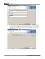
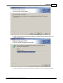
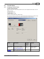
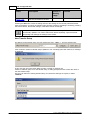
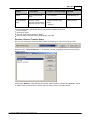
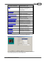
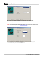
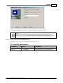
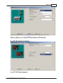
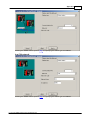
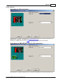
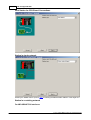
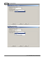
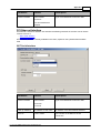
4.2
Software
...................................................................................................................................
Installation
59
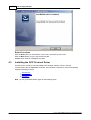
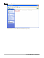
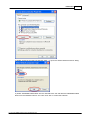
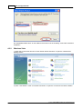
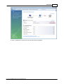
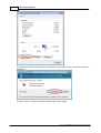
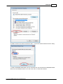
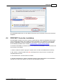
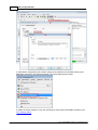
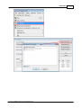
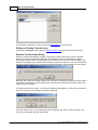
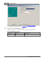
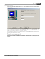
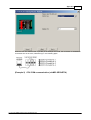
4.3
Installing
...................................................................................................................................
the DCP Protocol Driver
63
Window s XP
......................................................................................................................................................... 64
Window s Vista
......................................................................................................................................................... 67
Window s 7
......................................................................................................................................................... 71
4.3.1
4.3.2
4.3.3
4.4
PROFINET
...................................................................................................................................
Controller Installation
74
5
Getting Started
77
6
Main Menu
81
6.1
File
...................................................................................................................................
Menu
81
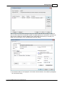
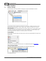
'Preview or
.........................................................................................................................................................
Print Listings' Dialog
83
6.1.1
6.2
Description
...................................................................................................................................
Menu
84
6.3
Help
...................................................................................................................................
Menu
84
7
User Interface
7.1
Device
...................................................................................................................................
Library
85
7.1.1
7.1.2
7.1.3
7.2
85
Library Menu
......................................................................................................................................................... 86
'GSDML Managem
.........................................................................................................................................................
ent' Dialog
88
'Device Type
.........................................................................................................................................................
Properties' Dialog
92
Network
...................................................................................................................................
Detection
93
'Netw ork' .........................................................................................................................................................
Menu
95
Online Action
.........................................................................................................................................................
Tool
96
7.2.1
7.2.2
7.3
PROFINET
...................................................................................................................................
Network View
101
7.3.1
7.3.2
7.3.3
'Devices'.........................................................................................................................................................
Menu
102
'Display Option'
.........................................................................................................................................................
Dialog
103
'Channel.........................................................................................................................................................
Properties' Dialog
104
(c) 2011 MITSUBISHI ELECTRIC CORPORATION
II
7.3.4
7.4
7.4.1
7.4.2
7.4.3
7.5
7.5.1
7.5.2
7.6
GX Configurator-PN
IP Address
.........................................................................................................................................................
Manager
106
Items
...................................................................................................................................
View
110
'Item s' Menu
......................................................................................................................................................... 110
'Item s Properties'
.........................................................................................................................................................
Dialog
111
'Item s Declaration'
.........................................................................................................................................................
Dialog
112
Message
...................................................................................................................................
View
116
'Message.........................................................................................................................................................
View ' Menu
116
'Message.........................................................................................................................................................
View Configuration' Dialog
117
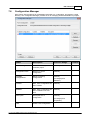
Configuration
...................................................................................................................................
Manager
118
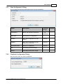
'New Configuration'
.........................................................................................................................................................
Dialog
120
'Duplicate.........................................................................................................................................................
Configuration' Dialog
120
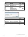
'Renam e .........................................................................................................................................................
Configuration' Dialog
121
'Configuration
.........................................................................................................................................................
Properties' Dialog
122
7.6.1
7.6.2
7.6.3
7.6.4
7.7
'ME1PN1FW-Q
...................................................................................................................................
Properties' Dialog
123
7.8
'IO-Device
...................................................................................................................................
Configuration' Dialog
124
7.8.1
7.8.2
7.8.3
7.8.4
7.8.5
7.8.6
7.9
7.9.1
7.9.2
7.10
'Device
'Device
'Device
'Device
'Device
'Device
- .........................................................................................................................................................
General Configuration' Tab
125
- .........................................................................................................................................................
Module Configuration' Tab
127
- .........................................................................................................................................................
Param eters' Tab
129
- .........................................................................................................................................................
Connection Inform ation' Tab
131
- .........................................................................................................................................................
I/O Data' Tab
133
- .........................................................................................................................................................
GSDML File' Tab
135
'Module
...................................................................................................................................
Configuration' Dialog
136
'Module Param
.........................................................................................................................................................
eters' Tab
136
'Module Inform
.........................................................................................................................................................
ation' Tab
138
'PLC
...................................................................................................................................
Settings' Dialog
139
'Update Param
.........................................................................................................................................................
eters' Dialog
144
'Multiple .........................................................................................................................................................
CPU Refresh Settings' Dialog
145
7.10.1
7.10.2
7.11
Aboutbox
................................................................................................................................... 147
8
PLC Code for PROFINET Controller
8.1
Function
...................................................................................................................................
Blocks
148
148
Function .........................................................................................................................................................
Block 'Net_Detect'
149
Function .........................................................................................................................................................
Block 'Read_Rec_Im '
152
Function .........................................................................................................................................................
Block 'Write_Rec_Ex'
154
Function .........................................................................................................................................................
Block 'Read_Rec_Ex'
155
Function .........................................................................................................................................................
Block 'Alarm _Request'
157
Function .........................................................................................................................................................
Block 'Alarm _Ack'
161
Function .........................................................................................................................................................
Block 'Alarm _Log'
163
Function .........................................................................................................................................................
Block 'IO_Device_Info'
165
8.1.1
8.1.2
8.1.3
8.1.4
8.1.5
8.1.6
8.1.7
8.1.8
8.2
Global
...................................................................................................................................
Variables
167
8.3
Integrating
...................................................................................................................................
in PLC Project
173
9
Appendix
9.1
Troubleshooting
................................................................................................................................... 177
177
Factory Default
.........................................................................................................................................................
Settings
177
9.1.1
9.2
Introduction
...................................................................................................................................
to PROFINET IO
178
9.3
Transfer
...................................................................................................................................
Setup
184
9.3.1
9.3.2
Configuring
.........................................................................................................................................................
Transfer Setups
184
Transfer .........................................................................................................................................................
Setup Wizard
188
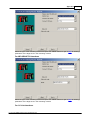
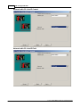
PC Universal
Serial Bus (USB) Interface
..................................................................................................................................................
192
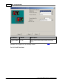
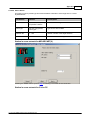
PC Universal
Serial Bus (USB) Interface via GOT
..................................................................................................................................................
193
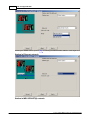
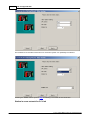
PC RS232
Serial
Interface
..................................................................................................................................................
194
(c) 2011 MITSUBISHI ELECTRIC CORPORATION
Contents
III
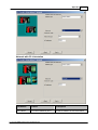
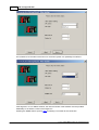
PC RS232
Serial Interface via GOT
..................................................................................................................................................
196
PC Ethernet
Board
..................................................................................................................................................
197
PC Ethernet
Board via GOT
..................................................................................................................................................
207
PC Modem
.................................................................................................................................................. 208
Modem Line
...........................................................................................................................................
Settings
209
PC CC-Link
IE Control Board
..................................................................................................................................................
218
PC MELSECNET/H
Board
..................................................................................................................................................
221
PC MELSECNET/10
Board
..................................................................................................................................................
224
PC CC-Link
IE Field Board
..................................................................................................................................................
227
PC CC-Link
Board
..................................................................................................................................................
228
PC Q Series
Bus
..................................................................................................................................................
231
PC GX Simulator
.................................................................................................................................................. 232
PC GX Simulator2
.................................................................................................................................................. 234
PC CPU Board
.................................................................................................................................................. 236
PLC CPU..................................................................................................................................................
Interface
236
PLC C24 ..................................................................................................................................................
Interface
242
PLC FX Extended
Port
..................................................................................................................................................
252
PLC Modem
.................................................................................................................................................. 257
PLC Ethernet
Interface
..................................................................................................................................................
261
PLC G4 Module
.................................................................................................................................................. 271
PLC CC-Link
IE Field Ethernet Adapter
..................................................................................................................................................
277
Netw ork .................................................................................................................................................. 286
Other Station
.................................................................................................................................................. 290
GOT Side..................................................................................................................................................
Settings
294
Enter Comment
.................................................................................................................................................. 298
9.3.3
Special Setups
......................................................................................................................................................... 299
Communication
w ith Multi-CPU Systems
..................................................................................................................................................
299
Restrictions
w ith Q00, Q00J and Q01 CPUs
..................................................................................................................................................
301
Redundant
CPUs
..................................................................................................................................................
302
Index
(c) 2011 MITSUBISHI ELECTRIC CORPORATION
311
1
1
GX Configurator-PN
How to Use
This manual...
...is a compact guide to using GX Configurator-PN software suitable both for beginners and
experienced users upgrading from other systems. The manual includes explanations of the terms
and structural concepts about the software and the configuration of an open network system. The
manual provides a precise step-by-step description of how to use GX Configurator-PN including
sample projects. The PLC series MELSEC Q Series is referenced as MELSEC system Q in this
manual.
If you are not yet familiar with MS Windows...
... please at least read the Windows Fundamentals section in the Windows User's Guide, or work
through the Windows Tutorial accessible through the Help menu of the Windows Program Manager.
This will teach you what you need to know about using the basic elements of Microsoft ® Windows,
and the operating procedures that are identical in all Windows application programs.
If you have problems with parameter settings, ...
... please refer to the user´s manuals of the concerning open network modules.
If you get stuck...
... do not despair, help is never far away! If you run up against seemingly insoluble problems, or if
you have questions about GX Configurator-PN or the connected programmable logic controller (PLC)
configuration, please first refer to the manuals and documentation. Many answers and solutions can
also be found directly in the GX Configurator-PN context-sensitive online help system, which can
always be accessed by pressing the <F1> key. If you cannot find answers to your questions in any
of these places, contact your local MITSUBISHI ELECTRIC representative or call our European
headquarters in Ratingen directly. The addresses and phone numbers are provided on the back
covers of our manuals.
(c) 2011 MITSUBISHI ELECTRIC CORPORATION
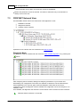
PROFINET Controller ME1PN1FW-Q
2
2
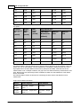
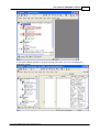
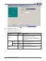
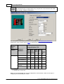
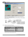
PROFINET Controller ME1PN1FW-Q
The ME1PN1FW-Q is a PROFINET RealTime (RT) communication master based on the hardware of
the Q12DCCPU-V. The restrictions of the Q12DCCPU-V with regard to environmental, mechanical
and electrical conditions apply.
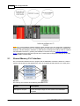
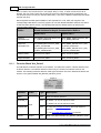
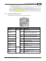
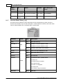
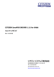
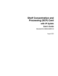
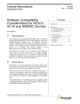
The following drawings indicate the parts of the ME1PN1FW-Q.
Front face w ith cover
closed
Front face w ith cover open
Side face
Bottom face
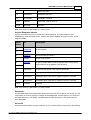
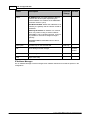
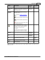
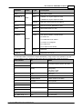
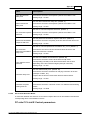
Parts list
No.
Name
Description
1
Indicator LEDs
for the USER LED see 'User LED', for the other LEDs
consult the Q12DCCPU-V manual
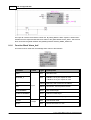
2
7-segment LEDs
see '7-Segment LED Display' for details
3
10BASE-T/100BASE-TX
interface connector (RJ45)
Ethernet interface used for configuration and PROFINET
I/O communication
(c) 2011 MITSUBISHI ELECTRIC CORPORATION
3
GX Configurator-PN
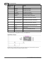
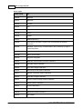
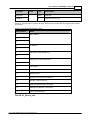
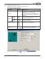
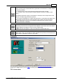
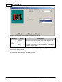
No.
Name
Description
Channel 1
4
10BASE-T/100BASE-TX
interface connector (RJ45)
Not used for the PROFINET Controller
Channel 2
5
Serial number plate
Hardware serial number
6
EJECT button
Press to eject CF card from slot
7
CompactFlash (CF) card
installation slot
Slot for installing CF card
8
RUN/STOP/MODE switch
Sets the operation mode
9
RESET/SELECT switch
Used to reset the module
10
USB interface connector
For USB connections
Not supported by the PROFINET Controller. The module
can only be accessed via the first Ethernet port.
11
Battery
Buffers data in RAM
12
Battery connector pin
Pin to connect battery
Note: when delivered the battery is not connected to
ensure its capacity.
13
RS-232 interface
connector
For RS-232 connections
Not supported by the PROFINET Controller.
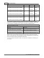
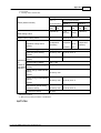
Technical Data
Maximum number of total cyclic
input data (1)
9228 bytes
Maximum number of total cyclic
output data (1)
9900 bytes
Maximum number of cyclic input
data
1437 bytes per device (= IOCR data length)
Maximum number of cyclic
output data
1437 bytes per device (= IOCR data length)
Maximum number of configured
devices
128
Minimum cycle time
1 ms
(c) 2011 MITSUBISHI ELECTRIC CORPORATION
PROFINET Controller ME1PN1FW-Q
Maximum number of total cyclic
input data (1)
9228 bytes
Maximum cycle time
512 ms
4
Different IO-Devices can be configured with different
cycle times
RT communication
RT Class 1
Alarm processing
Read/Write Records
Limited to 5448 bytes per request
DCP (Discovery & Configure
Protocol)
Supported
RPC (Remote Procedure Call)
Supported (up to 4 fragments 5448 bytes)
Baud rate
100 MBit/s Full-Duplex mode
Data transport layer
Ethernet II, IEEE 802.3
LLDP sender
supported
(1) these sizes includes potential padding that could be inserted for variable alignment.
The following limitations apply:
The usable (minimum) cycle time depends on the number of IO-devices and the total size of input
and output data. For example it is not possible due to performance reasons to have 128 IOdevices communicating with a cycle-time of 1 ms.
RT over UDP, RT Class 2 and RT Class 3 (IRT) are not supported
Multicast communication is not supported
DHCP is not supported (neither for the PROFINET Controller nor for the IO-devices)
Only one input IOCR and one output IOCR per IO-device
Only one API (API = 0) is supported. Any profile requesting a different API is currently not
supported.
The IO-device feature “FastStartUp” cannot be used
WriteMultiple-Record service is not supported
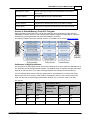
System Configuration
The ME1PN1FW-Q uses high speed data transfer for the data exchange with the controlling CPU. It
can only be used in combination with QnUD(E)-CPUs, which support high speed data transfer. The
following QnUD-CPUs do not support high speed transfer and therefore cannot be used
Q00UJ
Q00U
Q01U
Q02U
Mounting the PROFINET Controller in a PLC Rack
The PROFINET Controller must be placed in the first slot next to the controlling Qn-CPU. Additional
intelligent and I/O modules are supported in the slots following the PROFINET Controller, where they
can be accessed by the controlling Qn-CPU. Additional CPUs are not supported.
(c) 2011 MITSUBISHI ELECTRIC CORPORATION
5
GX Configurator-PN
Note: if any of the intelligent modules requires specific settings in the 'I/O Assignment' configuration,
these settings must first be set in the controlling Qn-CPU using the PLC programming software (GX
Developer, GX IEC Developer, GX Works 2). After this the I/O assignment settings must be copied to
the PROFINET Controller by updating the PROFINET Controller using the 'Update Parameters'
dialog. Otherwise the Qn-CPU will signal an error, because the I/O assignment settings on Qn-CPU
and PROFINET Controller differ.
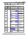
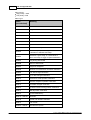
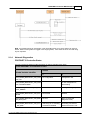
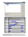
2.1
Shared Memory PLC Interface
The communication between the PLC program and the PROFINET Controller is based on a shared
memory area (inside the High Speed Area), which is accessed via buffer devices in the CPU (PLC).
The memory area consists of the following sections
Block
Description
Management Outputs
Control and request flags from the Q-CPU to the PROFINET
Controller
(c) 2011 MITSUBISHI ELECTRIC CORPORATION
PROFINET Controller ME1PN1FW-Q
Management Inputs
Status and response flags from the PROFINET Controller to
the Q-CPU
Acyclic Outputs
Request buffer for acyclic communication
Acyclic Inputs
Response buffer for acyclic communication
Cyclic Outputs
Outputs for I/O devices sent during cyclic data exchange
Cyclic Inputs
Inputs from I/O devices received during cyclic data exchange
6
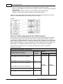
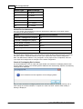
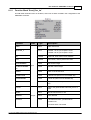
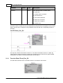
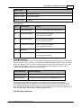
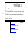
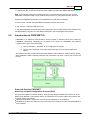
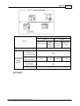
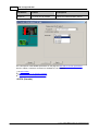
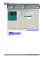
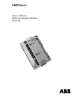
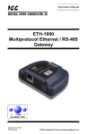
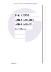
Access to Shared Memory From PLC Program
GX Configurator-PN generates PLC code for the interaction of the application program with the
PROFINET Controller. The PLC code contains global variables mapped to buffer devices, which are
automatically exchanged between Qn-CPU and PROFINET Controller.
The following diagram shows the principal structure. For details see the section 'Global Variables'.
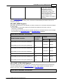
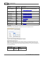
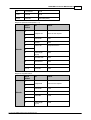
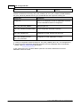
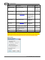
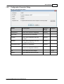
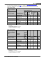
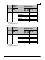
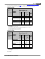
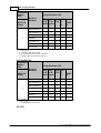
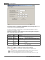
Addresses in High Speed Area
The settings for the high speed transfer in both the controlling Qn-CPU as well as the ME1PN1FW-Q
are updated by the GX Configurator-PN software. The address range occupied in the high speed area
depends on the size of the cyclic data exchanged between the controller and the I/O devices.
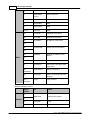
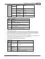
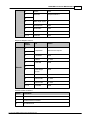
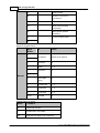
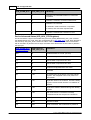
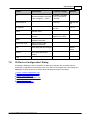
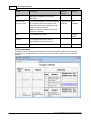
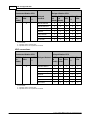
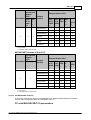
The two following tables list the used high speed memory area addresses for outputs and inputs.
Because the size of the memory areas used for management and for acyclic communication are
fixed, the total size of required high speed buffers depends only on the size of the cyclic data.
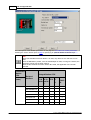
For outputs:
Profinet
manageme
nt
Acyclic
Buffer
Size
(words)
(words)
Max
Cyclic
Output
Size
(words)
High Speed Area
Calculated
Minimal Size
Address
Start
Address
End
(kWords)
N/A
N/A
N/A
0
N/A
N/A
N/A
N/A
N/A
1
N/A
N/A
N/A
N/A
N/A
2
N/A
N/A
(c) 2011 MITSUBISHI ELECTRIC CORPORATION
7
GX Configurator-PN
118
2100
854
3
10 000
13071
118
2100
1878
4
10 000
14095
118
2100
2902
5
10 000
15119
118
2100
3926
6
10 000
16143
118
2100
4950
7
10 000
17167
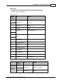
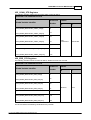
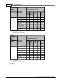
Profinet
manageme
nt
Acyclic
Buffer
Size
High Speed Area
(words)
(words)
Max
Input
Size
(words)
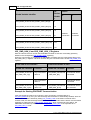
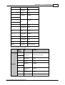
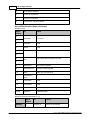
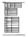
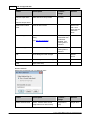
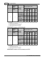
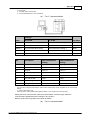
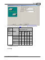
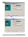
For inputs:
Calculated
Minimal Size
Address
Start
Address
End
(kWords)
N/A
N/A
N/A
0
N/A
N/A
N/A
N/A
N/A
1
N/A
N/A
N/A
N/A
N/A
2
N/A
N/A
112
2442
518
3
10 000
13071
112
2442
1542
4
10 000
14095
112
2442
2566
5
10 000
15119
112
2442
3590
6
10 000
16143
112
2442
4614
7
10 000
17167
The refresh buffers in the high speed memory area are always aligned to the end address of the high
speed area, not its start address. The end addresses is calculated by adding the total size of the
high speed area to the start address of the memory area (here 0x10000). If the total size of the
refresh buffers is not a multiple of kWords, the gap to the next kWord boundary is filled with the 'user
area'. Because the user area always starts at address 0x10000, the start addresses of the refresh
blocks are variable.
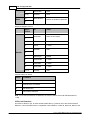
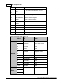
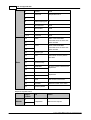
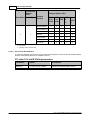
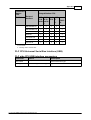
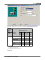
The following tables contain the formulas for calculating the start and the end address of each
refresh block.
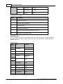
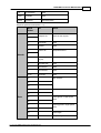
Output Areas Offsets Calculation
Block
Start Address
End Address
Cyclic
Outputs
End Addr. - Output
size + 1
End Addr.
Acyclic
Outputs
End Addr. - Output size 2100 + 1
End Addr. - Output
size
(c) 2011 MITSUBISHI ELECTRIC CORPORATION
PROFINET Controller ME1PN1FW-Q
Mgmt.
Outputs
End Addr. - Output size 2100 - 118 + 1
8
End Addr. - Output
size - 2100
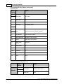
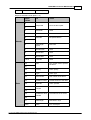
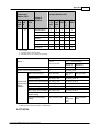
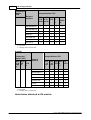
Input Areas Offset Calculation
Block
Start Address
End Address
Cyclic
Inputs
End Addr. - Input size +
1
End Addr.
Acyclic
Inputs
End Addr. - Input size 2442 + 1
End Addr. - Input
size
Mgmt.
Inputs
End Addr. - Input size 2442 - 112 + 1
End Addr. - Input
size - 2442
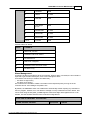
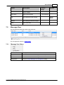
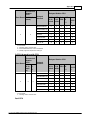
Two examples show the application of these formulas for calculating the start and end addresses for
a specific combination output and input size, resulting from the corresponding PROFINET
configuration.
Example 1: Output size is 900 and Input size is 500.
Addresses in high speed area
Size in
word
Nb
points
(K)
start
end
I/O
Acyclic
Buffer
PROFINET
Management
Outputs
900
4
10000
14095
1319614095
1109613195
10978-11095
Inputs
500
3
10000
13071
1257213071
1027212371
10160-10271
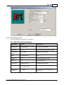
Example 2: Output size is 1900 and Input size is 1900.
Addresses in high speed area
Size in
word
Nb
points
(K)
start
end
I/O
Acyclic
Buffer
PROFINET
Management
Outputs
1900
5
10000
15119
1319614095
1109613195
10978-11095
Inputs
1900
5
10000
15119
1237213071
1027212371
10160-10271
Shared Memory Structure
Data from Qn-CPU to PROFINET Controller
Size
in
Word
Block
number
(for PLC)
Global Variable Identifiers
in Exported PLC Code
(c) 2011 MITSUBISHI ELECTRIC CORPORATION
Description
9
GX Configurator-PN
High Speed Transmission Area (0x2710 – 0x5F0F)
vPN_MGMT_OUTPUTS.IOC_ST
1
ART_STOP
vPN_MGMT_OUTPUTS.IOD_M
GT_MODE
8
vPN_MGMT_OUTPUTS.IOD_ST
ART_STOP_DEV
8
vPN_MGMT_OUTPUTS.IOD_C
MD_HSK_Y
8
vPN_MGMT_OUTPUTS.IOD_M
GT_ALARM
8
BLOCK 1
Size: 118
vPN_MGMT_OUTPUTS.IOD_C
ONSIST
8
vPN_MGMT_OUTPUTS.IOD_IN
PUT_HSK_Y
8
vPN_MGMT_OUTPUTS.IOD_O
UTPUT_HSK_Y
8
vPN_MGMT_OUTPUTS.ACYC_
HSK_Y_REQ1_EXECUTE and
ACYC_HSK_Y_REQ2_EXECUTE
1
Allows to start or stop the
PROFINET IO-Controller.
Allow to set IO-Device
management in automatic
or manual mode.
Allow to connect or
release connection with an
IO-Device.
PLC to PROFINET
Controller handshake flag
to perform command
indicated in
IOD_START_STOP_DEV
Allow to enable or disable
alarm management by
PLC
Allow to enable or disable
the handshake
mechanism for I/O data
(so having consistency
enabled)
PLC to PROFINET
Controller handshake flags
for Inputs
PLC to PROFINET
Controller handshake flags
for Outputs
PLC to PROFINET
Controller handshake bits
for acyclic requests (2 bits
used)
60
Reserved
Reserved for future use
750
vPN_ACYCLIC_REQ1
vPN_ACYCLIC_REQ2
Buffers for acyclic request
data (2 buffers - max 1500
bytes each incl. header)
600
Reserved
Reserved
1
BLOCK 3
vPN_CYCLIC_OUTPUTS.LIVE_W
ORD_Y
PLC to PROFINET
Controller live register
Size: 4950
max
variable names for cyclic I/O data
are user-defined
output data sent to IODevices. The data size is
BLOCK 2
750
Variable
,
Size: 2100
(c) 2011 MITSUBISHI ELECTRIC CORPORATION
PROFINET Controller ME1PN1FW-Q
Up to
4949
variable up to 9898 bytes.
Data from PROFINET Controller to Qn-CPU
Size
in
Word
Block
number
(for PLC)
Global Variable Identifier
Description
High Speed Transmission Area (0x2710 – 0x5F0F)
vPN_MGMT_INPUTS.IOC_STS_
2
IO Controller Status
*
vPN_MGMT_INPUTS.IOD_CMD_ PROFINET Controller to
8
HSK_X
PLC handshake flag to
acknowledge command in
IOD_START_STOP_DEV
vPN_MGMT_INPUTS.IOD_INPU
PROFINET Controller to
PLC handshake flags for
Inputs
T_HSK_X
8
vPN_MGMT_INPUTS.IOD_OUTP
UT_HSK_X
8
BLOCK 1
1
vPN_MGMT_INPUTS.ACYC_HS
K_X_*
Size: 112
vPN_MGMT_INPUTS.IOD_ALAR
8
PROFINET Controller to
PLC handshake bits for
acyclic requests (2 bits
used)
Alarm indication
M_IND
vPN_MGMT_INPUTS.IOD_CON
N_STS
8
vPN_MGMT_INPUTS.IOD_ERR_
STS
8
61
Reserved
750
vPN_ACYCLIC_RES1
750
PROFINET Controller to
PLC handshake flags for
Outputs
BLOCK 2
vPN_ACYCLIC_RES2
Connection status flag
0: IO-device Not
connected
1 Device connected
Device ERROR flag
0: device no error
1 Device in error
Buffers for acyclic request
answer (2 buffers - max
1500 bytes each incl.
header)
Size 2442
20
vPN_ACYCLIC_DIAG_INPUTS.AD
V_DIAG_*
(c) 2011 MITSUBISHI ELECTRIC CORPORATION
Advanced diagnostic
information about issues
10
11
GX Configurator-PN
with PROFINET
256
Reserved for future time stamping
Not Used. Reserved
2
vPN_ACYCLIC_DIAG_INPUTS.CN
F_CRC
Configuration CRC value.
vPN_ACYCLIC_DIAG_INPUTS.IO
D_ADV_STS
Advanced device status
1 : Never Connected
0: Connected
2: Disconnected
64
3: Connected in error
(IOPS/IOCS/APDU
STATUS in error state)
4: time Out
600
1
Up to
4677
2.1.1
Reserved
BLOCK 3
vPN_CYCLIC_INPUTS.LIFE_WOR
D_X
PROFINET Controller to
PLC live register
Size 4678
max
variable names for cyclic I/O data
are user-defined
Input data received from
each IO-Device. Size up to
9345 bytes.
Management Area
IOC_START_STOP Register
This register is set or cleared by the control CPU to start or stop the PROFINET Controller.
From CPU to PROFINET IO-Controller
Values
Global Var. Identifier
vPN_MGMT_OUTPUTS.IOC_
START_STOP
0
1
IO-controller has to be stopped
IO-controller has to be started
If the IO-controller is not
started, nothing is done by
PROFINET firmware.
If the IO-controller is started,
nothing is done by PROFINET
firmware.
If the IO-controller is starting or
started, each connection will
be automatically released by
the firmware, even if the
connection is in manual
management.
If the IO-controller is stopping
(stop sequence), the firmware
will continue the stop
sequence up to the end and
then will initiate again a start
sequence.
If the IO-controller is stopped,
the IO-controller will be
started. The controller will try
(c) 2011 MITSUBISHI ELECTRIC CORPORATION
PROFINET Controller ME1PN1FW-Q
12
to start each connection with
an IO-device, which is
configured with automatic
management mode(1). Each
connection with a device in
manual management mode will
not be up until the PLC
explicitly sends a command to
the device.
(1) See IOD_MGT_MODE registers. By default the IO-device management is in automatic mode
(bits are 0). If the PLC does nothing, every connection will automatically be started, when the IOcontroller is started.
IOD_MGT_MODE Registers
With these 128 bits the PLC can indicate, how each connection to an IO-device should be managed
by the firmware.
- for an IO-device in automatic mode the IO-controller will initiate the connection, until the
connection is established.
- for an IO-device in manual mode the IO-controller will wait for commands from the PLC to manage
the connection (see IOD_START_STOP and IOD_CMD_HSK_Y registers).
From CPU to PROFINET IO-Controller
IO-Device
Global Variable Identifier
Number
Values
0
1
Manual
..
vPN_MGMT_OUTPUTS.IOD_MGT_MODE[0]
0
Automatic
…
..
vPN_MGMT_OUTPUTS.IOD_MGT_MODE[15]
15
..
Automatic
vPN_MGMT_OUTPUTS.IOD_MGT_MODE[16]
16
Automatic
…
..
vPN_MGMT_OUTPUTS.IOD_MGT_MODE[31]
31
..
Automatic
…
…
…
…
vPN_MGMT_OUTPUTS.IOD_MGT_MODE[116]
116
Automatic
…
..
vPN_MGMT_OUTPUTS.IOD_MGT_MODE[127]
127
..
Automatic
Manual
..
Manual
Manual
..
Manual
Manual
IOD_START_STOP_DEV Registers
With these 128 bits the PLC specifies, which command will be executed when the corresponding
command handshake flag (see IOD_CMD_HSK_Y) is set. These registers are relevant only for
devices, which are in manual management mode (see IOD_MGT_MODE).
From CPU to PROFINET IO-Controller
(c) 2011 MITSUBISHI ELECTRIC CORPORATION
13
GX Configurator-PN
IODevice
Global Variable Identifier
Numbe
r
vPN_MGMT_OUTPUTS.IOD_START_STOP_DEV[0]
0
…
..
vPN_MGMT_OUTPUTS.IOD_START_STOP_DEV[15]
15
vPN_MGMT_OUTPUTS.IOD_START_STOP_DEV[16]
16
…
..
vPN_MGMT_OUTPUTS.IOD_START_STOP_DEV[31]
31
…
…
vPN_MGMT_OUTPUTS.IOD_START_STOP_DEV[116]
116
…
..
vPN_MGMT_OUTPUTS.IOD_START_STOP_DEV[127]
127
Values
0
1
Release
connection
Establish
connection
IOD_CMD_HSK_X and IOD_CMD_HSK_Y Registers
With the 128 bits the PLC can ask the PROFINET Controller to execute command(s) previously
defined in the corresponding IOD_START_STOP register(s).
When the command(s) are completed, the PROFINET Controller sets the corresponding bit(s) in the
IOD_CMD_HSK_Y registers. The PLC can then verify the connection status via the IOD_CONN_STS
registers.
From CPU to IO-Controller
From IO-Controller to CPU
Global Var. Identifier
Function
Global Var. Identifier
Function
vPN_MGMT_OUTPUTS.I
OD_CMD_HSK_Y[0]
Trig command for
device 0
vPN_MGMT_INPUTS.IOD
_CMD_HSK_X[0]
command for device
0 executed
…
Trig command for
device n
…
command for device
n executed
vPN_MGMT_OUTPUTS.I
OD_CMD_HSK_Y[127]
Trig command for
device 127
vPN_MGMT_INPUTS.IOD
_CMD_HSK_X[127]
command for device
127 executed
Example for Starting PROFINET Communication
If the data exchange mode for an IO device is set to 'automatic' (corresponding bit in
IOD_MGT_MODE is 0), the cyclic data exchange with the device is automatically initiated, when the
PROFINET Controller is started by setting IOC_START_STOP. If the device is however set to
'manual' mode, the data exchange between the PROFINET Controller and the device must be started
separately by setting the bit in IOD_START_STOP_DEV, which corresponds to the device. The
PROFINET Controller only evaluates a bit in IOD_START_STOP_DEV, if the equivalent bit in
IOD_CMD_HSK_Y is set.
(c) 2011 MITSUBISHI ELECTRIC CORPORATION
PROFINET Controller ME1PN1FW-Q
2.1.2
14
Cyclic Communication Area
Process Data (Cyclic Data Exchange)
From the PROFINET perspective the cyclic communication is a continuous transfer of input and
output data between the IO-controller and each IO-device without further interaction by the
application. In PROFINET the cyclic communication is based on the producer/consumer model. For
each IO-device, the IO-controller establishes connection with a specific refresh period (duration of the
cycle). The cyclic data exchange can be individually started or stopped for each PROFINET IOdevice.
Inputs and outputs are exchanged between the PLC and the PROFINET Controller via the
INPUT_DATA and OUTPUT DATA buffers.
- I/O variables configured in GX Configurator-PN are located inside these two buffers by respecting
some alignment rules.
- As these buffers can be accessed simultaneously from the PROFINET Controller and the PLC, a
handshake mechanism exists to ensure consistency on all variables. This mechanism is optional
and can be activated and deactivated per device.
Input and Output Data Alignment
The IO-device input and output areas in the buffer memory of the PROFINET Controller are wordaligned. PROFINET variables are located in the shared memory by respecting the following rules
The data of each PROFINET IO-device is placed at an address on a word boundary, independent
of its type.
Single or array variables must be aligned on an address modulo of the minimum of both the PLC
alignment (2) and the native type size (1, 2 or 4). So specifically
(c) 2011 MITSUBISHI ELECTRIC CORPORATION
15
GX Configurator-PN
o Each slot should always be located at the next available word boundary address
o BYTEs or BYTE ARRAYS of the same slot are packed in memory to follow directly the previous
defined variable
o WORDs should always be located at the next available word boundary address
o DWORDs, FLOATs should be also located at a word boundary address
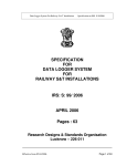
Additionally all WORD, DWORD and FLOAT variables are stored in little-endian format in shared
memory, to ease interpretation of the variables by the PLC program.
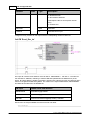
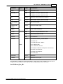
Example:
IO-Device Consistency Management (IOD_CONSIST Registers)
The Q-series OS can ensure data consistency within a word in the data exchange via Autorefresh.
The Autorefresh settings of the respective module contain a module specific X-device, which the
communication module resets during access to the buffer memory. The CPU must check this device
before accessing the buffer memory. If consistency handling has been disabled in the module, the
device remains permanently set. The single X-device can only control access to the I/O data of all
slaves together. An individual handshake for each station is not possible with this approach.
Using the following 128 bits the PLC can enable and disable at any time the consistency
management per device.
From CPU to PROFINET IO-Controller
IO-Device
Global Variable Identifiers
Number
vPN_MGMT_OUTPUTS.IOD_CONSIST[0]
0
…
..
vPN_MGMT_OUTPUTS.IOD_CONSIST[15]
15
vPN_MGMT_OUTPUTS.IOD_CONSIST[16]
16
…
..
vPN_MGMT_OUTPUTS.IOD_CONSIST[31]
31
…
…
vPN_MGMT_OUTPUTS.IOD_CONSIST[116]
116
…
..
Values
0 (default)
1
Disable
Consistency
Enable
Consistency
(c) 2011 MITSUBISHI ELECTRIC CORPORATION
PROFINET Controller ME1PN1FW-Q
vPN_MGMT_OUTPUTS.IOD_CONSIST[127]
16
127
Therefore station-specific handshake flags are added to the shared memory, which block
simultaneous access to the same input or output area by both the master and the PLC program.
This solution is slower, but has the following advantages:
1. IO-controller checks the configuration to detect stations, which require consistency
2. it marks those stations, which require consistency for inputs and outputs.
3. handshake controls access to each station separately, not blocking simultaneous access to all
stations
The disadvantage of this solution is the delay between two updates data from PLC.
Note: PLC CPU and PROFINET Controller cannot write to the same area in shared memory.
Therefore the handshake mechanism requires to define two bits for device inputs and two bits for
device outputs.
Output Handshake Registers (IOD_OUTPUT_HSK_Y and
IOD_OUTPUT_HSK_X)
From CPU to IO-Controller
Global Variable Identifier
Function
vPN_MGMT_OUTPUTS.IOD_OUTPUT_HSK_Y[0]
Take into account new outputs for
device 0
…
Take into account new outputs for
device n
vPN_MGMT_OUTPUTS.IOD_OUTPUT_HSK_Y[127]
Take into account new outputs for
device 127
From IO-Controller to CPU
Global Variable Identifier
Function
vPN_MGMT_INPUTS.IOD_OUTPUT_HSK_X[0]
New Outputs read (will be sent to the
IO-device 0 during next exchange)
…
New Outputs read (will be sent to the
IO-device n during next exchange)
vPN_MGMT_INPUTS.IOD_OUTPUT_HSK_X[127]
New Outputs read (will be sent to the
IO-device 127 during next exchange)
Input Handshake Registers (IOD_INPUT_HSK_Y and IOD_INPUT_HSK_X)
From CPU to IO-Controller
(c) 2011 MITSUBISHI ELECTRIC CORPORATION
17
GX Configurator-PN
Global Variable Identifier
Function
vPN_MGMT_OUTPUTS.IOD_INPUT_HSK_Y[0]
New Inputs of the IO-device 0 has
been read.
…
New Inputs of the IO-device n has
been read.
vPN_MGMT_OUTPUTS.IOD_INPUT_HSK_Y[127]
New Inputs of the IO-device 127 has
been read.
From IO-Controller to CPU
Global Variable Identifier
Function
vPN_MGMT_INPUTS.IOD_INPUT_HSK_X[0]
Take in account new inputs from
device 0
…
Takes in account new input from
device n
vPN_MGMT_INPUTS.IOD_INPUT_HSK_X[127]
Takes in account new input from
device 127
Note: the ‘Input/output PLC-side flags’ are set and cleared by the PLC program, the ‘Input/output
master-side flags’ are set and cleared by the master. In general write access is permitted to the
input or output area of a station, if both flags are equal (0 ,0 or 1,1). Read access is permitted if both
flags differ (0 ,1 or 1, 0).
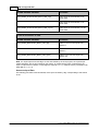
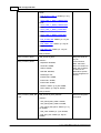
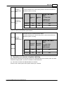
Access to Input Data
The following procedure must be followed, if the ‘Input consistency flag’ corresponding to the station
is set.
(c) 2011 MITSUBISHI ELECTRIC CORPORATION
PROFINET Controller ME1PN1FW-Q
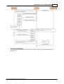
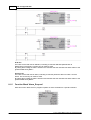
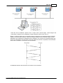
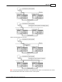
Access to Output Data
The following procedure must be followed, if the ‘Output consistency flag’ corresponding to the
station is set.
(c) 2011 MITSUBISHI ELECTRIC CORPORATION
18
19
GX Configurator-PN
Cycle 1:
1. The PLC CPU detects that the output buffer is free because values of the handshake flags are
equal (0:0 for cycle 1)
2. The PLC CPU writes the output data to the OUTPUT_DATA buffer
3. The PLC CPU toggles its handshake flag (0 -> 1 for cycle 1)
4. The PROFINET Controller detects that the values of the handshake flags are different
5. The PROFINET Controller reads the output data from the OUTPUT_DATA buffer
6. The PROFINET Controller signals that the output buffer is free by toggling its bit to equal the one
of the PLC CPU (0 -> 1 for cycle 1)
7. The cycle 1 is completed
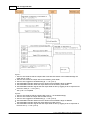
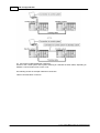
Cycle 2:
1. The PLC CPU detects that the output buffer is free (1:1 in handshake flags)
2. The PLC CPU writes the output data to buffer memory
3. The PLC CPU toggles its handshake flag (1 -> 0 for cycle 2)
4. The PROFINET Controller detects that the values of the handshake flags are different
5. The PROFINET Controller reads the output data from buffer memory
6. The PROFINET Controller signals that the output buffer is free by toggling its bit to equal that of
the PLC CPU (1 -> 0 for cycle 2)
(c) 2011 MITSUBISHI ELECTRIC CORPORATION
PROFINET Controller ME1PN1FW-Q
20
7. The cycle 2 is completed
2.1.3
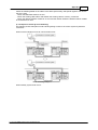
Acyclic Communication Area
The acyclic communication is an exchange of request and response messages between the
PROFINET Controller and each IO-device station. The message exchange must be initiated by the
controller.
Acyclic Request/Response Buffers
The shared memory area contains two pairs of buffers (vPN_ACYCLIC_REQ1/2 and
vPN_ACYCLIC_RES1/2) allowing two acyclic requests to be performed simultaneously.:
- vPN_ACYCLIC_REQ1 and vPN_ACYCLIC_REQ2 allow PLC to deposit a request.
- vPN_ACYCLIC_RES1 and vPN_ACYCLIC_RES2 allows to get the respective answers
To manage synchronization, some handshake bits are used. A request buffer can be used to send a
request to any of the configured stations; there is no relation between a request buffer and a
particular station.
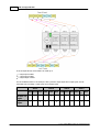
Acyclic Handshake Bits
Each request/response buffer pair is associated with a set of handshake bits.
Global Variable Identifier
Description
vPN_MGMT_OUTPUTS.ACYC_HSK_Y_RE
Q1_EXECUTE
execution req. flag for buffer 1
vPN_MGMT_OUTPUTS.ACYC_HSK_Y_RE
Q2_EXECUTE
execution req. flag for buffer 2
vPN_MGMT_INPUTS.ACYC_HSK_X_RES1
_COMPLETED
request in buffer 1 completed,
response is in corresponding buffer
vPN_MGMT_INPUTS.ACYC_HSK_X_RES2
_COMPLETED
request in buffer 2 completed,
response is in corresponding buffer
vPN_MGMT_INPUTS.ACYC_HSK_X_RES1
_ACCEPTED
request in buffer 1 accepted
vPN_MGMT_INPUTS.ACYC_HSK_X_RES2
_ACCEPTED
request in buffer 2 accepted
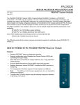
Once the response has been read by the PLC from the response buffer, the PLC must clear the
ACYC_HSK_Y_REQ<n>_EXECUTE bit corresponding to the request. The PROFINET Controller will
then clear the two corresponding bits ACYC_HSK_X_RES<n>_ACCEPTED and
ACYC_HSK_X_RES<n>_COMPLETED.
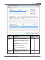
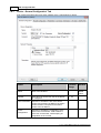
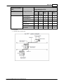
The following diagram shows the request/response handshake between PLC program and the
PROFINET Controller for acyclic communication.
(c) 2011 MITSUBISHI ELECTRIC CORPORATION
21
GX Configurator-PN
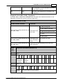
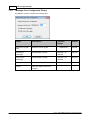
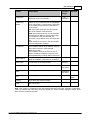
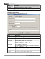
Acyclic Request Header
The request buffer consists of an header and a data buffer area. The same header is used whatever
is the requested service. Consult each service detailed description to verify which fields are relevant.
Word
Offset
ID
Description
RequestID
ID of the request
2
ServiceID
service identifier (see above)
3
Status
Status of the request. shall always be equal to 0x55.
DeviceID
IO-Device number defined in the GX Configurator PN, or in the
case of implicit request, the IP address of the IO-device.
0
1
4
5
6
API number used to perform the Read
API
7
8
SlotNumber
Value: 0 to 0xFFFFFFFF
Target slot number.
Value: 0 to 0x7FFF
9
SubslotNumber
Target subslot numbe
Value: 1 to 0x8FFF
10
Index
Index in the slot or sub-slot
Value: 1 to 0xFFFF
11
Data length (byte)
Number of bytes stored in the request data buffer
(c) 2011 MITSUBISHI ELECTRIC CORPORATION
PROFINET Controller ME1PN1FW-Q
22
Value: 0 to 1440.
12
PnDeviceID
PROFINET Device ID
13
PnVendorID
PROFINET Vendor ID
14-21
ARUUID
Never used, must be set to 0.
22-29
Reserved
Reserved
Note: Each value is in little-endian- (i.e. Intel-) format.
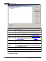
Acyclic Response Header
The response buffer consists of a header and a data buffer area. The same header is used
independently of the requested service. Consult each service detailed description to verify, which
fields are relevant.
Word
Offset
ID
Description
RequestID
ID of the request
2
ServiceID
service identifier (see above)
3
Status
Status of the Request
4
DeviceID
IO-device number defined in GX Configurator-PN or in the case of
explicit request, the IP address of the IO-device.
6
Data length
Number of bytes stored in the response data buffer
7
ErrorDecode
PROFINET value. Used when a negative response is returned
8
ErrorCode1
PROFINET value. Used when a negative response is returned
9
ErrorCode2
PROFINET value. Used when a negative response is returned
10-19
reserved
Reserved
0
1
5
Note: Each value is in little-endian- (i.e. Intel-) format.
RequestID
The RequestID field in the request buffer header can be used by PLC to identify the answer. It is the
responsibility of the PLC program to manage the field RequestID. The best practice is to increment
this field before each new request. The PROFINET firmware will answer to the request with the
same RequestID.
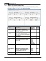
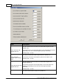
ServiceID
The field 'ServiceID' marks the type of request. Acyclic communication can be used for the following
(c) 2011 MITSUBISHI ELECTRIC CORPORATION
23
GX Configurator-PN
services:
Service
Identifier
Description
Network detection
0x01
determines the number of connected IO devices
(see 'Network Detection Service')
IO-Device Detected
0x02
Read Implicit
0x03
see 'Record Block Implicit Read'
Write Explicit
0x04
see 'Record Block Explicit Write'
Read Explicit
0x05
see 'Record Block Explicit Read'
Alarm Request
0x06
see 'Alarm Request'
Alarm Ack
0x07
see 'Alarm Ack'
IO-Device Information
0x08
get information for a specific IO device
Read alarm log
0x09
see 'Alarm Log'
DeviceID
This ID is defined during PROFINET configuration with the GX Configurator PN tool.
Acyclic Service Request/Response Formats
Network Detection Service
Based on DCP identify request, this service allows to detect up to 255 IO-devices present on the
network (LAN). This function returns only the number of IO-Devices detected. After the call of this
service, it is needed to call the service IO-Device detected (serviceID = 2) to get more information on
each detected IO-Device.
Request Format
Word Offset
ID
Value
0
RequestID
PLC value
(c) 2011 MITSUBISHI ELECTRIC CORPORATION
PROFINET Controller ME1PN1FW-Q
1
2
ServiceID
0x01
3
Status
0x55
4
DeviceID
0x0000
5
6
0x0000
API
7
8
SlotNumber
0x00
9
SubslotNum
ber
0x00
10
Index
0x00
11
Data length
(byte)
0x0000
12
PnDeviceID
0x00
13
PnVendorID
0x00
14-21
ARUUID
0x00
22-29
Reserved
Reserved (0x00)
Response Positive Format (Status = 0)
Word
Offset
ID
Value
RequestID
Same as the request
2
ServiceID
0x01
3
Status
0x00
4
DeviceID
0x0000
6
Data length
(byte)
0x0004
7
ErrorDecode
0x00
8
ErrorCode1
0x00
0
1
Header
5
(c) 2011 MITSUBISHI ELECTRIC CORPORATION
24
25
GX Configurator-PN
9
ErrorCode2
0x00
10-19
reserved
0x00
20
Nb IO-Devices
Data
Number of IO-devices detected
21
Response Negative Format
Word
Offset
ID
Value
RequestID
Same as the request
2
ServiceID
0x01
3
Status
!= 0x00
4
DeviceID
0x00
6
Data length
0x0000
7
ErrorDecode
!= 0x00
8
ErrorCode1
!= 0x00
9
ErrorCode2
!= 0x00
10-19
reserved
0x00
0
1
Header
5
Possible values for Status
Value
Comment
0
Status OK
1
Profinet stack not started
2
No ethernet link
3
No IO-Device detected
Note: if more than 255 devices are detected, the function returns status OK and NbIO Devices
==255
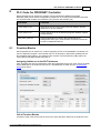
IO-Device Detection
This function allows to get ,for each IO-Device detected by a previous call to the service Network
Detection, some information like IP configuration, MAC Address, Vendor ID, Device ID, Name of the
(c) 2011 MITSUBISHI ELECTRIC CORPORATION
PROFINET Controller ME1PN1FW-Q
IO-Device and IO-Device type.
Request format
Word
Offset
ID
Value
RequestID
PLC value
2
ServiceID
0x02
3
Status
0x55
4
DeviceID
0x0000
0
1
5
6
0x0000
API
7
8
slot_number
0x00
9
Subslot_number
0x00
10
Index
0x00
11
Data length (byte)
0x00
12
PnDeviceID
0x00
13
PnVendorID
0x00
14-21
ARUUID
0x00
22-29
Reserved
Reserved (0x00)
Response Positive Format (Status = 0)
Word
Offset
ID
Value
RequestID
Same as the request
2
ServiceID
0x02
3
Status
0x00
4
DeviceID
0x0000
0
1
Header
(c) 2011 MITSUBISHI ELECTRIC CORPORATION
26
27
GX Configurator-PN
5
6
Data length
(byte)
Size of the Data.
7
ErrorDecode
0x00
8
ErrorCode1
0x00
9
ErrorCode2
0x00
10-19
reserved
0x00
20
VendorID
VendorID of the device
21
DeviceID
DeviceID of the device
22
IP address
IP address of the Device
Subnetmask
Subnet mask of the Device
Gateway
Gateway IP Address of the
Device
28 – 30
Mac address
Mac Address of the Device
31
SizeName
Size name of the device (240
bytes max)
32 SizeName
DeviceName
Name of the device
XX
SizeType
Size of “Type” field (max size :
25 byte)
Xx+1 –
SizeType
Type
Type of Device
23
24
25
26
Data
27
Response Negative Format
Word
Offset
ID
Value
RequestID
Same as the request
2
ServiceID
0x02
3
Status
!= 0x00
0
1
Header
(c) 2011 MITSUBISHI ELECTRIC CORPORATION
PROFINET Controller ME1PN1FW-Q
4
DeviceID
0x0000
6
Data length (byte)
0x00
7
ErrorDecode
!= 0x00
8
ErrorCode1
!= 0x00
9
ErrorCode2
!= 0x00
10-19
Reserved
0x00
28
5
Possible Values for Status
Value
Comment
0
Status OK
1
Profinet stack not started
4
Reception buffer too small (stack internal error)
5
No more IO-Device
6
“Network detection” service never called.
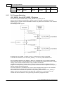
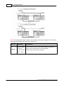
Network Detection Scenario
First, the Network detection service has to be called. This function will return the number of IOdevices (NbIOD) detected on the LAN. After, IO-Device Detection service should be called Nb IO
Device times or until the returned status equal to 0. A status 5 is returned when all detected IOdevices have already been requested by the service IO-Device Detection
Note: IO-devices are returned in the same order in which they answered to the DCP identify request.
Two consecutive calls to network detection can result in two different lists.
Record Block Implicit Read (non connected)
Request format
Word
Offset
ID
Value
RequestID
PLC value
2
ServiceID
3
3
Status
0x55
4
DeviceID
Shall contain the IP address
0
1
(c) 2011 MITSUBISHI ELECTRIC CORPORATION
29
GX Configurator-PN
5
6
API number used to perform the read
API
7
8
SlotNumber
Slot number targeted
9
SubslotNumber
Sub-slot number targeted
10
Index
Index of the record block
11
Data length
(byte)
0
12
PnDeviceID
DeviceID of the IO-Device
13
PnVendorID
VendorID of the IO-Device
14-21
ARUUID
0
22-29
Reserved
Reserved (0)
Response Positive Format (Status = 0)
Word
Offset
ID
Value
RequestID
Same as the request
2
ServiceID
0x03
3
Status
0x00
4
DeviceID
Requested device
6
Data length (byte)
Buffer data size
7
ErrorDecode
0x00
8
ErrorCode1
0x00
9
ErrorCode2
0x00
10-19
reserved
0x00
20
..
Data
0
1
Header
Data
5
..
..
(c) 2011 MITSUBISHI ELECTRIC CORPORATION
PROFINET Controller ME1PN1FW-Q
..
..
..
Response Negative Format
Word
Offset
ID
Value
Request ID
Same as the request
2
ServiceID
3
3
Status
!= 0
4
Device ID
0
6
Data length (byte)
0
7
ErrorDecode
!= 0
8
ErrorCode1
!= 0
9
ErrorCode2
!= 0
10-19
reserved
0
0
1
Header
5
Possible Values for Status
Value
Comment
0
Status OK, function
1
Profinet stack not started
2
No ethernet link
3
No IO-Device detected
4
Reception buffer too small (internal stack error)
6
Device not connected
7
Device not configured
8
Profinet error
(c) 2011 MITSUBISHI ELECTRIC CORPORATION
30
31
GX Configurator-PN
Record Block Explicit Write (connected)
Request format
Word
Offset
ID
Value
RequestID
PLC value
2
ServiceID
4
3
Status
0x55
4
DeviceID
Requested device
API
API number used to perform the write
8
SlotNumber
Slot number targeted
9
SubslotNumber
Subslot number targeted
10
Index
Index of the record block
11
Data length
(byte)
data size
12
PnDeviceID
0
13
PnVendorID
0
14-21
ARUUID
0
22-29
Reserved
Reserved (0)
30..
data
data
0
1
5
6
7
Response positive format (Status = 0)
Word
Offset
ID
Value
RequestID
Same as the request
ServiceID
0x03
0
Header
1
2
(c) 2011 MITSUBISHI ELECTRIC CORPORATION
PROFINET Controller ME1PN1FW-Q
3
Status
0x00
4
DeviceID
Requested Device
6
Data length (byte)
0
7
ErrorDecode
0x00
8
ErrorCode1
0x00
9
ErrorCode2
0x00
10-19
reserved
0x00
5
Response Negative Format
Word
Offset
ID
Value
RequestID
Same as the request
2
ServiceID
0x04
3
Status
!= 0x00
4
DeviceID
0x00
6
Data length
(byte)
0x00
7
ErrorDecode
!= 0x00
8
ErrorCode1
!= 0x00
9
ErrorCode2
!= 0x00
10-19
reserved
0x00
0
1
Header
5
Possible Values for Status
Value
Comment
0
Status OK, function
1
Profinet stack not started
2
No ethernet link
(c) 2011 MITSUBISHI ELECTRIC CORPORATION
32
33
GX Configurator-PN
3
No IO-Device detected
6
Device not connected
7
Device not configured
8
Profinet error see others status
Record Block Explicit Read (connected)
Request format
Word
Offset
ID
Value
RequestID
PLC value
2
ServiceID
0x05
3
Status
0x55
4
DeviceID
Requested device
0
1
5
6
API number used to perform the read
API
7
8
SlotNumber
Slot number targeted
9
SubslotNumber
Subslot number targeted
10
Index
Index of the record block
11
Data length
(byte)
0
12
PnDeviceID
0x00
13
PnVendorID
0x00
14-21
ARUUID
0x00
22-29
Reserved
Reserved (0x00)
Response positive format (Status = 0)
Header
Word
Offset
ID
Value
0
Request ID
Same as the request
(c) 2011 MITSUBISHI ELECTRIC CORPORATION
PROFINET Controller ME1PN1FW-Q
1
2
ServiceID
0x05
3
Status
0x00
4
Device ID
IP address
6
Data length
(byte)
Buffer data size
7
ErrorDecode
0x00
8
ErrorCode1
0x00
9
ErrorCode2
0x00
10-19
Reserved
0x00
5
20
Data
…
Data
Response Negative Format
Word
Offset
ID
Value
RequestID
Same as the request
2
ServiceID
0x05
3
Status
!= 0x00
4
DeviceID
0x00
6
Data length
(byte)
0x00
7
ErrorDecode
!= 0x00
0
1
Header
5
(c) 2011 MITSUBISHI ELECTRIC CORPORATION
34
35
GX Configurator-PN
8
ErrorCode1
!= 0x00
9
ErrorCode2
!= 0x00
10-19
reserved
0x00
Possible values for Status
Value
Comment
0
Status OK, function
1
Profinet stack not started
2
No ethernet link
3
No IO-Device detected
4
Reception buffer too small (internal stack error)
8
Profinet error see others status
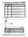
Alarm Request
This service allows PLC to ask to PROFINET stack the alarm received from a specific IO-Device.
This service has to be used in relation with the IOD_MGT_ALARM and IOD_ALARM_IND Alarm
registers see 3.1.6.
Request Format
Word
Offset
0
ID
RequestID
Value
PLC value
1
2
ServiceID
0x06
3
Status
0x55
4
DeviceID
Requested
Device
5
6
API
0x00
7
8
SlotNumber
0x00
9
SubslotNumber
0x00
10
Index
0x00
11
Data length (byte)
0x00
12
PnDeviceID
0x00
13
PnVendorID
0x00
14-21
ARUUID
0x00
(c) 2011 MITSUBISHI ELECTRIC CORPORATION
PROFINET Controller ME1PN1FW-Q
22-29
Reserved
Reserved (0x00)
Response Positive Format (Status = 0)
Word
Offset
ID
Value
RequestID
Same as the request
2
ServiceID
0x06
3
Status
0x00
4
DeviceID
Requested Device
6
Data length
(byte)
Data size
7
ErrorDecode
0x00
8
ErrorCode1
0x00
9
ErrorCode2
0x00
10-19
reserved
0x00
20
API
API number used to perform
the alarm
22
Priority
Alarm priority
23
Type
Alarm type
24
Slot number
Slot number of the alarm
25
SubSlot number
Subslot number of the alarm
26
Specifier
Alarm specifier
27
Module ident
number
Module ID of the Alarm
SubModule ident
number
submodule ID of the Alarm
31
Data length
Data Size in byte
Data
Data
0 to 1432 bytes
0
1
Header
5
21
Data
28
29
30
(c) 2011 MITSUBISHI ELECTRIC CORPORATION
36
37
GX Configurator-PN
Alarm priority:
High priority : 0x06
Low priority: 0x05
Alarm Type:
Value
(hexadecimal)
Meaning
0x0000
Reserved
0x0001
Diagnosis
0x0002
Process
0x0003
Pull
0x0004
Plug
0x0005
Status
0x0006
Update
0x0007
Media Redundancy
0x0008
Controlled by supervisor. Logical “Pull” of a
submodule to withdraw ownership
0x0009
Released. Logical “Plug” of a submodule to
return ownership or trigger a reparameterization
0x000A
Plug Wrong Submodule
0x000B
Return of Submodule
0x000C
Diagnosis disappears
0x000D
Multicast communication mismatch notification
0x000E
Port data change notification
0x000F
Sync data changed notification
0x0010
Isochronous mode problem notification
0x0011
Network component problem notification
0x0012
Time data changed notification
0x0013
Dynamic Frame Packing problem notification
0x0014
MRPD problem notification
0x0015
System Redundancy
0x0016 – 0x001D
Reserved
0x001E
Upload and retrieval notification
0x001F
Pull module
0x0020 – 0x007F
Manufacturer specific
(c) 2011 MITSUBISHI ELECTRIC CORPORATION
PROFINET Controller ME1PN1FW-Q
Value
(hexadecimal)
Meaning
0x0080 – 0x00FF
Reserved for profiles
0x0100 – 0xFFFF
Reserved
Alarm specifier: coding of bit fields is shown below:
bits
Description
Value
0-10
Sequence
number
0 to 2,047, incremented upon
each indication
11
Diagnostis
channel
0x00: No diagnosis available
Specific
diagnosis
0x00: No diagnosis available
Diagnostis
sub-module
0x00: No diagnosis available
14
Reserved
0x00
15
AR diagnostis
0x00: No diagnosis available
12
13
0x01: Diagnosis available
0x01: Diagnosis available
0x01: Diagnosis available
0x01: Diagnosis available
Response Negative Format
Word
Offset
ID
Value
Request ID
Same as the request
2
ServiceID
0x06
3
Status
!= 0x00
4
Device ID
0x00
6
Data length
(byte)
0x00
7
ErrorDecode
!= 0x00
8
ErrorCode1
!= 0x00
0
1
Header
5
(c) 2011 MITSUBISHI ELECTRIC CORPORATION
38
39
GX Configurator-PN
9
ErrorCode2
!= 0x00
10-19
reserved
0x00
Possible values for Status
Value
Comment
0
Status OK
1
Profinet stack not started
7
Device not configured
8
Profinet error see others status
9
No Alarm for this device
Alarm Ack
This service sends to the IO-Device the Ack alarm frame. This service has to be used in relation with
the IOD_MGT_ALARM and IOD_ALARM_IND Alarm registers.
Request Format
Word
Offset
ID
Value
RequestID
PLC value
2
ServiceID
0x07
3
Status
0x55
4
DeviceID
Requested device
API
API number used to perform
the ACK
8
SlotNumber
Slot number targeted
9
SubslotNumber
Subslot number targeted
10
Index
has to be contain the alarm
priority .
11
Data length (byte)
0x00
12
PnDeviceID
0x00
0
1
5
6
7
(c) 2011 MITSUBISHI ELECTRIC CORPORATION
PROFINET Controller ME1PN1FW-Q
13
PnVendorID
0x00
14-21
ARUUID
0x00
22-29
Reserved
Reserved (0x00)
Response positive format (Status = 0)
Word
Offset
ID
Value
Request ID
Same as the request
2
ServiceID
0x07
3
Status
0x00
4
Device ID
Requested device
6
Data length
(byte)
0x00
7
ErrorDecode
0x00
8
ErrorCode1
0x00
9
ErrorCode2
0x00
10-19
reserved
0x00
ID
Value
RequestID
Same as the request
2
ServiceID
0x07
3
Status
!= 0x00
4
DeviceID
0x00
Data length
(byte)
0x00
0
1
Header
5
Response negative format
Word
Offset
0
1
Header
5
6
(c) 2011 MITSUBISHI ELECTRIC CORPORATION
40
41
GX Configurator-PN
7
ErrorDecode
!= 0x00
8
ErrorCode1
!= 0x00
9
ErrorCode2
!= 0x00
10-19
reserved
0x00
Possible values for Status
Value
Comment
0
Status OK
1
Profinet stack not started
7
Device not configured
8
Profinet error see others status
9
No alarm for this device
IO-Device Information
Request format
Word
Offset
ID
0
Value
PLC value
RequestID
1
2
ServiceID
0x08
3
Status
0x55
4
DeviceID
Requested device
5
6
0x00
API
7
8
SlotNumber
0x00
9
Subslot Number
0x00
10
Index
0x00
11
Data length (byte)
0x00
12
PnDeviceID
0x00
(c) 2011 MITSUBISHI ELECTRIC CORPORATION
PROFINET Controller ME1PN1FW-Q
13
PnVendorID
0x00
14-21
ARUUID
0x00
22-29
Reserved
Reserved (0x00)
Response positive format (Status = 0)
Word
Offset
ID
Value
Request ID
Same as the request
2
ServiceID
0x08
3
Status
0x00
4
Device ID
Requested Device
6
Data length
(byte)
0x24
7
ErrorDecode
0x00
8
ErrorCode1
0x00
9
ErrorCode2
0x00
10-19
reserved
0x00
0
1
Header
5
20
Mac address
21
22
23
IP address
24
Data
25
Input @ area in High Speed
Area
26
27
output @ area in High Speed
Area
28
29
Input length
30
Output Length
(c) 2011 MITSUBISHI ELECTRIC CORPORATION
42
43
GX Configurator-PN
31
Refresh period
32
Number of successul
connections
33
Number of disconnections
34
State (Connected/Not
Connected)
35
Management (Manual
Automatic)
36
Current Profinet Status
37
Response negative format
Word
Offset
ID
Value
Request ID
Same as the request
2
ServiceID
8
3
Status
!= 0
4
Device ID
0
6
Data length
(byte)
0
7
ErrorDecode
!= 0
8
ErrorCode1
!= 0
9
ErrorCode2
!= 0
10-19
reserved
0
0
1
Header
5
Possible values for Status
Value
Comment
0
Status OK, function
1
Profinet stack not started
10
Bad Device ID (Device not configured)
(c) 2011 MITSUBISHI ELECTRIC CORPORATION
PROFINET Controller ME1PN1FW-Q
Alarm Log
This request allow to get an alarm description from the internal alarm log
- Function has to be called several times to get several alarm description
- The older alarm is returned first
Request format
Word
Offset
ID
Value
RequestID
PLC value
2
ServiceID
0x09
3
Status
0x55
4
DeviceID
Requested device
API
0
8
SlotNumber
0
9
SubslotNumber
0
10
Index
0
11
Data length (byte)
0
12
PnDeviceID
0
13
PnVendorID
0
14-21
ARUUID
0
22-29
Reserved
Reserved (0)
0
1
5
6
7
Response positive format (Status = 0)
Word
Offset
ID
Value
RequestID
Same as the request
ServiceID
0x09
0
Header
1
2
(c) 2011 MITSUBISHI ELECTRIC CORPORATION
44
45
GX Configurator-PN
3
Status
0x00
4
DeviceID
Requested Device
6
Data length (byte)
0
7
ErrorDecode
0x00
8
ErrorCode1
0x00
9
ErrorCode2
0x00
10-19
reserved
0x00
20
Date
Date of the PROFINET
Controller when the frame has
been received
Time
Time of the PROFINET
Controller when the frame has
been received
5
21
22
23
24
Alarm Type
25
API
API number used to perform
the alarm
26
Data
27
Alarm Priority
28
ModuleID
ID of the module. Manufacturer
dependant.
SubModuleID
ID of the module. Manufacturer
dependant.
32
Slot
Slot number of the alarm
33
SubSlot
Subslot number of the alarm
34
Alarm specifier
29
30
31
Response negative format
Word
Offset
ID
Value
RequestID
Same as the request
0
Header
1
(c) 2011 MITSUBISHI ELECTRIC CORPORATION
PROFINET Controller ME1PN1FW-Q
2
ServiceID
0x09
3
Status
!= 0x00
4
DeviceID
0x00
6
Data length
(byte)
0x00
7
ErrorDecode
!= 0x00
8
ErrorCode1
!= 0x00
9
ErrorCode2
!= 0x00
10-19
reserved
0x00
46
5
Possible values for Status
Value
Comment
0
Status OK, function
1
PROFINET stack not started
2
No ethernet link
7
Device not configured
8
PROFINET error see others status
9
No alarm in log
Alarm Management
A IO-device is able to send alarms to the IO-controller. When a alarm is received, the IO-controller is
expected to get the alarm description, then to acknowledge the alarm.
An IO-device can send up to 2 alarms simultaneously:
- one alarm of High Priority
- one alarm of low priority.
The IO-device won’t be able to initiate a new alarm of the respective priority as long as the IOcontroller has not “acknowledge” the previous one
By default, the PROFINET stack can handle alarm automatically without reporting any indication to
the PLC program. However, PLC can decide to manage or not by itself alarms for each device. This
can be done using the IOD_MGT_ALARM registers. With these eight 16bit registers the PLC can
indicate, how the firmware should for each IO-device manage alarms.
From CPU to PROFINET IO-Controller
Global Variable Identifier
IO-Device
Number
(c) 2011 MITSUBISHI ELECTRIC CORPORATION
Values
47
GX Configurator-PN
vPN_MGMT_OUTPUTS.IOD_MGT_ALARM[0]
…
0
..
0
1
Automatic
Manual
..
15
..
Automatic
vPN_MGMT_OUTPUTS.IOD_MGT_ALARM[16]
16
Automatic
…
..
vPN_MGMT_OUTPUTS.IOD_MGT_ALARM[31]
31
..
Automatic
…
…
….
….
vPN_MGMT_OUTPUTS.IOD_MGT_ALARM[116]
116
Automatic
…
..
vPN_MGMT_OUTPUTS.IOD_MGT_ALARM[127]
127
..
Automatic
Manual
..
vPN_MGMT_OUTPUTS.IOD_MGT_ALARM[15]
Manual
Manual
..
Manual
Manual
For an IO-device in automatic mode the IO-controller automatically acknowledges each alarm
received from an IO-device (IOD_ALARM_IND bits are not used). For an IO-device in manual mode
an alarm indication is signalled to the PLC program via the IOD_ALARM_IND registers.
From IO-Controller to CPU
Register
Function
vPN_MGMT_INPUTS.IOD_ALARM_IND[0]
Alarm has been received from the device 0
…
Alarm has been received from the device n
vPN_MGMT_INPUTS.IOD_ALARM_IND[127]
Alarm has been received from the device 127
Note: the stack can store internally both high and low priority alarms. When the CPU requests
alarms, the high priority alarm will be returned first. The IOD_ALARM_IND bit for the corresponding
device will be reset only after the management of both alarms.
The following diagram demonstrates an alarm cycle (when alarm management is activated by the
PLC program).
(c) 2011 MITSUBISHI ELECTRIC CORPORATION
PROFINET Controller ME1PN1FW-Q
48
Note: a ring buffer exists for each device. This ring buffer stores up to seven alarms for each IOdevice. Each incoming alarm is logged in this ring log buffer, from which the PLC can read using
acyclic requests.
2.1.4
Network Diagnostics
PROFINET IO Controller Status
The bits in these two words provide information on the IO-controller stack state.
From PROFINET IO-Controller to CPU
Values
Global Variable Identifier
vPN_MGMT_INPUTS.IOC_STS_CON
FIG_OK
0
1
No configuration.
Configuration OK.
vPN_MGMT_INPUTS.IOC_STS_CON
FIG_DOWNLOADING
A new configuration is
downloading
vPN_MGMT_INPUTS.IOC_STS_KEY
FILE_ERROR
Missing or wrong keyfile
vPN_MGMT_INPUTS.IOC_STS_STA
RTED
Not Started
Started
vPN_MGMT_INPUTS.IOC_STS_ERR
OR_DIAG_SET
No error
Error occured (see
Diagnostic area)
vPN_MGMT_INPUTS.IOC_STS_PLC
_WD_ERR
Watchdog ok or watchdog
mechanism disabled
Watchdog mechanism
detects that PLC is not
(c) 2011 MITSUBISHI ELECTRIC CORPORATION
49
GX Configurator-PN
running.
Possible combinations of the flags IOC_STS_CONFIG_OK, IOC_STS_CONFIG_DOWNLOADING,
IOC_STS_KEYFILE_ERROR and IOC_STS_STARTED with their respective meaning are
Flags Set
Comment
no flag set
There is no configuration inside the PROFINET Controller.
To use PROFINET download a configuration
IOC_STS_KEYFILE_ERROR
BAD pnengine.dat.
IOC_STS_CONFIG_DOWNLOADIN
G
A new configuration download is pending.
IOC_STS_CONFIG_OK
Configuration is valid. Waiting start from PLC
IOC_STS_CONFIG_OK and
IOC_STS_STARTED
Configuration is valid. PROFINET is started.
* During a configuration download sequence .IOC_STS_CONFIG_OK is off (= "No Configuration").
At the end of the configuration download sequence, the new configuration will be immediately
started, if the IOC_START_STOP.bit0 equals 1.
If IOC_STS[1].bit2 is set, the MAC address protection mechanism detected an issue and
PROFINET cannot be started.
(c) 2011 MITSUBISHI ELECTRIC CORPORATION
PROFINET Controller ME1PN1FW-Q
50
IOD_CONN_STS Registers
The following 128 bits contain the connection state of each IO-device.
PROFINET IO-Controller to CPU
IO-Device
Global Variable Identifier
vPN_MGMT_INPUTS.IOD_CONN_STS[0]
…
vPN_MGMT_INPUTS.IOD_CONN_STS[15]
Number
Values
0
1
Not
Connected
Connected
0
..
15
vPN_MGMT_INPUTS.IOD_CONN_STS[16]
16
…
..
vPN_MGMT_INPUTS.IOD_CONN_STS[31]
31
…
…
vPN_MGMT_INPUTS.IOD_CONN_STS[116]
116
…
..
vPN_MGMT_INPUTS.IOD_CONN_STS[127]
127
IOD_ERR_STS Registers
The following 128 bits indicate for each IO-device, whether an error has occurred.
PROFINET IO-Controller to CPU
IO-Device
Global Variable Identifier
vPN_MGMT_INPUTS.IOD_ERR_STS[0]
…
vPN_MGMT_INPUTS.IOD_ERR_STS[15]
number
0
1
No Error
Error
0
..
15
vPN_MGMT_INPUTS.IOD_ERR_STS[16]
16
…
..
vPN_MGMT_INPUTS.IOD_ERR_STS[31]
31
…
…
vPN_MGMT_INPUTS.IOD_ERR_STS[116]
116
…
..
vPN_MGMT_INPUTS.IOD_ERR_STS[127]
127
For each IO-device the following combinations are possible:
(c) 2011 MITSUBISHI ELECTRIC CORPORATION
Values
51
GX Configurator-PN
IOD_CONN_STS
IOD_ERR_STS
Meaning
0
0
IO-device not connected because no connection
requested.
1
0
IO-device connected, connection without error.
0
1
IO-device not connected.
In automatic mode connection not possible.
In manual, last connection request failed.
1
1
IO-device connected but connection in error
Device Advanced Status (IOD_ADV_STS Registers)
For each IO-device a byte in the variable 'vPN_ACYCLIC_DIAG_INPUTS.IOD_ADV_STS' contains
the detailed status error code, when the corresponding bit in IOD_ERR_STS is set. Each element in
the word array 'IOD_ADV_STS' contains the status codes of two devices, the status of the device
with an odd index is placed in the low byte, the status of the device with an even index is placed in
the high byte.
IOD_CONN_STS,
IOD_ERR_STS
Byte Value in
IOD_ADV_STS
Comment
N/A
0
IO-device Status is not set. (no error)
1,1
1
The IO-device produces in stop mode
1,1
2
One of IOPS in input frame is in bad.
1,1
3
One of IOCS in input frame is in bad.
1,1
4
IO-device Configuration does not match.
1,1
5..99
Reserved
0,1
100
No answer from the IO-device at the DCP identify
request. The configured name is not present on
the network.
0,1
101
Duplicate name for the IO-device. The DCP identify
request received several answers from different IOdevices.
0,1
102
Duplicate IP address detected during DCP identify
request.
0,1
103
Out of AR resource. The device is already
connected and do not accept more connection.
0,1
103-252
Reserved, to be completed during development.
0,1
253
Connection failed.
0,0
254
Never connected. This IO-device ID is present in
(c) 2011 MITSUBISHI ELECTRIC CORPORATION
PROFINET Controller ME1PN1FW-Q
52
the configuration, but the PROFINET stack never
sent a connect request.
0,0
255
Not used. This IO-device ID is not present in the
configuration.
Diagnostic Area (ADV_DIAG_* Registers)
In the ADV_DIAG_* registers the PROFINET stack can report some advanced information on the
PROFINET Controller state (used for technical support only).
From IO-Controller to CPU
Global Variable Identifier
Contents
0: Stack running well
1: MAC address check fails
vPN_ACYCLIC_DIAG_INPUTS.ADV_DI
AG_ERR_CODE
PROFINET stack
error code
2: MAC file encrypted not found
3: Assert
4: Error system
vPN_ACYCLIC_DIAG_INPUTS.ADV_DI
AG_ERR_CODE2
PROFINET stack
error code (high
word)
vPN_ACYCLIC_DIAG_INPUTS.ADV_DI
AG_ADD_INFO
Additional information depending on the main error
code. See below
Error
code
value
Additional information (word 2 to 19)
0
All 0
0
1
2
1
2
MAC address
PROFINET
Controller
3
4
0 (currently not used)
5 6
7
.
.
..
..
.
.
..
.
.
17
18
5 6
7
.
.
..
..
.
.
..
.
.
17
18
MAC
address
stack
All 0
0
1
2 3
4
3
Line in
the file
File name where the assert appears.
(c) 2011 MITSUBISHI ELECTRIC CORPORATION
53
GX Configurator-PN
4
2.1.5
0
1
2
3
ErrCde
ErrDec
Errcod1
Errcod2
…
18
PLC Program Watchdog
LIVE_WORD_X and LIVE_WORD_Y Registers
The live word register variables 'vPN_CYCLIC_INPUTS.LIVE_WORD_X' and
'vPN_CYCLIC_OUTPUTS.LIVE_WORD_Y' allows the PLC to activate a watchdog mechanism
between the PLC program and the PROFINET Controller. By default this mechanism is not activated
(LIVE_WORD_X =0)
The following scenario applies:
By default the LIVE_WORD_Y register is set to 0, meaning that no check is activated.
To activate the mechanism, PLC sets LIVE_WORD_Y to 1 or to any value different from 0
The IO-controller reads the LIVE_WORD_Y value in an interval of 500 ms. If the value is identical
three consecutive times (1.5s) and differs from 0, the IO-controller will consider the PLC as no longer
running. In this case IO-controller sets the IOC_STS.bit17 for indication.
If activated this watchdog mechanism is the only way for the IO-controller to detect that a PLC
program is currently running. In this case any attempt to download a new configuration will display a
warning message to alert the end user.
Once the mechanism is activated the PLC has to write a new value each 500 ms. The mechanism
can be stopped at any time by writing 0 again to the LIVE_WORD_Y register.
Each 500ms the IO-controller also copies the LIVE_WORD_Y read value in the LIVE_WORD_X
register If the PLC does not read the same value after a maximum of 1 second, the PLC can
consider that the IO-controller is no longer running and start any appropriate action.
(c) 2011 MITSUBISHI ELECTRIC CORPORATION
PROFINET Controller ME1PN1FW-Q
2.1.6
54
PLC and PROFINET Controller States (RUN/STOP)
PLC
STATE
PROFINET
Controller
STATE
Comment
RUN
RUN
PROFINET stack is in RUN.
IOPS and IOCS have status GOOD
Input data are updated in the High Speed Area
RUN
STOP
PROFINET stack is in STOP.
Output data = old values and IOPS and IOCS set to BAD
Input data are updated in the high speed area
STOP
RUN
PROFINET stack is in RUN.
Output data = old values an IOPS and IOCS set to GOOD
Input data are updated in the high speed area
STOP
STOP
PROFINET stack is in STOP.
Output data = old values an IOPS and IOCS set to BAD
Input data are updated in the high speed area
2.2
LED Display
2.2.1
User LED
The 'USER' LED is the bottom-right one in the six LEDs group on the front of the ME1PN1FW-Q.
This LED signals PROFINET Controller specific states in combination with the 7-segment LED
display. For the meaning of the other LEDs please consult the user manual of the Q12DCCPU-V.
State
Meaning
RED
Error, see 7 segments LED
RED slow blink
Some IO-devices are not connected.
RED rapid Blink
Network storm
(c) 2011 MITSUBISHI ELECTRIC CORPORATION
55
2.2.2
GX Configurator-PN
Green
All OK. All IO-devices connected whatever their mode (manual or
automatic)
Green slow blink
All OK. All IO-devices in automatic mode are connected. All IO
devices in manual mode are not connected.
Green rapid Blink
All OK. All IO-devices in automatic mode are connected. Some IO
devices in manual mode are connected, some are not connected
Orange
All IO-devices connected whatever their mode (manual or automatic).
However, some configuration mismatches exist.
Orange slow blink
All IO-devices in automatic mode are connected. All IO devices in
manual mode are not connected. However, some configuration
mismatches exist.
Orange rapid
Blink
All IO-devices in automatic mode are connected. Some IO devices in
manual mode are connected, some are not connected. However, some
configuration mismatches exist.
7-Segment LED Display
The 7-segment display is located on the front of the ME1PN1FW-Q.
It indicates PROFINET Controller specific states in combination with the status of the User LED.
User
LED
Red fix
7 segment
value
Meaning
1
No Ethernet link
2
No configuration
3
No IO-device connected
4
The engine.dat file is corrupted.
5
Stack failed to start
6
Declare Device failed (config corrupt)
7
Error system see 3.1.7.4.
(c) 2011 MITSUBISHI ELECTRIC CORPORATION
PROFINET Controller ME1PN1FW-Q
Green fix
Off
All IO-devices connected
N/A
BL
A DCP blink command is receiving.
OFF
8
Wait Start from register.
9
The stack can’t start. The initialization sequence failed
10
Memory allocation error during initialization sequence
11
CNFMAST.001 is missing in folder \RAM\Profinet\Default
12
CNFDEVIC.001 is missing in folder \RAM\Profinet\Default
13
CNFNAME.001 is missing in folder \RAM\Profinet\Default
14
copycross10.bin is missing in folder \RAM\Profinet\Default
15
CNFMAST.001 is missing in folder \RAM\Profinet
16
CNFDEVIC.001 is missing in folder \RAM\Profinet
17
CNFNAME.001 is missing in folder \RAM\Profinet
18
copycross10.bin is missing in folder \RAM\Profinet
19
Configuration files Access error. File is open but not readable
20
Configuration files check error. Values read in the file are not
acceptable. Configuration of high speed area is wrong
21
Init controller failed. Cannot start the PROFINET firmware
22
GX Configurator Remote access initialization failed
Red fix
(c) 2011 MITSUBISHI ELECTRIC CORPORATION
56
57
3
GX Configurator-PN
Getting to know GX Configurator-PN
GX Configurator-PN Concept
GX Configurator-PN (GXPN) is the configuration tool for PROFINET I/O interfaces in MITSUBISHI
PLCs. It provides functions for defining a PROFINET I/O network, validating the configuration and
downloading it to the respective PLC module via a MITSUBISHI automation network.
GX Configurator-PN is capable of downloading configuration data to the PROFINET I/O module via a
variety of different communication types. The module can be located in a PLC rack directly
connected to the PC or in a PLC rack, which is connected to other PLCs in a separate network.
GX Configurator-PN takes information on PROFINET I/O slaves from GSD files, which are specific to
the respective slave and usually provided by the slave hardware vendor. It generates multi-CPU
parameters for use in GX Developer (GD) and GX IEC Developer (GID).
User Interface
The graphical user interface of GX Configurator-PN assists the user by making the most important
functions easily accessible.
The main items of the user interface are
Main Menu
Toolbar
Configuration View
PROFINET Network View
Device Library View
Network Detection View
Items View
Message View
(c) 2011 MITSUBISHI ELECTRIC CORPORATION
Installation
4
58
Installation
Before You Begin
Copyright
Important Notice:
This software is protected by copyright. By opening the distribution disks package
you automatically accept terms and conditions of the license agreement.
You are only permitted to make one single copy of the original distribution disks for your
own backup and archiving purposes.
Software Purpose
This software is a configuration utility software package which will be used to configure the following
PROFINET I/O network interface modules of MELSEC System Qn series PLCs:
PROFINET I/O master module ME1PN1FW-Q
4.1
System Requirements
To install the GX Configurator-PN software package your computer has to meet the following
requirements
Minimum Hardware Requirements
Pentium II 350 Mhz processor (for Vista: 1 GHz processor)
256 MB RAM for Microsoft ® Windows XP
1 GB RAM for Microsoft ® Windows Vista
VGA compatible graphics adapter
17"/43 cm diag. VGA monitor
At least 200 MB free hard disk space
CD-ROM drive
interface for communication with the PLC system
Software Requirements
GX Configurator-PN is a 32-bit software that runs on the following operating systems
Microsoft ® Windows XP Home or Professional Edition
Microsoft ® Windows Vista Home (or higher)
Microsoft ® Windows 7 Home (or higher), both 32- and 64-bit versions
Related MELSOFT Software
GX Configurator-PN is typically used together with one of the PLC programming packages for
MITSUBISHI PLCs
'GX Developer' (GD)
'GX IEC Developer' (GID)
'GX Works 2' (GXW2)
Certain functions of GX Configurator-PN are restricted or not available for specific PLC programming
packages.
(c) 2011 MITSUBISHI ELECTRIC CORPORATION
59
4.2
GX Configurator-PN
Software Installation
GX Configurator-PN Setup
To install the GX Configurator-PN software you need to have Microsoft ® Windows properly installed.
You may require administrator privileges when installing the software.
If an older version of GX Configurator-PN is already installed, uninstall it first. After the de-installation
please start the installation of the new version. If you want to keep the older version of GX
Configurator-PN, please select a different directory for the new version. A de-installation of the older
version, after the newer version has been installed, will also damage the newer version. Therefore
please reinstall the new version after uninstalling both the older and the newer GX Configurator-PN
versions, if you encounter problems. Please stop all other running software before the installation
and do not run other installation programs during the installation of GX Configurator-PN.
Installing GX Configurator-PN
To start the installation, proceed as follows:
1. Insert the installation CD-ROM into your CD-ROM drive.
2. If you have 'Autorun' enabled for the drive, the setup should start automatically.
3. If the setup is not started automatically, please locate the 'setup.exe' file and execute it.
4. If you see the following message on a Windows ® Vista operating system, please select
'Allow'
5. Follow the given instructions that guide you through the installation procedure. Continue with
Next.
(c) 2011 MITSUBISHI ELECTRIC CORPORATION
Installation
60
6. The licensing agreement is displayed. Please read these terms carefully. If you accept the
license agreement, you can proceed with the installation by clicking Next. Otherwise the
installation is aborted.
7. Enter your name, organization and the product serial number. Click on Next to proceed.
(c) 2011 MITSUBISHI ELECTRIC CORPORATION
61
GX Configurator-PN
8. Enter the destination folder where you want the GX Configurator-DP software to be installed
(default C:\Program Files\MELSOFT\GX Configurator-PN 1.02). If you want to install to a
different directory, click on Change and select the installation directory. If you agree with the
default setting, just click on Next.
9. The installation is started by pressing the Install button.
(c) 2011 MITSUBISHI ELECTRIC CORPORATION
Installation
62
10. After pressing the 'Install' button the installation is started. Progress bars will inform you
about the setup status.
11. After the installation has been successfully completed, you see the following message
(c) 2011 MITSUBISHI ELECTRIC CORPORATION
63
GX Configurator-PN
Button Functions
With the Next button you will leave the current menu and enter the next menu.
With the Back button you go to the previous window.
Cancel button ends the installation procedure.
4.3
Installing the DCP Protocol Driver
The DCP protocol must be manually added to the Ethernet interface, which is used for
communication with the PROFINET Controller. The procedure is specific for each of the following
supported operating systems
Windows XP
Windows Vista
Windows 7
Note: you may need administrator rights for the following steps!
(c) 2011 MITSUBISHI ELECTRIC CORPORATION
Installation
4.3.1
64
Windows XP
1.) Open the Control Panel and double click "Network Connections" to open the Network Connection
Settings.
2.) Right click "Local Area Connection" and select "Properties" to open the "Local Area Connection
Properties".
(c) 2011 MITSUBISHI ELECTRIC CORPORATION
65
GX Configurator-PN
3.) Click "Install" to open the "Select Network Component Type" dialog.
(c) 2011 MITSUBISHI ELECTRIC CORPORATION
Installation
66
4.) Select "Protocol" from the List and click "Add..." to open the "Select Network Protocol" dialog.
5.) Select "MITSUBISHI ELECTRIC" from the "Manufacturer" List and after that "MITSUBISHI DCP
driver" from the "Network Protocol" List. Then click "OK" to confirm the selection.
(c) 2011 MITSUBISHI ELECTRIC CORPORATION
67
GX Configurator-PN
The "MITSUBISHI DCP driver" is now added to the Protocol List in the dialog "Local Area Connection
Properties".
4.3.2
Windows Vista
1.) Open the Control Panel and click "View network status and tasks" to open the "Network and
Sharing Center".
2.) Click "View Status" of the "Local Area Connection" to open the "Local Area Connection Status".
(c) 2011 MITSUBISHI ELECTRIC CORPORATION
Installation
3.) Click "Properties" to open the "Local Area Connection Properties".
(c) 2011 MITSUBISHI ELECTRIC CORPORATION
68
69
GX Configurator-PN
4.) Answer the "User Account Control" with "Continue" to step further to the "Local Area Connection
Properties".
5.) Click "Install..." to open the "Select Network Feature Type" dialog.
(c) 2011 MITSUBISHI ELECTRIC CORPORATION
Installation
70
6.) Select "Protocol" from the List and click "Add..." to open the "Select Network Protocol" dialog.
7.) Select "MITSUBISHI ELECTRIC" from the "Manufacturer" List and after that "MITSUBISHI DCP
driver" from the "Network Protocol" List. Then click "OK" to confirm the selection.
(c) 2011 MITSUBISHI ELECTRIC CORPORATION
71
GX Configurator-PN
The "MITSUBISHI DCP driver" is now added to the Protocol List in the dialog "Local Area Connection
Properties".
4.3.3
Windows 7
1.) Open the Control Panel and click "View network status and tasks" to open the "Network and
Sharing Center".
2.) Click "Local Area Connection" to open the "Local Area Connection Status".
(c) 2011 MITSUBISHI ELECTRIC CORPORATION
Installation
3.) Click "Properties" to open the "Local Area Connection Properties".
(c) 2011 MITSUBISHI ELECTRIC CORPORATION
72
73
GX Configurator-PN
4.) Click "Install..." to open the "Select Network Feature Type" dialog.
5.) Select "Protocol" from the List and click "Add..." to open the "Select Network Protocol" dialog.
6.) Select "MITSUBISHI ELECTRIC" from the "Manufacturer" List and after that "MITSUBISHI DCP
driver" from the "Network Protocol" List. Then click "OK" to confirm the selection.
(c) 2011 MITSUBISHI ELECTRIC CORPORATION
Installation
74
The "MITSUBISHI DCP driver" is now added to the protocol list in the dialog "Local Area Connection
Properties".
4.4
PROFINET Controller Installation
The PROFINET Controller must be in its factory default settings, before the PROFINET I/O firmware
can be installed and started. If the module has been used before or any problems are encountered
during the PROFINET I/O firmware installation, the module must first be set to its factory defaults.
For the detailed procedure see the section 'Troubleshooting - Factory Default Settings'.
To install the PROFINET I/O firmware the CF card received from MITSUBISHI must be inserted in the
CF card slot on the module.
1. reset the module to initiate copying the contents of the CF card to the ME1PN1FW-Q memory
2. wait, until the 7-segment LED shows 'AA', indicating that the script on the CF card has been
completed without an error
3. now remove the CF card and reset the controller
4. start GX Configurator-PN, create a configuration with the correct MAC address of the PROFINET
Controller and enter the IP address you want for the PROFINET Controller.
(c) 2011 MITSUBISHI ELECTRIC CORPORATION
75
GX Configurator-PN
5. download the configuration (this includes setting the IP address from the default setting of the
PROFINET Controller to the address assigned in the GX Configurator-PN project)
6. update the refresh settings on both the controlling Qn-CPU and the PROFINET Controller in the
''PLC Settings' dialog'.
(c) 2011 MITSUBISHI ELECTRIC CORPORATION
Installation
(c) 2011 MITSUBISHI ELECTRIC CORPORATION
76
77
5
GX Configurator-PN
Getting Started
Below are the main steps, which are required to configure a PROFINET I/O master module.
Start GX Configurator-PN
1. Start GX Configurator-PN via the shortcut in the Programs menu. The default location of the
shortcut is Programs \ MELSOFT Application \ GX Configurator-PN 1.02 \ GX ConfiguratorPN 1.02.
Start a New Project
1. In the main menu File select Configuration Manager.
2. in the Configuration Manager press New to create a new configuration project
(c) 2011 MITSUBISHI ELECTRIC CORPORATION
Getting Started
78
After closing the 'Configuration Manager' dialog the 'Add New ME1PN1FW-Q' dialog is displayed.
The user must select the local network interface, the ME1PN1FW-Q is connected to. The user can
then choose to obtain the network address of the module either automatically or manually. For
details see the description of the 'Add New ME1PN1FW-Q' dialog.
3. the inserted module is now displayed in the network view and slaves can be added by drag&drop
from the 'Device Library'.
(c) 2011 MITSUBISHI ELECTRIC CORPORATION
79
GX Configurator-PN
or by scanning the network for slave devices using the 'Network Detection View' .
4. the configuration of a slave can be edited by selecting 'Properties' from the context menu of the
slave
(c) 2011 MITSUBISHI ELECTRIC CORPORATION
Getting Started
80
5. after completing the network settings the configuration can be downloaded to the ME1PN1FW-Q
with the item 'Download Configuration' from the 'File' menu.
(c) 2011 MITSUBISHI ELECTRIC CORPORATION
81
6
GX Configurator-PN
Main Menu
Starting GX Configurator-PN
Select GX Configurator-PN from the Windows Start menu. The default shortcut is
Start -> Programs -> MELSOFT Applications -> GX Configurator-PN 1.02 -> GX ConfiguratorPN 1.02
Main menu
The main menu offers the following pull-down menus.
Main Menu
Items
Description
File
opening, saving and downloading configurations
Description
add/remove a PROFINET Controller
Library
managing the library with the device types
Network
functions related to scanning an existing network
Devices
adding/removing devices from/to the network
Items
configuring data items in device modules
Help
help and application information
The items in the open pull-down menus can be reached via mouse or keyboard. The underlined
character will start the function. In addition there are some menu items which may be started using
predefined shortcuts.
6.1
File Menu
After having started the GX Configurator-PN software, this is the first menu to work with. With the
help of this menu you can create a new or load an existing project.
The menu offers the following commands:
Command
Description
(c) 2011 MITSUBISHI ELECTRIC CORPORATION
Main Menu
82
Configuration Manager
Opens the project manager for selecting and managing
configuration projects
Save
Save the current configuration
List and Print
Opens the ‘Preview and Print Listings’ dialog
PLC Settings
Opens the 'PLC Settings' dialog
Download
Configuration
Download the configuration to the PROFINET controller
Download
Configuration in
Memory Card
Download the configuration to the memory card in the PROFINET
controller
Preferences
Selects the user interface layout, active ‘Advanced Mode’
Message View
Functions related to the ‘Message View’
Exit
End application
Command 'Save'
This item saves the modifications of the current configuration.
'List and Print'
Opens the 'Preview or Print Listings' Dialog.
Command 'PLC Settings'
The 'PLC Settings' dialog provides the user interface for configuring the data exchange between the
PROFINET Controller and the controlling Qn-CPU. This includes
assigning buffer devices
updating refresh settings in Qn-CPU, PROFINET Controller and/or the PLC programming project
checking existing refresh settings
For details see 'PLC Settings' dialog.
Command 'Download Configuration'
The current configuration is downloaded to the RAM of the PROFINET Controller.
Note: please make sure that the refresh settings for the interaction with the PLC program are
consistent with the configuration of the PROFINET Controller by updating the refresh settings in the
'PLC Settings' dialog after a download of the PROFINET Controller configuration.
Command 'Download Configuration in Memory Card'
The current configuration is downloaded to the CF-card inserted in the PROFINET Controller.
Command 'Preferences'
Command
Description
(c) 2011 MITSUBISHI ELECTRIC CORPORATION
83
GX Configurator-PN
Workspace
Toggles the display of the 'Configuration View', the 'Device Library View'
and the 'Network Detection View'
Output Window
Toggles the display of the 'Message View' window
Advanced Mode
Toggles 'Advanced Mode'
Command 'Message View'
This item opens the 'Message View' menu.
Command 'Exit'
You can use this menu command to quit the software. If the configuration has been modified and
has not yet been saved the following message appears
If you want to save the last changes before leaving and ending GX Configurator-PN choose Yes. If
you choose No, all modifications to the respective project are lost.
6.1.1
'Preview or Print Listings' Dialog
View and print the settings of the current configuration.
Name
Description
Choices
/ Range
Default
Devices Configuration
If selected, the I/O devices and their
configuration are included in the printout
-
-
Items Configuration
If selected, the data items are included in
the printout
-
-
Preview
Shows the contents of the selected
configuration in the default text editor
-
-
(c) 2011 MITSUBISHI ELECTRIC CORPORATION
Main Menu
6.2
Print
Prints the selected part of the
configuration on the default printer
-
-
Print All Listing
Prints devices and items on the default
printer
-
-
Help
Open online help
-
-
Cancel
Close the dialog
-
-
Description Menu
The menu contains the following commands:
Command
Description
Add ME1PN1FW-Q
Add PROFINET Controller to configuration
Delete ME1PN1FW-Q
Remove PROFINET Controller from configuration
Properties
Open 'Properties' dialog for PROFINET Controller
Command 'Add ME1PN1FW-Q'
Add a ME1PN1FW-Q to the configuration
Command 'Delete ME1PN1FW-Q'
Remove the ME1PN1FW-Q from the configuration
6.3
Help Menu
The menu contains the following commands:
Command
Description
Console Help
Opens the online help
About
Displays version information
(c) 2011 MITSUBISHI ELECTRIC CORPORATION
84
85
GX Configurator-PN
7
User Interface
7.1
Device Library
The device library is the local collection of descriptions for types of PROFINET I/O devices.
The parameters used for configuring an IO-Device are contained in a GSDML file (Generic Station
Description Markup Language), commonly called a GSD. A GSD may contain one or more IODevice descriptions.
The device library is used to store GSD files and to provide a graphic view. Using this graphic view, it
is possible to manually insert IO-Devices into the current configuration. The device library is also
accessed during automatic detection of IO-devices present on the network.
Context Menu
For the nodes in the device library tree context menus exists. The entries depend on the type of the
selected node.
This menu is also accessible via the main menu. For a detailed description see 'Libray Menu'.
Library Display Options
The selector above the device library tree allows you to choose the display mode.
The available options are
(c) 2011 MITSUBISHI ELECTRIC CORPORATION
User Interface
Display Name
Display the product name
Display Order Number
Display the order number
86
Adding IO-Device Types to the Library
The 'GSDML Management' wizard lets you add one or more IO-Devices to the library. This wizard
may be accessed via the
button or via the menu item ‘Add…’ from the context menu of the
device library or the ‘Library’ submenu in the main menu. For details see 'Add GSDML Files'.
7.1.1
Library Menu
The menu contains the following commands:
Command
Description
Add
Add device type with GSDML file to library
Delete
Remove device type from library
Device types must not be deleted while being used in the configuration.
Note: deleting a GSD from the library does not physically delete the
GSD file on the hard disk. It is instead moved to the subdirectory
'removed_gsdml'
Sort
Sort the entries in the library
Insert in Configuration
Add selected device type to library
Properties
Show properties of the selected device type
Sort Device Library
Select the criteria for sorting the entries in the device library
(c) 2011 MITSUBISHI ELECTRIC CORPORATION
87
GX Configurator-PN
Name
Description
Choose the type of sort Select the criteria for sorting the
entries in the device library
Available sort keys are:
Choices /
Range
Default
Category /
Category
Manufacturer /
File name /
By Category: Displays IO-Devices
according to their main type then
their secondary type. This sort is
based on the "Main Family" and
"Product Family" fields in the GSD
for the IO-Device.
IO-Device
name
By Manufacturer: Displays the IODevice by manufacturer. This sort is
based on the "VendorName" field in
the GSD for the IO-Device.
By File name: Displays the IODevices according to the GSD
filename.
By IO-Device name: Displays the
IO-Devices by name. This sort is
based on the "Name" field in the
GSD for the IO-Device.
OK
Close dialog and save changes
Cancel
Close dialog and discard changes
(c) 2011 MITSUBISHI ELECTRIC CORPORATION
User Interface
7.1.2
88
'GSDML Management' Dialog
This wizard-style dialog is opened to add device types defined in GSDML files to the device library.
(c) 2011 MITSUBISHI ELECTRIC CORPORATION
89
GX Configurator-PN
Name
Description
Choices /
Range
Default
Add File(s)
Add one or more GSDML files
Selected / not
selected
Selected
Selected / not
selected
Not
selected
Use the [Browse] button to select
the files.
If the file already exists, the 'File
Already Exists' warning is
displayed.
Add all the GSDML
from the Directory
Add the GSDML files in a specified
directory and (optionally) its
subdirectories
Use the [Browse] button to select
the files.
If a file already exists, the 'File
Already Exists' warning is
displayed.
Look in Subfolders
If selected, also the subfolders of
the selected directory are searched
for GSDML files.
Selected / not
selected
Not
selected
Directory or File Name
Path of the selected file(s) or
directory
-
-
Browse
Open a file dialog for selecting the
GSDML file(s) or the directory to
search
-
-
Back
Go back to the start page
-
-
Next
Proceed and add the selected file
or scan the selected directory
-
Default
button
Cancel
Close wizard and discard changes
-
-
Help
Open online help
-
-
'File Already Exists' Warning
If a file is to be added, which already exists in the library, a warning is displayed. The existing type
is not overwritten. If it should be replaced, the existing entry must be deleted first.
(c) 2011 MITSUBISHI ELECTRIC CORPORATION
User Interface
90
'Add GSD File Completed' Page
After adding one or several GSD files to the library, the next page shows for each selected GSD file,
whether it has been added to the library or not.
Name
Description
Choices /
Range
Default
Column 'File Name'
Name of GSDML file
-
-
Column 'Status'
Status (added or failure)
-
-
Columns 'Family
Name', 'Schema
Additional information taken from
the GSDML file
-
-
(c) 2011 MITSUBISHI ELECTRIC CORPORATION
91
GX Configurator-PN
Name
Description
Choices /
Range
Default
View Selected File
Open the selected GSDML file in
the default text editor
-
-
Back
Go back to the previous page
-
-
Next
Proceed to the next page to end the
wizard
-
Default
button
Cancel
Close wizard and discard changes
-
-
Help
Open online help
-
-
Version',
'Manufacturer', 'File
Date' and 'File Time'
(c) 2011 MITSUBISHI ELECTRIC CORPORATION
User Interface
7.1.3
'Device Type Properties' Dialog
Name
Description
Choices / Range
Default
Tree
Structured display of the
GSD file contents
-
-
Check GSDML
Checks, whether GSD file
contents comply to the
specification (i.e. schema
definition)
-
-
View or Print GSDML
File
Displays the GSD file
contents in the default text
editor, from they can be
saved or printed
-
-
Previous
Show properties of previous
device
Disabled, if the device
is the first in the list
-
(c) 2011 MITSUBISHI ELECTRIC CORPORATION
92
93
7.2
GX Configurator-PN
Name
Description
Choices / Range
Default
Next
Show properties of next
device
Disabled, if the device
is the last in the list
-
OK
Close dialog and save
changes
-
-
Cancel
Close dialog and discard
changes
-
-
Help
Open online help
-
-
Network Detection
Instead of manually adding device types to the network configuration the user can scan the network
of the PROFINET Controller for connected devices and one or several of these devices to the current
network configuration.
The context menu of the 'Network' node corresponds to the 'Network Menu' in the main menu.
Network Tree
(c) 2011 MITSUBISHI ELECTRIC CORPORATION
User Interface
Network components with icons like this:
configuration.
94
are IO-Controllers They cannot be used in the current
Network detection will carry out an implicit read request to the IO-Device to find out the configuration
of the IO-Device's slots and sub-slots. Certain IO-Devices do not support this request and must
therefore be configured manually.
The message window contains all the IO-Devices, whose name or current IP address are not
compatible with network detection from GX Configurator-PN.
IO-Devices with an IP address, which is not of the same class as that of the IO-Controller, are
represented like this:
They cannot be inserted into the current configuration.
For PROFINET network detection to be as effective as possible, the following rules must be obeyed:
Each IO-Device must have a unique name
PROFINET uses DCP protocol to address the IO-Devices. This protocol allows a name to be
given to each IO-Device. As for the IP address, the name must be unique over the network. To
name an IO-Device, it is recommended to use the 'Online Action Tool'.
Each IO-Device must have one IP address in the same network range as the IO-Controller.
When an IO-Device is detected, an implicit read request is carried out to find out the slot/subslot configuration of the IO-Device. This request uses RPC protocol based on TCP/IP. If the IODevice is not in the same network range as the IO-Controller, then this request will fail. To
configure an IP address for an IO-Device, it is recommended to use the 'Online Action Tool'.
Each IO-Device must have its GSD present in the device library.
The configuration of an IO-Device is based on its GSD. Without a GSD file an IO-Device cannot
be configured.
(c) 2011 MITSUBISHI ELECTRIC CORPORATION
95
7.2.1
GX Configurator-PN
'Network' Menu
The menu contains the following commands:
Command
Description
Read Network Configuration
Scans the network for connected devices
Online Action
Starts the ‘Online Action’ tool for finding and identifying devices
and for setting device name and/or IP address
Insert in Configuration
Adds the selected device to the current network configuration
Insert and Replace All
Removes the devices currently configured and adds all devices
found
Properties
Opens the view with the properties of the selected device
Command 'Read Network Configuration'
This command scans the network for connected devices.
Alternatively the button
Detection] area.
can be pressed. The devices found are listed in the [Network
Command 'Online Action'
Starts the ‘Online Action’ tool for finding and identifying devices and for setting device name and/or
IP address.
Command 'Insert in Configuration'
Adds the selected device to the current network configuration.
Command 'Insert and Replace All'
Removes the devices currently configured and adds all devices found.
Command 'Properties'
Opens the view with the properties of the selected device.
(c) 2011 MITSUBISHI ELECTRIC CORPORATION
User Interface
7.2.2
96
Online Action Tool
The ‘Online Action’ tool is started via either the menu item ‘Online Action’ or by pressing the
button. When the tool is started, it issues requests to detect PROFINET stations on the network.
Name
Description
Choices
/ Range
Default
Number of Nodes on
the Network
Number of network nodes found
-
-
Network Nodes
Table
Shows the PROFINET stations present as well
as their name, IP address, type, MAC address
and addressing mode
-
-
Scanning
If checked, the network nodes list is refreshed
every 3 seconds. Otherwise the list is not
refreshed again.
-
-
MAC Address
Ethernet address of the selected device
-
-
(c) 2011 MITSUBISHI ELECTRIC CORPORATION
97
GX Configurator-PN
Name
Description
Choices
/ Range
Default
Device Type
Type of the selected device
-
-
Factory Reset
Sends a DCP request to the IO-Device telling it
to restart with its factory default settings. The
result of this command will be displayed in the
Request status field
-
-
Name
Name of the selected device
-
-
Permanent Name
Checked: the IO-Device is to store its new
name in non-volatile memory. After the next
power cycle the device must use its new
name.
-
-
-
-
-
-
Unchecked: the IO-Device is to store its new
name in volatile memory. After the next power
cycle the device goes back to its old name.
Apply Name
Sends a DCP request to the IO-Device telling it
to use its new name.
The result of this command will be displayed in
the Request status field.
For further information see 'Naming an IODevice'.
Addressing Mode
There are three available addressing modes:
DCP: the IO-Controller may change the TCP/IP
configuration of the device. The IO-Controller
will change the TCP/IP configuration of the IODevice if it differs from the TCP/IP configuration
of the IO-Device contained in the IO-Controller
configuration.
DHCP: In this mode, the IO-Device obtains its
TCP/IP configuration from a DHCP server. The
criterion for obtaining the TCP/IP configuration
from the DHCP server is configurable in the
‘DHCP Based on’ list.
Note: if an IO-Device is configured in DHCP
mode and a connection is established, the IOController compares the TCP/IP configuration
of the IO-Device with that contained in the
configuration of the IO-Controller. If they differ,
the connection cannot be established.
(c) 2011 MITSUBISHI ELECTRIC CORPORATION
User Interface
98
Name
Description
Choices
/ Range
Default
DHCP Based on
MAC address: the identifier used for obtaining
the IP configuration from the DHCP server will
be the MAC address of the IO-Device.
-
-
Station name: the identifier used for obtaining
the IP configuration from the DHCP server will
be the name of the IO-Device.
Client identifier: the identifier used for
obtaining the IP address from the DHCP server
will be the character string entered by the user
in the [Client Identifier] field.
Local: This parameter cannot be selected. It is
there for information only if the IO-Device is
already set to local mode.
Client Identifier
The identifier used for obtaining the IP address
from the DHCP server
-
-
IP Address
IP address to be set in the device
-
-
Sub-Network Mask
Sub-network mask to be set in the device
-
-
Gateway IP Address
Gateway IP address to be set in the device
-
-
Permanent
Checked: the IO-Device is to store its new IP
configuration in non-volatile memory. When it is
next turned on, it must use its new IP
configuration.
-
-
-
-
Unchecked: the IO-Device is to store its new IP
configuration in volatile memory. When it is
next turned on, it must use its new IP
configuration.
Apply
Sends a DCP request to the IO-Device for it to
use its new TCP/IP configuration.
The result of this command will be displayed in
the Request status field.
For further information see 'Configure the IP
Address of an IO-Device'
Blinking Test
If the GSDML file of the selected device exists
in the device library and contains the
‘DCP_FlashOnceSignalUnit’ tag, the text from
the GSDML file indicates the device behaviour
when it receives a DCP flash command.
-
-
Device Blinking
The ‘Blinking Device’ dialog is displayed and
DCP blink commands are sent to the device.
-
-
(c) 2011 MITSUBISHI ELECTRIC CORPORATION
99
GX Configurator-PN
Name
Description
Choices
/ Range
Default
Help
Open online help
-
-
Close
Close dialog
-
Default
button
Request Status
Lists the results of the commands issued in
this dialog
-
-
Naming an IO-Device
When an IO-Device is selected from the list, the name of the selected IO-Device is shown in the
Name field and the Write to device button is enabled.
This command sends a DCP request to the IO-Device telling it to use its new name.
The Permanent name checkbox is used as follows:
Checked: the IO-Device is to store its new name in non-volatile memory. When it is next turned
on, it must use its new name.
Unchecked: the IO-Device is to store its new name in volatile memory. When it is next turned on,
it goes back to its old name.
The result of this command will be displayed in the Request status field.
Naming rules for an IO-Device
The name of an IO-Device is made up of 1 to 240 characters and must comply with the following
rules:
1 or more labels separated by [.]
the size of a label varies from 1 to 63 characters
total size (sum of all label and [.] character) varies from 1 to 240 characters
the allowed characters are [a-z0-9], upper-case letters are prohibited
labels may not start with [-]
labels may not terminate with [-]
labels may not start with [port-xyz] or [port-xyz-abcde] where a,b,c,d,e,x,y,z = 0..9
Configure the IP Address of an IO-Device
(c) 2011 MITSUBISHI ELECTRIC CORPORATION
User Interface
100
When an IO-Device is selected from the list, the TCP/IP configuration of the selected IO-Device is
shown in the addressing field and the [Apply] button is enabled.
.
There are three available addressing modes:
DCP: In this mode, although the IO-Device has a TCP/IP configuration, when an IO-Controller
connects to this IO-Device, the IO-Controller may change the TCP/IP configuration of this IODevice. The IO-Controller will change the TCP/IP configuration of the IO-Device if it differs from the
TCP/IP configuration of the IO-Device contained in the IO-Controller configuration.
DHCP: In this mode, the IO-Device obtains its TCP/IP configuration from a DHCP server. The
criterion for obtaining the TCP/IP configuration from the DHCP server is configurable. The DHCP
based on gives the following options:
MAC address: the identifier used for obtaining the IP configuration from the DHCP server will be
the MAC address of the IO-Device.
Station name: the identifier used for obtaining the IP configuration from the DHCP server will be
the name of the IO-Device.
Client identifier: the identifier used for obtaining the IP address from the DHCP server will be the
string entered in the client identifier field.
If an IO-Device is configured in DHCP mode: when a connection is established, the IO-Controller
compares the TCP/IP configuration of the IO-Device with that contained in the configuration of
(c) 2011 MITSUBISHI ELECTRIC CORPORATION
101
GX Configurator-PN
the IO-Controller. If they differ, the connection cannot be established.
Local: This parameter cannot be selected. It is there for information only if the IO-Device is
already set to local mode.
7.3
PROFINET Network View
The PROFINET network view is the central view of the application. It lists
PROFINET controller
assigned I/O devices
modules of the I/O devices
Operations for the network view are contained in the 'Devices' Menu.
Diagnostic Mode
The diagnostic mode is activated with the menu item 'Start Console Diagnostic' or by pressing the
button.
After configuring the IO-Controller, adding and configuring the devices of your network and
downloading your configuration to the board, the statuses of all devices can be tested with the
internal diagnostic tool. This tool gives a first level diagnosis of the status of the current
configuration. When the diagnostic mode is enabled, the configuration cannot be changed. It is in
read-only mode.
Once enabled, the diagnostic view shows the current status of the connection for each IO-Device.
Indicates that the IO-Device is connected
(c) 2011 MITSUBISHI ELECTRIC CORPORATION
User Interface
102
Indicates that the IO-Device is disconnected but that a connection phase is under way
Indicates that the IO-Device is not connected. Connection is controlled by the user
'Device Name Properties' Dialog
The device name can be changed from its default, which is the type name taken from the GSD file.
7.3.1
'Devices' Menu
The menu contains the following commands:
Command
Description
Duplicate
Add a copy of the selected device
Delete
Remove the selected device
Delete all
Remove all devices
Disable all
Disable all devices
Enable all
Enable all devices
Duplicate X times
Add multiple copies of the selected device
Properties
If the PROFINET Controller is selected:
opens the 'PROFINET Controller Properties' dialog
If an IO device is selected:
opens the ‘PROFINET I/O Device Properties’ dialog
Start Console Diagnostic
Start diagnostic mode
Stop Console Diagnostic
Stop diagnostic mode
(c) 2011 MITSUBISHI ELECTRIC CORPORATION
103
GX Configurator-PN
Command
Description
Options
Opens the ‘Display Option’ dialog
Properties
The effect of this menu item depends on the node, which is selected in the network tree.
7.3.2
Node Type
Properties Dialog
Channel
'Channel Properties' Dialog
PROFINET Controller
'ME1PN1FW-Q Properties' Dialog
IO-Device
'IO-Device Configuration' Dialog
Item Configuration - Device
PROFINET Network View - 'Device Name Properties' Dialog
Item Configuration - Slot
'Items Declaration' Dialog
Module Configuration
'IO-Device Configuration' Dialog - Tab 'Module Configuration'
Module Name
'Module Configuration' Dialog
'Display Option' Dialog
The display of the PROFINET network tree can be modified with the options in this dialog.
Name
Display device IP
Description
Choices /
Range
If enabled, displays the IP address of the device Active /
Default
Inactive
(c) 2011 MITSUBISHI ELECTRIC CORPORATION
User Interface
Name
7.3.3
Description
Choices /
Range
104
Default
address in the tree
in the current configuration tree.
Inactive
Display device
number in the tree
If enabled, displays the number of the device in
the current configuration tree.
Active /
Inactive
Active
Add GSDML in
library: Message for
redundant GSDML
If enabled, displays a message if a GSDML file Active /
for the same device with the same file version is Inactive
already in the GSDML database. This GSDML
file will not be inserted into the device library.
Active
Parameter
Description
Shows a descriptive text to the selected
parameter
Read-only
-
OK
Close dialog and save changes
-
Default
button
Cancel
Close dialog and discard changes
-
-
Help
Open online help
-
-
'Channel Properties' Dialog
This dialog provides access to timing parameters for the PROFINET I/O communication. The
displayed values depend on whether 'Advanced Mode' has been selected or not.
In 'Standard Mode':
(c) 2011 MITSUBISHI ELECTRIC CORPORATION
105
GX Configurator-PN
DCP section
Request time-out
Sets the maximum time from the IO-Controller sending a DCP
request from the reply. It also sets the listening time of the IOController to the DCP identification request
Number of request retries
Sets the maximum number of times a DCP request is repeated
following a timeout.
RTA (Real Time with Acknowledgment) section
Request time-out
Sets the maximum period separating the time from the IOController sending a RTA request and the reply.
Number of request retries
Sets the maximum number of times an RTA request is
repeated following a timeout.
In 'Advanced Mode':
RPC section - Client
Maximum number of pings
Sets the maximum number of pings while awaiting a response.
Maximum number of re-sends
Sets the maximum number of times an RPC frame is repeated
(question or response).
Timeout on CANCEL request
Sets the maximum time from the IO-Controller sending an RPC
cancel request to the reply.
(c) 2011 MITSUBISHI ELECTRIC CORPORATION
User Interface
106
Timeout on Fragment
Acknowledge
Sets the maximum time separating the IO-Controller sending
an RPC ACK request from the reply.
Timeout on sending first ping
Sets the maximum time separating the IO-Controller sending
the first RPC PING request from the reply.
Timeout on resending first ping
Sets the maximum time separating the IO-Controller sending
an RPC PING request from the response to the first PING.
RPC section - Server
7.3.4
Maximum number of re-sends
Maximum times a telegram is retransmitted before signalling
an error.
Timeout before resending
Interval to wait before retransmitting a telegram.
IP Address Manager
This dialog provides access to the network address settings of the PROFINET Controller and to the
'IP Address Manager'.
PROFINET Controller Network Address Settings
(c) 2011 MITSUBISHI ELECTRIC CORPORATION
107
GX Configurator-PN
Name
Description
Choices
/ Range
Default
Table
IP Address: area of 4 bytes entered in decimal
notation with decimal point representing the
Internet address or IP address of the PROFINET
Controller channel 1 (CH1)
-
-
Sub-Network Mask: defines the addresses to be
routed by the gateway and the network of valid IP
addresses.
Gateway IP Address: IP address of a machine
which can perform routing to another network.
PROFINET is not an IP-based protocol. It will not
be possible to route I/O exchanges through a
gateway.
Controller Name: PROFINET name of the IOController.
Description
Provides help on the selected field.
read-only
-
OK
Close dialog and save changes
-
Default
button
Cancel
Close dialog and discard changes
-
-
Help
Open online help
-
-
IP Address Manager
The ‘IP Address Manager’ service manages the IP address allocation for IO-Devices present in the
configuration.
(c) 2011 MITSUBISHI ELECTRIC CORPORATION
User Interface
108
Name
Description
Choices /
Range
Default
Address
Ranges
define one or more IP address ranges
-
-
-
-
IP addresses from these ranges will be
distributed by the console when an IO-Device is
added.
The address ranges are managed using the
following buttons:
Creates an address range
Edits the selected address range
Deletes the selected address range
Address
Assignments
To reserve IP addresses for predefined IODevice names
(c) 2011 MITSUBISHI ELECTRIC CORPORATION
109
GX Configurator-PN
Name
Description
Choices /
Range
Default
-
-
not
selected
This is useful for IO-Devices with addresses
which must remain fixed. When the respective
IO-Device is inserted into the current
configuration, the corresponding IP address will
automatically be assigned to it.
Scan
Get a list of I/O devices on the network
The
button is used to copy device name
and IP address to the ‘Configured Assignments’
list. Alternatively the
button allows to make
an assignment by specifying the IP address and
the name of the IO-Device.
Enable this
Service
Enable the ‘IP Address Manager’ service
selected /
not selected
Sub-Network
Mask
Sub-netwok mask from the configuration of the
PROFINET Controller
read-only
The subnetwork mask along with the gateway
address cannot be configured using this
service.
Gateway IP
Address
Gateway address from the configuration of the
PROFINET Controller
read-only
Configured
Assignments
List of configured pairs of device name and IP
address, which are assigned by the address
manager, when the device is connected.
-
-
: Edits the selected entry
: Deletes the selected entry
OK
Close dialog and save changes
-
Default
button
Cancel
Close dialog and discard changes
-
-
Help
Open online help
-
-
When a connection is established, the PROFINET Controller can send the TCP/IP configuration to
an IO-Device. This helps to avoid problems with IP address conflicts. The IP addresses distributed
by the console will only be effective, when the PROFINET Controller establishes the connection with
the IO-Device.
(c) 2011 MITSUBISHI ELECTRIC CORPORATION
User Interface
7.4
Items View
Lists the I/O points of the module selected in the network configuration view.
The context menu in the view corresponds to the 'Items Menu' in the main menu.
7.4.1
'Items' Menu
The menu contains the following commands:
Command
Description
Add Item(s)
Add item(s)
Delete Item(s)
Delete selected item(s)
Rename Item
Rename the selected item
Properties
Properties of the selected item
Command 'Add Item(s)'
Opens the 'Items Declaration' dialog to define new items or edit existing ones.
Command 'Delete Item(s)'
The selected item(s) are deleted, when the following query is confirmed.
(c) 2011 MITSUBISHI ELECTRIC CORPORATION
110
111
GX Configurator-PN
Command 'Rename Item'
Opens an edit field in the cell with the name of the selected item
Command 'Properties'
This command opens the 'Item Properties' dialog.
7.4.2
'Items Properties' Dialog
Name
Description
Choices /
Range
Default
Item Name
Item name
1 - 50 characters
-
Data Type
Item data type
read-only
-
Block Offset in Device
Offset of the item within the input
or output area of the device in
bytes
read-only
-
Item Offset in the
Block
Offset of the item within its block in
bytes
read-only
-
Previous
Show settings of previous item in
table
Enabled, the
selected item is
not the first one
-
Next
Show settings of next item in table
Enabled, the
-
(c) 2011 MITSUBISHI ELECTRIC CORPORATION
User Interface
Name
Description
Choices /
Range
112
Default
selected item is
not the last one
7.4.3
Help
Open online help
-
-
OK
Close dialog and save changes
-
Default
button
Cancel
Close dialog and discard changes
-
-
'Items Declaration' Dialog
Opens the 'Items Declaration' dialog for defining items.
Name
Description
Choices / Range
Default
Numeric Input Items
Table with items in input area
read-only
-
Numeric Output Items
Table with items in output area
read-only
-
(c) 2011 MITSUBISHI ELECTRIC CORPORATION
113
GX Configurator-PN
Name
Description
Choices / Range
Default
Default Items Name
Root
Prefix for item names
SLOT<nnn>
with <nnn>
being the slot
in the slave
Input DUT Name
Name of the struct, which
contains the items
-
Define Item(s)
opens the 'Define Item(s)' dialog
Enabled, if an
unallocated area is
selected; disabled, if
an existing item is
selected
-
Delete Item(s)
delete selected item(s)
Enabled, if an
existing item is
selected
-
Define Bit(s)
opens the 'Define Bit(s)' dialog
Enabled, if an
existing item is
selected
-
OK
Close dialog and save changes
-
Default
Cancel
Close dialog and discard
changes
-
-
Help
Open online help
-
-
Warning: when changing the data type of an item the memory position may change. Elements of
WORD, DWORD and REAL types are always placed on a word boundary. This may require insertion
of padding bytes and thus change the sizes of the transfer buffers for the cyclic data. Therefore the
refresh settings must always be updated in both the PLC CPU and the PROFINET Controller.
Define Item(s)
Define one or more items.
(c) 2011 MITSUBISHI ELECTRIC CORPORATION
User Interface
114
Name
Description
Choices /
Range
Default
Data Type
Data type of the item
Byte, Word,
Dword, IEEE float
Byte
Define Selected Area
Select, whether either several
single items or an item of array
type is created
Single Items /
Array
Single Items
Item Name
Name of the new item
1 - 50 characters
-
OK
Close dialog and save changes
-
Default
button
Cancel
Close dialog and discard changes
-
-
Help
Open online help
-
-
Define Bit(s)
Define items for individual bits in the selected item of type 'Byte' or larger.
(c) 2011 MITSUBISHI ELECTRIC CORPORATION
115
GX Configurator-PN
Name
Description
Choices /
Range
Default
Discrete Input Items
Table with items in input area
read-only
-
Default Items Name
Root
Prefix for item names
-
SLOT<nnn>
with <nnn>
being the slot
within the
slave
Define Item(s)
opens the 'Item Name Definition'
dialog
Enabled, if a very
unallocated area
is selected;
disabled, if an
existing item is
selected
-
or
Discrete Output Items
(see 'Bit Item Definition')
Delete Item(s)
delete selected item(s)
Enabled, if an
existing item is
selected
-
OK
Close dialog and save changes
-
Default
button
Cancel
Close dialog and discard changes
-
-
Help
Open online help
-
-
Bit Item Definition
Specify the name(s) for one or multiple bit items
Name
Description
Choices /
Range
Default
Define Selected Area
Select, whether either several
single items or an item of array
Single Items /
Array
Single Items
(c) 2011 MITSUBISHI ELECTRIC CORPORATION
User Interface
Name
Description
Choices /
Range
Default
type is created
7.5
Item Name
Name of the new item
1 - 50 characters
-
OK
Close dialog and save changes
-
Default
button
Cancel
Close dialog and discard changes
-
-
Help
Open online help
-
-
Message View
The message view shows the entries of the events log.
The message view contains a context menu.
7.5.1
'Message View' Menu
Command
Description
Copy
Copies the contents of the message view to the clipboard
Clear
Deletes the contents of the message view
Configuration
Opens the 'Output Message View Configuration' dialog
(c) 2011 MITSUBISHI ELECTRIC CORPORATION
116
117
7.5.2
GX Configurator-PN
'Message View Configuration' Dialog
This dialog is used to configure the message view.
Name
Description
Choices /
Range
Default
Maximum Log File
Size
Maximum size of log file
1 - 2000000 kB
1024 kB
Add Date to
Messages
Add date field to entries
selected / not
selected
selected
Add Level to
Messages
Add level field to entries
selected / not
selected
selected
OK
Close the dialog and save changes
-
Default
Cancel
Close the dialog and discard
changes
-
-
(c) 2011 MITSUBISHI ELECTRIC CORPORATION
User Interface
7.6
118
Configuration Manager
Each project with the settings for a PROFINET Controller is a ‘configuration’ and stored in a fixed
directory. The ‘Configuraton Manager’ provides the UI for managing several PROFINET I/O projects.
Name
Description
Choices / Range
Default
Active Configuration
Name of currently open
controller project
read-only
-
Configuration Path
Directory of active
configuration
read-only
-
Available
Configurations
Names of existing
configurations
read-only
-
Created
Date, when configuration has
been created
read-only
-
Modified
Date, when configuration has
been modified for the last
time
read-only
-
Description
Descriptive text of
configuration
read-only
-
Create a new configuration
-
New
(c) 2011 MITSUBISHI ELECTRIC CORPORATION
(to change press
'Rename')
(to change press
'Properties')
-
119
GX Configurator-PN
Name
Description
Choices / Range
Default
Enabled, if a
configuration is selected;
otherwise disabled
-
Opens the 'New
Configuration' dialog
Duplicate
Create a copy of the
selected configuration
Opens the 'Duplicate
Configuration' dialog
Rename
Opens the 'Rename
Configuration' dialog for the
selected configuration
Enabled, if a
configuration is selected;
otherwise disabled
-
Delete
Delete the selected
configuration
Enabled, if a
configuration is selected
and it is not the only one;
otherwise disabled
-
Properties
Opens the ‘Configuration
Properties’ dialog for the
selected configuration
Enabled, if a
configuration is selected;
otherwise disabled
-
Restore
Opens a file dialog for
selecting a *.mit file created
as backup before, which is
added to the list of
configurations
-
-
Backup
Opens a file dialog for
selecting a *.mit file, the
selected configuration is
exported to
-
-
OK
Close dialog and save
changes
-
-
Close
Close dialog and discard
changes
-
-
Help
Open online help
-
-
(c) 2011 MITSUBISHI ELECTRIC CORPORATION
User Interface
7.6.1
120
'New Configuration' Dialog
The user enters the name and a descriptive text for the new configuration.
7.6.2
Name
Description
Choices /
Range
Default
Configuration
Name of the selected configuration
1-124
characters
-
Description
Descriptive text of configuration
-
-
Created
Date, when configuration has been
created
read-only
-
Modified
Date, when configuration has been
modified for the last time
read-only
-
Configuration Path
Directory of configuration
read-only
-
OK
Close dialog and save changes
-
Default
Cancel
Close dialog and discard changes
-
-
'Duplicate Configuration' Dialog
Enter the name of the new 'copied' configuration.
(c) 2011 MITSUBISHI ELECTRIC CORPORATION
121
7.6.3
GX Configurator-PN
Name
Description
Choices /
Range
Default
Source Configuration
Name
Name of the selected original
configuration
read-only
-
New Configuration
Name
New name for the copy of the selected
configuration
1-124
characters
-
OK
Close dialog and save changes
-
Default
Cancel
Close dialog and discard changes
-
-
'Rename Configuration' Dialog
Enter a new name for the selected configuration.
Name
Description
Choices
/ Range
Default
Old Configuration
Name
Current name of the selected configuration
read-only
-
New Configuration
Name
New name for the selected configuration
1-124
characters
-
OK
Close dialog and save changes
-
-
Cancel
Close dialog and discard changes
-
Default
(c) 2011 MITSUBISHI ELECTRIC CORPORATION
User Interface
7.6.4
122
'Configuration Properties' Dialog
Edit the configuration description.
Name
Description
Choices /
Range
Default
Configuration
Name of the selected configuration
read-only
-
Description
Descriptive text of configuration
Created
Date, when configuration has been
created
read-only
-
Modified
Date, when configuration has been
modified for the last time
read-only
-
Configuration Path
Directory of configuration
read-only
-
Open Folder
Opens the Windows file explorer and
selects the configuration directory
-
-
OK
Close dialog and save changes
-
Default
Cancel
Close dialog and discard changes
-
-
(c) 2011 MITSUBISHI ELECTRIC CORPORATION
-
123
7.7
GX Configurator-PN
'ME1PN1FW-Q Properties' Dialog
Address settings of a ME1PN1FW-Q can be manually entered or copied from station found during a
network scan.
Name
Description
Choices / Range
Default
Board Name
List of local Ethernet interfaces
to select the one, the
PROFINET Controller is
connected to
local Ethernet
interfaces
-
MAC Address
MAC address of selected
Ethernet interface
6 pairs of hex digits
separated by colons
-
Status
Connection status of selected
Ethernet interface
read-only
-
IP address
IP address(es) assigned to
selected Ethernet interface
read-only
-
Detect
Scan the network of the
selected network adapter for
suitable network stations. The
controllers found are added to
the list.
-
-
Blink
Flashes the LED display on the
PROFINET Controller
Enabled, if a module
entry in the table is
selected
-
(c) 2011 MITSUBISHI ELECTRIC CORPORATION
User Interface
Name
7.8
Description
Choices / Range
Default
124
>>
Copies the address of the
selected PROFINET Controller
to the ‘Configured...' section
Enabled, if a module
entry in the table is
selected
-
ME1PN1FW-Q
Controller model name
read-only
ME1PN1FW
-Q
IP Address
Controller IP address
Name
Controller name
MAC Address
MAC address of selected
controller
Blink
Flashes the LED display on the
PROFINET Controller
-
-
Connection Test
Tries to connect to the
PROFINET Controller
-
-
OK
Close dialog and save changes
-
Default
button
Cancel
Close dialog and discard
changes
-
-
Help
Open online help
-
-
4 integers in the range
of 0-254
0.0.0.0
6 pairs of hex digits
separated by colons
-
'IO-Device Configuration' Dialog
This dialog is displayed, when a new device is added to the network view, and when the item
‘Properties’ is selected from the context menu of the device in the network view. The settings of a
PROFINET I/O slave device are accessed via the following tab pages in this dialog
'Device - General Configuration' Tab
'Device - Module Configuration' Tab
'Device - Parameters' Tab
'Device - Connection Information' Tab
'Device - I/O Data' Tab
'Device - GSDML File' Tab
(c) 2011 MITSUBISHI ELECTRIC CORPORATION
125
7.8.1
GX Configurator-PN
'Device - General Configuration' Tab
Lists general parameters like name and IP address of the corresponding I/O device.
Name
Description
Choices /
Range
Name
Name of the IO-device
Number
Device ID to be chosen from the list of devices
not configured.
Default
Model
name
0 - 127
Link Parameters Checkbox to activate the link of the device
number with the device IP address: the device
number will then correspond to the station
number of the IP address.
Active
Configuration
Checkbox to activate the configuration of the
device in the IO-Controller: used to delete a
device from IO-Controller, whilst keeping its
configuration in the console.
(c) 2011 MITSUBISHI ELECTRIC CORPORATION
User Interface
Name
Description
Comments
Free text related to a device. The total number of
characters must not exceed 80.
Addressing
Mode
Defines the way of obtaining the IP configuration
which may be DCP, Local or DHCP. The modes
vary according to the contents of the GSD for
the IO-Device.
Choices /
Range
126
Default
0 - 80
characters
DCP: during the connection, the IO-Controller
sets the IP address of the IO-Device.
DHCP: during the connection, the IO-Controller
compares the IP address of the IO-Device with
that configured. If they are identical, the
connection can go ahead. If not, the connection
fails.
Local: during the connection, the IO-Controller
uses the configured IP address.
IP Address
This IP address will be the IP address of the IODevice after connection if the selected
addressing is DCP.
This IP address shall be the same as the IP
address configured inside the IO-Device if the
selected addressing mode is different than DCP.
Device Name
This field shall be the same as name configured
inside the IO-Device. (See Name an IO-Device)
Description
Provides help on the selected field.
read-only
Previous
Get settings of previous I/O device (slave)
disabled for first device
Next
Get settings of next I/O device (slave)
disabled for last device
OK
Close dialog and save changes
-
Cancel
Close dialog and discard changes
-
-
Help
Open online help
-
-
-
Default
button
Note: when creating a configuration from the ‘Network Detection View’ (aka ‘automatic configuration
mode’), IP address and name of the device are already set. When manually adding the device, these
items must be entered by the user.
(c) 2011 MITSUBISHI ELECTRIC CORPORATION
127
7.8.2
GX Configurator-PN
'Device - Module Configuration' Tab
This tab is used to select the modules in the IO-Device.
Name
Description
Choices /
Range
Default
Available
Modules
Contains the list of modules compatible
with the IO-Device configured. This list
was established from the device library.
From this list, it is possible to add the
modules present on the IO-Device to the
list of configured modules.
-
-
When a module can be configured,
double-clicking the slot opens an editor for
the module settings. The settings
displayed are taken from the GSD file.
Therefore the settings differ from between
modules.
(c) 2011 MITSUBISHI ELECTRIC CORPORATION
User Interface
128
Name
Description
Choices /
Range
Default
Display Order
Number
If selected, only the order number from the
GSDML file is displayed, otherwise the
module type name
selected / not
selected
not selected
Configured
Modules
Modules in the I/O device per slot with
their type names
-
-
-
-
: Opens the ‘Module Configuration’
dialog.
: Moves the selected module up in the
list
: Moves the selected module down in
the list
: Deletes the selected module; same
as pressing the [Del] key.
Adds a module from the list of modules
available to the list of those configured.
Other ways of carrying out this
command:
Double click the module to be added
Drag and drop the module to be added
Previous
Get settings of previous I/O device (slave)
disabled for
first device
-
Next
Get settings of next I/O device (slave)
disabled for
last device
-
OK
Close dialog and save changes
-
Default
button
Cancel
Close dialog and discard changes
-
-
Help
Open online help
-
-
Note: when creating a configuration from the ‘Network Detection View’ (aka ‘automatic configuration
mode’), the module list is already filled. When manually adding the device, the modules must be
added by the user.
(c) 2011 MITSUBISHI ELECTRIC CORPORATION
129
7.8.3
GX Configurator-PN
'Device - Parameters' Tab
Device specific parameters can be edited.
Name
Description
Choices /
Range
Default
Refresh Period
Time interval in milliseconds between the
transmission of each production frame and the
reception of each consumption frame.
-
16 ms
Device Data
Order
Data order for the device
‘Little
Endian’ /
‘Big
Endian’
‘Big
Endian’
Used to specify the data format in memory of
the 16 and 32-bit words:
"Little Endian (Intel)" format: In increasing
address order: low order byte – high order byte.
"Big Endian (Motorola)" format: In increasing
address order: high order byte - low order byte
(c) 2011 MITSUBISHI ELECTRIC CORPORATION
User Interface
130
Name
Description
Choices /
Range
Default
Watchdog
Factor
This value is used to calculate the production
and consumption time out period.
-
3
Time out period = Refresh period * Watchdog
factor
The result is displayed in the Watchdog field.
Watchdog
Production and consumption timeout period
read-only
-
Description
Provides help on the selected field.
read-only
-
Previous
Get settings of previous I/O device (slave)
disabled for
first device
-
Next
Get settings of next I/O device (slave)
disabled for
last device
-
OK
Close dialog and save changes
-
Default
button
Cancel
Close dialog and discard changes
-
-
Help
Open online help
-
-
(c) 2011 MITSUBISHI ELECTRIC CORPORATION
131
7.8.4
GX Configurator-PN
'Device - Connection Information' Tab
Show online status information for the respective IO-device.
Name
Description
Choices /
Range
Default
Connection State Indicates, whether the IO-Controller is
connected to or disconnected from the IODevice.
-
-
PROFINET
Status
The values of the stati displayed are those
defined by the PROFINET standard.
-
-
List of Invalid
Modules in
Configuration
The IO-Controller may connect to an IO-Device
with an imprecise module configuration. In this
case, the IO-Device may accept the connection
while indicating the differences between the
configured modules and the modules making up
the IO-Device.
-
-
Configured identification Number:
corresponds to the module configured in the
(c) 2011 MITSUBISHI ELECTRIC CORPORATION
User Interface
Name
Description
Choices /
Range
Default
engineering tool
Actual identification Number: the value for the
module present in the IO-Device
Module status: current status of the module in
the IO-Device
Production Time
Shows the configured and the current cycle time
for the device as well as the maximum and
minimum cycle time since starting the cyclic
data exchange
-
-
Search Modules
in GSDML
Lookup module information in the GSDML files
-
-
Previous
Get settings of previous I/O device (slave)
disabled for
first device
-
Next
Get settings of next I/O device (slave)
disabled for
last device
-
OK
Close dialog and save changes
-
Default
button
Cancel
Close dialog and discard changes
-
-
-
-
Help
Open online help
(c) 2011 MITSUBISHI ELECTRIC CORPORATION
132
133
7.8.5
GX Configurator-PN
'Device - I/O Data' Tab
Access the cyclic input and output data of the IO-device.
Name
Description
Choices /
Range
Status
Indicates whether the connection has been
established (OK) or not. A detailed status is
given in the information on the connection tab.
Output
Displays the output values for the IO-Device.
The output values may be changed by clicking
them.
Input
Displays the input values for the IO-Device.
Default
read-only
The input and output views include either:
Data : the background of the cell is yellow
IOPS (IO provider status) and IOCS (IO
(c) 2011 MITSUBISHI ELECTRIC CORPORATION
User Interface
Name
Description
Choices /
Range
Default
For inputs
read-only
-
consumer status): the background of the cell is
green if the value is GOOD, if not the
background of the cell is red
Set Values
Writes the modified output values to the device
Dismiss
modifications
Returns to the initial values
Data
Description
The field gives the slot number, sub-slot
number and the type of data item selected
simply by clicking a value. A data item may
be:
IOCS: Represents a consumption status
IOPS: Represents a production status
Data: Represents data.
Data Output
Status
Shows the status of the outputs production
frame called the production APDU Status..
Data Input
Status
Shows the status of the inputs production
frame called the production APDU Status.
Run / Stop
Where the IO-Controller is in stop mode, the
IO-Devices must not consume the data
received and vice-versa.
Data Valid /
Data Invalid
If the IO-Controller is in Invalid data mode, the
IO-Device must close the connection.
-
Normal
Operation /
Problem
If the IO-Controller is in Problem mode, the IODevice must close the connection.
-
Previous
Get settings of previous I/O device (slave)
disabled for
first device
-
Next
Get settings of next I/O device (slave)
disabled for
last device
-
OK
Close dialog and save changes
-
Default
button
Cancel
Close dialog and discard changes
-
-
Help
Open online help
-
-
(c) 2011 MITSUBISHI ELECTRIC CORPORATION
134
135
7.8.6
GX Configurator-PN
'Device - GSDML File' Tab
This dialog displays information from the GSD file of the device.
Name
Tree
View or Print
GSDML File…
Description
Choices /
Range
Default
Lists the entries of the GSDML file
-
-
Displays the file in a Windows text editor. This
text editor can be used to print the file. What is
displayed is a copy of the GSD with the .txt
extension.
-
-
Previous
Get settings of previous I/O device (slave)
disabled for
first device
-
Next
Get settings of next I/O device (slave)
disabled for
last device
-
OK
Close dialog and save changes
-
Default
(c) 2011 MITSUBISHI ELECTRIC CORPORATION
User Interface
Name
Description
Choices /
Range
Default
button
7.9
Cancel
Close dialog and discard changes
-
-
Help
Open online help
-
-
'Module Configuration' Dialog
The 'Module Configuration' dialog provides access to module-specific parameters.
It contains the 'Module Parameters' tab and the 'Module Information' tab.
7.9.1
'Module Parameters' Tab
Lists the parameters of the selected module as defined in the GSD file of the device type. The
settings in this tab will be sent to the IO-Device during the connection phase.
(c) 2011 MITSUBISHI ELECTRIC CORPORATION
136
137
GX Configurator-PN
Name
Description
Choices /
Range
Default
Name
Parameter name
read-only
-
Value
Parameter value
device
specific
device
specific
Description
Descriptive text for parameter
read-only
-
Previous
Go to the previous module of the device
disabled for
the first
module
-
Next
Go to the next module of the device
disabled for
the last
module
-
OK
Close dialog and save changes
-
Default
button
Cancel
Close dialog and discard changes
-
-
Help
Open online help
-
-
(c) 2011 MITSUBISHI ELECTRIC CORPORATION
User Interface
7.9.2
138
'Module Information' Tab
Show information on the selected module taken from the GSD file of the IO-device.
Name
Description
Choices /
Range
Default
Information
Lists properties of the module
read-only
-
Comment
User comment for the module
Previous
Go to the previous module of the device
disabled for
the first
module
-
Next
Go to the next module of the device
disabled for
the last
module
-
OK
Close dialog and save changes
-
Default
button
(c) 2011 MITSUBISHI ELECTRIC CORPORATION
-
139
GX Configurator-PN
Name
Description
Choices /
Range
Default
Cancel
Close dialog and discard changes
-
-
Help
Open online help
-
-
Note: the values contained in this tab come from analyzing the GSD for the IO-Device. Depending on
the version of the GSD and IO-Device, the values will differ. They are displayed for information only.
7.10
'PLC Settings' Dialog
The 'PLC Settings' dialog provides the user interface for configuring the data exchange between the
PROFINET Controller and the controlling Qn-CPU.
Name
Description
Choices /
Range
Default
CPU Connection
Settings
Opens the transfer setup editor for the
configuration of the connection to the Qseries PLC
-
-
Test Connections
Tries to connect to the Q-series CPU and
to the Profinet Controller (via FTP) and
shows the results
-
-
Start I/O No. Q-CPU
Starting I/O number of the Q-CPU, which
controls the PN controller (corresponds to
sequential index of Q-CPU)
fixed 0x3E0
0x3E0
(c) 2011 MITSUBISHI ELECTRIC CORPORATION
User Interface
140
Name
Description
Choices /
Range
Default
Start I/O No.
PROFINET
Controller
Starting I/O number of the PROFINET
Controller (corresponds to sequential
index of CCPU)
fixed 0x3E1
0x3E1
PLC Programming
Project
Contains the path of the corresponding
PLC project file for either GD (gppw.gpj) or
GID (softctrl.pro)
-
empty
Browse
Opens a file dialog for selecting the GD or
GID project
-
-
Outputs
Lists the output buffers (QCPU ->
PROFINET Controller); only the device
addresses in the ‘Start’ column are
editable, other columns are readonly
for input in
the ‘Start’
column see
'Supported
PLC Device
Types' below
Inputs
Lists the input buffers (QCPU <PROFINET Controller); only the device
addresses in the ‘Start’ column are
editable, other columns are readonly
Update Parameters
Opens the 'Update Parameters' Dialog and
executes the listed updates
-
-
Diagnosis/Verify
Opens the 'Multiple CPU Refresh Settings'
dialog
-
-
IO Documentation
Generates an HTML document with global
variables and buffer devices
-
-
Export PLC Code
Opens a file dialog, where the user enters
the name of the .asc-file, in which the
program definitions and references to user
libraries are stored. For details see
section 'PLC Code for PROFINET
Controller'.
-
-
OK
Close dialog and save changes
-
Default
button
Cancel
Close dialog and discard changes
-
-
Supported PLC Device Types
The following table lists the supported device types and their respective address ranges.
Device Type
Address Range
X
0x0 – 0x1FFF
Y
0x0 – 0x1FFF
L
0 – 32767
(c) 2011 MITSUBISHI ELECTRIC CORPORATION
-
141
GX Configurator-PN
Device Type
Address Range
M
0 – 32767
D
0 – 25983
R
0 – 32767
B
0x0 – 0x7FFF
W
0x0 – 0x657F
ZR
0 – 4184063
Default Device Addresses
For a new project GX Configurator-PN assigns default device addresses to the refresh buffers
according to the following schema
Buffer
Default Device Address
PROFINET Management (Outputs)
Y0
PROFINET Management (Inputs)
X0
Acyclic Buffer (Outputs)
D0
Acyclic Buffer (Inputs)
D2100
Cyclic Output
D4542
Cyclic Input
D4542 + <cyclic output size>
The default device address of the cyclic input area is the first D-device behind the area occupied by
the cyclic outputs. It depends therefore on the cyclic output size of the network configuration.
Note: the default device address is only assigned in a new project and is not adjusted, when the
cylic output size changes due to changes in the network configuration.
Check of Overlapping Device Areas
The device addresses of the six input and output buffers are checked for overlapping devices each
time the dialog is opened. The conflicting device addresses are automatically adjusted. The following
message box is displayed:
They are also checked for overlapping devices each time the dialog is closed by pressing ‘OK’ or
when calling the ‘IO Documentation’ or ‘Export PLC Code’ functions. If device areas overlap, a
warning is displayed.
(c) 2011 MITSUBISHI ELECTRIC CORPORATION
User Interface
142
If the user presses 'OK' the conflicting device addresses are adjusted automatically. If the user
presses ‘Cancel’ the dialog remains open in order to correct the device addresses manually. The
conflicting device addresses are highlighted with red color to easily allow identification. If the
corrected device address is not overlapping any more the highlighting is canceled.
Validation of IO Identifiers
Both functions 'IO Documentation' and 'Export PLC Code' validate the identifiers used in the IO
configuration. These identifiers include the names of DUT elements listed in the 'Items' tables as well
as the global variable names of the instances of these DUTs. The identifiers must conform to
specification IEC 61131. Some of the restrictions checked are:
- global variable names must be unique within the PLC project
- identifiers must not exceed 32 characters in length
- identifiers must not contain 'hyphen' characters
- identifiers must not contain multiple consecutive underscores and must not end with one
If any of these restrictions are violated, GX Configurator-PN attempts to modify the identifiers in
question and displays warnings on the problems encountered in a separate dialog.
(c) 2011 MITSUBISHI ELECTRIC CORPORATION
143
GX Configurator-PN
Name
Description
Choices /
Range
Default
List
Messages on violations to IEC 61131
restrictions
-
-
Do not show
warnings again
If checked, this dialog is no longer displayed,
when warnings are encountered, but the
respective function (documentation or POU
export) is directly executed.
selected / not
selected
not
selected
Note: this option is de-selected, when the
program is restarted.
OK
Close dialog and proceed
-
Default
button
Cancel
Close dialog and do not display IO
documentation or export PLC code
-
-
Save
Store the displayed messages in a text file
-
-
IO Documentation
An HTML document with the global variables and corresponding buffer devices is generated and
displayed in the default web browser. The document can be saved or printed for documentation
purposes.
(c) 2011 MITSUBISHI ELECTRIC CORPORATION
User Interface
144
7.10.1 'Update Parameters' Dialog
This dialog lists, which refresh settings are updated.
Name
Description
Update Q-CPU
online
If selected, the refresh settings in the
parameter file on the CPU are updated
Update PROFINET
Controller online
If selected, the refresh settings in the
parameter file on the PROFINET Controller
are updated via FTP
Choices /
Range
Default
read-only
selected
read-only &
selected /
unselected
selected
read-only &
selected /
unselected /
selected
, if
project
path set
If the FTP connection has not been
enabled, this item is not selected
Update PLC
Project
If selected, the parameter file in the
assigned GD/GID project is updated
If no GD/GID project has been assigned,
this item is unselected.
OK
Close dialog and save changes
-
Default
button
Cancel
Close dialog and discard changes
-
-
For the data transfer between Qn-CPU and PROFINET Controller both must contain matching
refresh settings. Therefore in general both Qn-CPU and PROFINET Controller should be updated
simultaneously.
(c) 2011 MITSUBISHI ELECTRIC CORPORATION
145
GX Configurator-PN
7.10.2 'Multiple CPU Refresh Settings' Dialog
The refresh settings on the controlling Qn-CPU and on the PROFINET Controller can also be
modified via the PLC programming software. In order to control the actually existing settings, this
dialog lists the settings on all CPUs or in the selected parameter file.
Name
Description
Choices /
Range
Default
Load Parameters
reads the refresh settings from the
parameter files on the Q-CPU and the
PROFINET Controller
-
-
Load File
After selecting a GD/GID parameter file in
a file dialog, the contents of the parameter
file are displayed
-
-
Close
Close dialog
-
-
Refresh Settings on
CPU
Lists those CPUs, from which the
parameter file with the refresh settings,
could be read
0x3E0,
0x3E1,
0x3E2,
0x3E3
0x3E0
If the CPU
has settings
Refresh Settings
Table
Shows the sections in the high-speed data
transfer area from the parameter file on the
Q-CPU
-
-
Refresh Blocks for
CPU
Select the CPU, for which the refresh
blocks from the selected parameter file
should be displayed in the table
underneath
0x3E0,
0x3E1,
0x3E2,
0x3E3
0x3E0
Refresh Blocks
Shows the sections in the high-speed data
-
-
(c) 2011 MITSUBISHI ELECTRIC CORPORATION
User Interface
Name
Description
Table
transfer area from the parameter file on the
PROFINET Controller
Choices /
Range
146
Default
The selection lists and tables on the left and on the right side are equivalent. By doubling the
tables the user can visually compare settings in two different CPUs.
'Refresh Settings' Table
Column
Description
CPU
CPU index
Total Size
Total used size (user and refresh area)
I/O No.
I/O number of CPU (as multiple of 0x10)
User Size (Words)
Size of user area (not used for automatic data transfer)
Refresh Size (Words) Size of area used for data transfer between Q-CPU
and PROFINET Controller
'Refresh Blocks' Table
The refresh settings for Q-CPUs show buffer devices
while the refresh settings for CCPUs (like the PROFINET Controller) show shared memory
addresses in ‘U<n>\G<m>’ notation.
Column
Description
No.
CPU index
Size (Words)
Size of refresh block in words
Start
for Q-CPU: start device
(c) 2011 MITSUBISHI ELECTRIC CORPORATION
147
GX Configurator-PN
Column
Description
for PN controller: start address in shared memory
End
for Q-CPU: end device
for PN controller: end address in shared memory
7.11
Aboutbox
The 'about box' shows the version and copyright notice.
(c) 2011 MITSUBISHI ELECTRIC CORPORATION
PLC Code for PROFINET Controller
8
148
PLC Code for PROFINET Controller
GX Configurator-PN can export PLC program code for 'GX Works2' (GXW2) and 'GX IEC
Developer' (GID), which assists the application programmer in accessing the PROFINET Controller.
The exported code consists of an ASCII-file (.asc) and two user libraries (.sul).
8.1
File Name
Contents
<user chosen>.asc
ASCII file for import in PLC project with task definition and the
references to the user libraries
<user chosen>.sul
project specific DUTs for IO-devices and global variables mapped
to buffer devices
pnfb_base_types.sul
project-independent user library with standard DUTs for
management and acyclic communication and function blocks for
access to PROFINET services
Function Blocks
GX Configurator-PN can export PLC code for integrating access to the PROFINET I/O network into
the PLC application program. The exported code can be imported in 'GX Works2' (GXW2) and 'GX
IEC Developer' (GID) projects. The exported code consists of 'Function Blocks' (FBs), 'Data Unit
Types' (DUTs) and global variable lists (GVLs).
Assigning Addresses to the DUT Instances
After completing the network configuration within GX Configurator-PN the user must assign the buffer
device addresses to the instances of the DUTs. The addresses are taken from the 'PLC Settings'
dialog shown below:
Call of Function Blocks
All services used in the function blocks access the same data area, defined in the instances of the
(c) 2011 MITSUBISHI ELECTRIC CORPORATION
149
GX Configurator-PN
DUTs. If there is one function block in use (output “Busy” is true), no other function block call is
allowed. The user must ensure that the function blocks are interlocked against simultaneous use.
Two function blocks can only be used simultaneously, if one uses a different request/response buffer
pair than the other.
GX Configurator-PN adds global variables to the exported PLC code, which are mapped to the
corresponding buffer devices. The PLC program can use the variable identifiers and does not have to
include the buffer devices directly. The following table lists the variable names for both acyclic
communication buffer pairs.
Buffer
8.1.1
Global Variables for Acyclic Communication Buffers
Buffer Pair 1
Buffer Pair 2
Request
handshake bits
vPN_MGMT_OUTPUTS.ACYC_HS
K_Y_REQ1_EXECUTE
vPN_MGMT_OUTPUTS.ACYC_HS
K_Y_REQ2_EXECUTE
Response
handshake bits
vPN_MGMT_INPUTS.ACYC_HSK_
X_RES1_ACCEPTED
vPN_MGMT_INPUTS.ACYC_HSK_
X_RES2_ACCEPTED
vPN_MGMT_INPUTS.ACYC_HSK_
X_RES1_COMPLETED
vPN_MGMT_INPUTS.ACYC_HSK_
X_RES2_COMPLETED
Request buffer
vPN_ACYCLIC_REQ1
vPN_ACYCLIC_REQ2
Response buffer
vPN_ACYCLIC_RES1
vPN_ACYCLIC_RES2
Function Block 'Net_Detect'
This FB detects IO-devices present on the network. It includes two services: network detection and
IO-device detection. The network detection returns only the number of IO-devices found on the
network. The following IO-Device detection reads type information from each detected IO-device and
stores it in the global variable 'vPN_DEVICE_DETECT_DATA'.
Variable
Class
Type
Description
REQ
Bool
Start the network detection
BUFFER_2
Bool
0= Buffer 1 for acyclic request is used
1= Buffer 2 for acyclic request is used
Input
EXTENDED
Bool
0= Only the standard information (first eight words) is
returned
1= The extended device information is returned
VALID
Output
Bool
Data in the global variable 'vPN_DEVICE_DETECT_DATA'
(c) 2011 MITSUBISHI ELECTRIC CORPORATION
PLC Code for PROFINET Controller
Variable
Class
Type
150
Description
is valid
BUSY
Bool
The function block is in use
ERROR
Bool
Error detected
STATUS
Word
Last detected status, possible values:
0= Status OK
1= Profinet stack not started
4= Reception buffer too small (stack internal error)
5= No more IO-device
6= ”Network detection” service never called
The global variable 'vPN_DEVICE_DETECT_DATA' is defined as an array of DUTs (the DUT type
name is 'vPN_DEVICE_DETECT_DATA'). The number of devices in the network equals the number
of array elements.
Standard Device Information (Input 'EXTENDED' is not set)
If 'EXTENDED' has been set to 'FALSE', only standard device data is returned. For each detected
device the variable 'vPN_DEVICE_DETECT_DATA' contains the following information:
Variable Pos
Offset
ID
Value
1
VendorID
VendorID of the device
2
DeviceID
DeviceID of the device
3
IP_Address
IP address of the Device
4
Subnetmask
Subnet mask of the Device
5
Gateway
Gateway IP Address of the Device
6
Mac_Address_Bytes1_
2
Mac Address of the Device, first word
7
Mac_Address_Bytes3_
4
Mac Address of the Device, second word
8
Mac_Address_Bytes5_
6
Mac Address of the Device, third word
Extended Device Information (Input 'EXTENDED' is set)
If 'EXTENDED' has been set to 'TRUE', additional device data is returned. The DUT
'tPN_DEVICE_DETECT_DATA' must be expanded by appending an 'ARRAY [0..134] OF WORD' to
the standard structure. For each detected device the variable 'vPN_DEVICE_DETECT_DATA'
contains the following information:
(c) 2011 MITSUBISHI ELECTRIC CORPORATION
151
GX Configurator-PN
Variable Pos
Offset
ID
Value
1
VendorID
VendorID of the device
2
DeviceID
DeviceID of the device
3
IP_Address
IP address of the Device
4
Subnetmask
Subnet mask of the Device
5
Gateway
Gateway IP Address of the Device
6
Mac_Address_Bytes1_
2
Mac Address of the Device, first word
7
Mac_Address_Bytes3_
4
Mac Address of the Device, second word
8
Mac_Address_Bytes5_
6
Mac Address of the Device, third word
9
Data[0]
Size of the device name (240 bytes max)
10
Data[1]
Device name
9+n
Data[n]
Size of “Type” field (25 bytes max)
10 + n
Data[n+1]
Type of Device
Note: the IO-devices are returned in the order, in which they answered to the DCP identify request.
Two consecutive calls to 'Net_Detect' can result in two different lists.
Call FB 'Net_Detect'
By setting M1 the network detection is started. M2 shows that the network detection data was
written to the global variable 'vPN_DEVICE_DETECT_DATA'.
(c) 2011 MITSUBISHI ELECTRIC CORPORATION
PLC Code for PROFINET Controller
8.1.2
152
Function Block 'Read_Rec_Im'
This FB reads information from an IO-device, which has not been included in the configuration of the
PROFINET Controller.
Variable
Class
Type
Description
REQ
Bool
Start read record
BUFFER_2
Bool
0=Buffer 1 for acyclic request is used
1=Buffer 2 for acyclic request is used
ID
DWord
Device-ID, shall contain the IP-Address
API
DWord
API number, used to perform the read
SLOTNUMBER
Word
Slot number target
SUBSLOTNUMBE
R
Word
Sub-slot number target
INDEX
Word
Index of the record block
PNDEVICEID
Word
PN-Device ID (taken from the GSDML-file)
PNVENDORID
Word
Vendor ID (taken from the GSDML-file)
ARUUID
Word
Object UUID Local ID (taken from the GSDMLfile)
VALID
Bool
Data in the global variable “DEVICE_DATA” is
valid
BUSY
Bool
The function block is in use
Bool
Error detected
Word
Last detected status, possible values:
Input
ERROR
Output
STATUS
0=Status OK
1=Profinet stack not started
(c) 2011 MITSUBISHI ELECTRIC CORPORATION
153
GX Configurator-PN
Variable
Class
Type
Description
2= No Ethernet link
3= No IO-Device detected
4=Reception buffer too small (stack internal
error)
8= Profinet error
RECORD
Word
Read data
LENGTH
Int
Read data size in byte
The read data is moved to the output 'RECORD' by using a block move operation. The user has to
configure an array-Variable for this output with the corresponding number of elements.
Call FB 'Read_Rec_Im'
The input 'ID' contains the IP-address of the IO-device: 16#C0A80301 = 192.168.3.1. The index for
the read data is 16#AFF0, indicating to read the I&M data (Identification & Maintenance) of the
device. By setting M40 the reading of the data is started. M41 indicates that the read data has been
written to the global variable 'Read_Data3'. The values for the inputs PNDEVICEID, PNVENDORID
and ARUUID are taken from the GSDML-file.
FB Input
GSDML Node and Attribute
PNDEVICEID
DeviceIdentity/@VendorID
PNVENDORID
DeviceIdentity/@DeviceID
ARUUID
DeviceAccessPointItem/@ObjectUUID_LocalIndex
Extract from the sample GSDML-file used for the FB call above:
<ProfileBody>
(c) 2011 MITSUBISHI ELECTRIC CORPORATION
PLC Code for PROFINET Controller
154
<DeviceIdentity VendorID="0x002A" DeviceID="0x0301">
<ApplicationProcess>
<DeviceAccessPointList>
<DeviceAccessPointItem ID="DIM 1" PhysicalSlots="0..63"
ModuleIdentNumber="0x00000300" MinDeviceInterval="32"
ImplementationType="NetArm" DNS_CompatibleName="IM151-3PN"
FixedInSlots="0"
ObjectUUID_LocalIndex="1">
8.1.3
Function Block 'Write_Rec_Ex'
This FB writes data to an IO-Device which is connected to the Profinet.
Variable
Class
Type
Description
REQ
Bool
Start write record
BUFFER_2
Bool
0=Buffer 1 for acyclic request is used
1=Buffer 2 for acyclic request is used
ID
DWord
Device-ID, shall contain the IP-Address
DWord
API number, used to perform the read
SLOTNUMBER
Word
Slot number target
SUBSLOTNUMBER
Word
Sub-slot number target
INDEX
Word
Index of the record block
RECORD
Word
Write data
LENGTH
Int
Write data size in byte
VALID
Bool
Data in the global variable “DEVICE_DATA” is
valid
Bool
The function block is in use
Bool
Error detected
API
Input
BUSY
Output
ERROR
(c) 2011 MITSUBISHI ELECTRIC CORPORATION
155
GX Configurator-PN
Variable
Class
STATUS
Type
Description
Word
Last detected status, possible values:
0= Status OK
1= Profinet stack not started
2= No Ethernet link
3= No IO-Device detected
6= Device not connected
7= Device not configured
8= Profinet error
The data to write is moved from the input 'RECORD' by using a block move operation to the transfer
buffer. The user has to configure an array variable for this input with the corresponding number of
elements.
Call FB 'Write_Rec_Ex'
The input 'ID' contains the IO-device number '21'. The index for the data to write to is 16#10. By
setting M40 the writing of the data is started. M41 indicates that the data from the global variable
'Write_Data1' has been successfully transferred to the IO-device.
8.1.4
Function Block 'Read_Rec_Ex'
This FB reads information from an IO-Device which is connected to the Profinet.
(c) 2011 MITSUBISHI ELECTRIC CORPORATION
PLC Code for PROFINET Controller
Variable
Class
Type
Description
REQ
Bool
Start read record
BUFFER_2
Bool
0=Buffer 1 for acyclic request is used
156
1=Buffer 2 for acyclic request is used
ID
DWord
Device-ID, shall contain the IP-Address
DWord
API number, used to perform the read
SLOTNUMBE
R
Word
Slot number target
SUBSLOTNU
MBER
Word
Sub-slot number target
INDEX
Word
Index of the record block
VALID
Bool
Data in the output “RECORD” is valid
BUSY
Bool
The function block is in use
ERROR
Bool
Error detected
STATUS
Word
Last detected status, possible values:
API
Input
0= Status OK
1= Profinet stack not started
2= No Ethernet link
Output
3= No IO-Device detected
4= Reception buffer too small (stack internal error)
6= Device not connected
7= Device not configured
8= Profinet error
RECORD
Word
Read data
LENGTH
Int
Read data size in byte
The read data is moved to the output 'RECORD' by using a block move operation. The user has to
configure an array variable for this output with the corresponding number of elements.
Call FB 'Read_Rec_Ex'
(c) 2011 MITSUBISHI ELECTRIC CORPORATION
157
GX Configurator-PN
First call:
The index for the read data is 16#AFF0, indicating to read the I&M data (Identification &
Maintenance) of the device. The first acyclic buffer is used.
By setting M10 reading the data is started. M11 indicates that the read data has been written to the
global variable 'Read_Data1'.
Second call:
The index for the read data is 16#10, indicating to read the parameter data from index 10 of the
device. The second acyclic buffer is used.
By setting M14 reading the data is started. M15 indicates that the read data has been written to the
global variable 'Read_Data2'.
8.1.5
Function Block 'Alarm_Request'
With this function block the PLC program requests an alarm received from a specific IO-device.
(c) 2011 MITSUBISHI ELECTRIC CORPORATION
PLC Code for PROFINET Controller
Variable
Class
REQ
BUFFER_2
Input
Type
Description
Bool
Start alarm request
Bool
0=Buffer 1 for acyclic request is used
158
1=Buffer 2 for acyclic request is used
ID
DWord
Device-ID, shall contain the IP-Address
VALID
Bool
Data in the output “RECORD” is valid
BUSY
Bool
The function block is in use
ERROR
Bool
Error detected
STATUS
Word
Last detected status, possible values:
0= Status OK
Output
1= Profinet stack not started
7= Device not configured
8= Profinet error
9= No Alarm for this device
RECORD
Word
Read data
LENGTH
Int
Read data size in byte
The read alarm data is moved to the output 'RECORD' by using a block move operation. The user
has to configure an array variable for this output with the corresponding number of elements.
Word Offset
0
ID
Value
API
API number used to perform the alarm
2
Priority
Alarm priority
High priority: 0x06
Low priority: 0x05
3
Type
Alarm type
4
Slot number
Slot number of the alarm
5
SubSlot number
Subslot number of the alarm
6
Specifier
Alarm specifier
7
Module ident number
Module ID of the Alarm
SubModule ident number
Submodule ID of the Alarm
11
Data length
Data Size in byte
12 + Data length / 2 - 1
Data
0 to 1432 bytes
1
8
9
10
(c) 2011 MITSUBISHI ELECTRIC CORPORATION
159
GX Configurator-PN
Alarm Types
Value (hex)
ID
0x0000
Reserved
0x0001
Diagnosis
0x0002
Process
0x0003
Pull
0x0004
Plug
0x0005
Status
0x0006
Update
0x0007
Media Redundancy
0x0008
Controlled by supervisor. Logical “Pull” of a submodule to withdraw
ownership
0x0009
Released. Logical “Plug” of a submodule to return ownership or trigger a
reparameterization
0x000A
Plug Wrong Submodule
0x000B
Return of Submodule
0x000C
Diagnosis disappears
0x000D
Multicast communication mismatch notification
0x000E
Port data change notification
0x000F
Sync data changed notification
0x0010
Isochronous mode problem notification
0x0011
Network component problem notification
0x0012
Time data changed notification
0x0013
Dynamic Frame Packing problem notification
0x0014
MRPD problem notification
0x0015
System Redundancy
0x0016 - 0x001D
Reserved
0x001E
Upload and retrieval notification
0x001F
Pull module
(c) 2011 MITSUBISHI ELECTRIC CORPORATION
PLC Code for PROFINET Controller
Value (hex)
ID
0x0020 - 0x007F
Manufacturer specific
0x0080 - 0x00FF
Reserved for profiles
0x0100 - 0xFFFF
Reserved
160
Alarm Specifier
Bits
Description
Value
0 - 10
Sequence number
0 to 2,047, incremented upon each indication
11
Diagnosis channel
0x00: No diagnosis available
0x01: Diagnosis available
12
Specific diagnosis
0x00: No diagnosis available
0x01: Diagnosis available
13
Diagnosis sub-module
0x00: No diagnosis available
0x01: Diagnosis available
14
Reserved
0x00
15
AR diagnosis
0x00: No diagnosis available
0x01: Diagnosis available
Alarm Management
By default the PROFINET stack can handle alarms automatically without reporting any indication to
the PLC program. The PLC program can overwrite this default setting per device in order to manage
alarms for a device by itself. To select 'manual handling' for alarms of a specific device a bit, which
corresponds to the device, must be set in the global variable 'vPN_MGMT_OUTPUTS', which
contains the PROFINET management output structure.
Alarm Handling
Variable Setting
Automatic handling
vPN_MGMT_OUTPUTS.IOD_MGT_ALARM[device index] = 0
Manual handling
vPN_MGMT_OUTPUTS.IOD_MGT_ALARM[device index] = 1
If automatic handling has been selected for an IO-device, the IO-controller automatically
acknowledges each alarm received from the respective IO-device and the alarm indication flags
'vPN_MGMT_INPUTS.IOD_ALARM_IND' are not used. If manual handling has been selected, an
alarm indication is passed to the PLC program by setting the bit with the index of the respective IOdevice in 'vPN_MGMT_INPUTS.IOD_ALARM_IND[device index]'.
Call FB 'Alarm_Request'
(c) 2011 MITSUBISHI ELECTRIC CORPORATION
161
GX Configurator-PN
The input 'ID' contains the IO-device number '22'. By setting M30 the alarm request is started. M31
indicates that the requested data has been written to the global variable 'Alarm_data1'. This function
block accesses the global variables 'vPN_MGMT_INPUTS' and vPN_MGMT_OUTPUTS.
8.1.6
Function Block 'Alarm_Ack'
This function block sends the 'acknowledge alarm' frame to the IO-device.
Variable
Class
Type
Description
REQ
Bool
Start alarm ack.
BUFFER_2
Bool
0=Buffer 1 for acyclic request is used
1=Buffer 2 for acyclic request is used
ID
DWord
Device-ID, shall contain the IP-Address
API
DWord
API number, used to perform the ack
SLOTNUMBER
Word
Slot number target
SUBSLOTNUMBER
Word
Sub-slot number target
INDEX
Word
Must contain the alarm priority
Bool
Ack has been send
Bool
The function block is in use
Input
VALID
Output
BUSY
(c) 2011 MITSUBISHI ELECTRIC CORPORATION
PLC Code for PROFINET Controller
Variable
Class
Type
Description
ERROR
Bool
Error detected
STATUS
Word
Last detected status, possible values:
162
0= Status OK
1= Profinet stack not started
7= Device not configured
8= Profinet error
9= No Alarm for this device
Call FB 'Alarm_Ack'
The input 'ID' contains the IO-device number '22'. By setting M34 the alarm acknowledge is started.
M35 indicates that the acknowledge data has been written to the requested device. This function
block accesses the global variables 'vPN_MGMT_INPUTS' and vPN_MGMT_OUTPUTS.
The data for the function block inputs 'SLOTNUMBER', 'SUBSLOTNUMBER' and 'INDEX' must come
from the previous call to the function block 'Alarm_Request'. This is achieved by assigning to the
inputs of 'Alarm_Ack' the same variable 'Alarm_data1', which has been assigned to the output
'RECORD' of the 'Alarm_Request' function block. The table below shows the structure of the
'Alarm_Request.RECORD' output data and its relation to the 'Alarm_Ack' function block.
Word
Offset
0
ID
API
Value
API number used to
perform the alarm
1
Variable
FB 'Alarm_Ack'
Input
Alarm_data1
[1]
Alarm_data1
[2]
2
Priority
Alarm priority
High priority: 0x06
Low priority: 0x05
Alarm_data1
[3]
3
Type
Alarm type
Alarm_data1
(c) 2011 MITSUBISHI ELECTRIC CORPORATION
INDEX
163
GX Configurator-PN
Word
Offset
ID
Value
Variable
FB 'Alarm_Ack'
Input
[4]
8.1.7
4
Slot number
Slot number of the alarm
Alarm_data1
[5]
SLOTNUMBER
5
SubSlot
number
Subslot number of the
alarm
Alarm_data1
[6]
SUBSLOTNUMBER
Function Block 'Alarm_Log'
This function block retrieves an alarm description from the internal alarm log. Each call of the
function block retrieves only one alarm description. If several alarms are stored, the function block
must be called multiple times. The oldest alarm is returned first.
Variable
Class
REQ
BUFFER_2
Input
Type
Description
Bool
Start read alarm log
Bool
0=Buffer 1 for acyclic request is used
1=Buffer 2 for acyclic request is used
ID
DWord
Device-ID, shall contain the IP-Address
VALID
Bool
Data in the output 'RECORD' is valid
BUSY
Bool
The function block is in use
ERROR
Bool
Error detected
STATUS
Word
Last detected status, possible values:
0= Status OK
Output
1= Profinet stack not started
2= No Ethernet link
7= Device not configured
8= Profinet error
9= No Alarm in log for this device
RECORD
Word
Read data
(c) 2011 MITSUBISHI ELECTRIC CORPORATION
PLC Code for PROFINET Controller
Variable
Class
LENGTH
Type
Description
Int
Read data size in byte
164
The read alarm log data is moved to the output 'RECORD' by using a block move operation. The user
has to configure an array variable for this output with the corresponding number of elements.
Word Offset
Value
0
Date of the ME1PN1FW-Q when the frame has been received
1
2
Time of the ME1PN1FW-Q when the frame has been received
3
4
Alarm Type
5
API number used to perform the alarm
6
7
Alarm Priority
8
ID of the module. Manufacturer specific.
9
10
ID of the submodule. Manufacturer specific.
11
12
Slot number of the alarm
13
Subslot number of the alarm
14
Alarm specifier
Call FB 'Alarm_Log'
(c) 2011 MITSUBISHI ELECTRIC CORPORATION
165
GX Configurator-PN
The input 'ID' contains the IO-device number '22'. By setting M50 the alarm request is started. M51
indicates that the requested data has been written to the global variable 'Log_1'.
8.1.8
Function Block 'IO_Device_Info'
This function block reads type information from the specified IO-device.
Variable
Class
REQ
BUFFER_2
Input
Type
Description
Bool
Start read IO-device information
Bool
0=Buffer 1 for acyclic request is used
1=Buffer 2 for acyclic request is used
ID
DWord
Device-ID, shall contain the IP-Address
VALID
Bool
Data in the output 'RECORD' is valid
BUSY
Bool
The function block is in use
ERROR
Bool
Error detected
Word
Last detected status, possible values:
Output
STATUS
0= Status OK
1= Profinet stack not started
10= Device not configured
(c) 2011 MITSUBISHI ELECTRIC CORPORATION
PLC Code for PROFINET Controller
Variable
Class
Type
Description
RECORD
Word
Read data
LENGTH
Int
Read data size in byte
166
The read IO-Device information data is moved to the output 'RECORD' by using a block move
operation. The user has to configure an array variable for this output with the corresponding number
of elements.
Content of the IO-Device information data:
Word Offset
Value
0
MAC address
1
2
3
IP address
4
5
Input area in High Speed Area
6
7
Output area in High Speed Area
8
9
Input length
10
Output length
11
Refresh period
12
Number of successful connections
13
Number of disconnections
14
State (Connected / Not Connected)
15
Management (Manual / Automatic)
16
Current Profinet Status
Call FB 'IO_Device_Info'
(c) 2011 MITSUBISHI ELECTRIC CORPORATION
167
GX Configurator-PN
The input 'ID' contains the IO-device number '1'. By setting M44 the alarm request is started. M45
indicates that the requested data has been written to the global variable 'Device_Info_1'.
8.2
Global Variables
The exported PLC code contains several global variables for addressing the interface of the
PROFINET Controller. There are two types of variables:
1. project-independent variables with fixed names and structures related to the PROFINET
management and acyclic communication buffers in the PROFINET Controller
2. project-specific variables with editable names and structures related to the cyclic communication
data of I/O devices and their modules
The following table lists the global variables and the respective 'Data Unit Types' (DUTs), of which the
structure is independent of the IO devices in the network.
Identifier
Type
Contents
vPN_MGMT_OUTPUTS
tPN_MGMT_OUTPUTS:
Outputs to control
the PROFINET
Controller (request
bits etc.)
STRUCT
IOC_START_STOP: BOOL;
IOD_MGT_MODE: ARRAY [0..127] OF
BOOL;
IOD_START_STOP_DEV: ARRAY
[0..127] OF BOOL;
IOD_CMD_HSK_Y: ARRAY [0..127] OF
BOOL;
IOD_MGT_ALARM: ARRAY [0..127] OF
BOOL;
IOD_CONSIST: ARRAY [0..127] OF
BOOL;
IOD_INPUT_HSK_Y: ARRAY [0..127] OF
BOOL;
IOD_OUTPUT_HSK_Y: ARRAY [0..127]
(c) 2011 MITSUBISHI ELECTRIC CORPORATION
PLC Code for PROFINET Controller
168
OF BOOL;
ACYC_HSK_Y_REQ1_EXECUTE: BOOL;
ACYC_HSK_Y_REQ2_EXECUTE: BOOL;
END_STRUCT;
vPN_ACYCLIC_REQ1
vPN_ACYCLIC_REQ2
tPN_ACYCLIC_REQ:
STRUCT
RequestID: DWORD;
ServiceID: WORD;
Status: WORD;
DeviceID: DWORD;
API: DWORD;
Request buffer for
acyclic
communication
Note: this buffer
does not contain I/O
data. The I/O data is
included in the
DUTs/GVs specific
to the configured I/Odevices
SlotNumber: WORD;
SubslotNumber: WORD;
Index: WORD;
DataLength: INT;
PNDeviceID: WORD;
PNVendorID: WORD;
ARUUID: ARRAY [0..7] OF WORD;
Reserve: ARRAY [0..7] OF WORD;
Data: ARRAY [0..719] OF WORD;
END_STRUCT;
vPN_CYCLIC_OUTPUTS
tPN_CYCLIC_OUTPUTS:
STRUCT
Watchdog request
for cyclic
communication
LIVE_WORD_Y: WORD;
END_STRUCT;
vPN_MGMT_INPUTS
tPN_MGMT_INPUTS:
STRUCT
IOC_STS_CONFIG_OK: BOOL;
IOC_STS_CONFIG_DOWNLOADING:
BOOL;
IOC_STS_KEYFILE_ERROR: BOOL;
IOC_STS_STARTED: BOOL;
IOC_STS_ERROR_DIAG_SET: BOOL;
IOC_STS_PLC_WD_ERR: BOOL;
IOD_CMD_HSK_X: ARRAY [0..127] OF
BOOL;
IOD_INPUT_HSK_X: ARRAY [0..127] OF
(c) 2011 MITSUBISHI ELECTRIC CORPORATION
Inputs from the
PROFINET
Controller
(handshake, status
etc.)
169
GX Configurator-PN
BOOL;
IOD_OUTPUT_HSK_X: ARRAY [0..127]
OF BOOL;
ACYC_HSK_Y_RES1_COMPLETED:
BOOL;
ACYC_HSK_Y_RES2_COMPLETED:
BOOL;
ACYC_HSK_Y_RES1_ACCEPTED:
BOOL;
ACYC_HSK_Y_RES2_ACCEPTED:
BOOL;
IOD_ALARM_IND: ARRAY [0..127] OF
BOOL;
IOD_CONN_STS: ARRAY [0..127] OF
BOOL;
IOD_ERR_STS: ARRAY [0..127] OF
BOOL;
END_STRUCT;
vPN_ACYCLIC_RES1
vPN_ACYCLIC_RES2
tPN_ACYCLIC_RES:
Response buffer for
acyclic
communication
STRUCT
RequestID: DWORD;
Note: this buffer
does not contain I/O
data. The I/O data is
included in the
DUTs/GVs specific
to the configured I/Odevices
ServiceID: WORD;
Status: WORD;
DeviceID: DWORD;
DataLength: INT;
ErrorDecode: WORD;
ErrorCode1: WORD;
ErrorCode2: WORD;
Reserve: ARRAY [0..9] OF WORD;
Data: ARRAY [0..729] OF WORD;
END_STRUCT;
vPN_ACYCLIC_DIAG_INP
UTS
tPN_ACYCLIC_DIAG_INPUTS:
STRUCT
Extended diagnostic
information
ADV_DIAG_ERR_CODE: WORD;
ADV_DIAG_ERR_CODE2: WORD;
ADV_DIAG_ADD_INFO: ARRAY [0..17]
OF WORD;
CNF_CRC: ARRAY [0..1] OF WORD;
IOD_ADV_STS: ARRAY [0..63] OF
WORD;
(c) 2011 MITSUBISHI ELECTRIC CORPORATION
PLC Code for PROFINET Controller
170
END_STRUCT;
vPN_CYCLIC_INPUTS
tPN_CYCLIC_INPUTS:
STRUCT
Watchdog response
for cyclic
communication
LIVE_WORD_X: WORD;
END_STRUCT;
vPN_DEVICE_DETECT_D
ATA
tPN_DEVICE_DETECT_DATA:
STRUCT
VendorID: WORD:=0;
This is the default type
specified in the exported
PLC code. User can
change the type to the
extended version (see
below).
Basic type
information of the
connected IO
devices
DeviceID: WORD:=0;
IP_Address: DWORD:=0;
Subnetmask: DWORD:=0;
Gateway: DWORD:=0;
MAC_Address_Bytes1_2: WORD;
MAC_Address_Bytes3_4: WORD;
MAC_Address_Bytes5_6: WORD;
END_STRUCT;
vPN_DEVICE_DETECT_D
ATA
tPN_DEVICE_DETECT_DATA:
STRUCT
VendorID: WORD:=0;
This type must be
specified for this global
variable by the user, if the
user sets the 'EXTENDED'
input of the function block
'Net_Detect' to 1.
DeviceID: WORD:=0;
IP_Address: DWORD:=0;
Subnetmask: DWORD:=0;
Gateway: DWORD:=0;
MAC_Address_Bytes1_2: WORD;
MAC_Address_Bytes3_4: WORD;
Extended type
information of the
connected IO
devices
This type consists of
the structure
'tPN_DEVICE_DETE
CT_DATA' with an
additional word array
element to store
additional device
information.
MAC_Address_Bytes5_6: WORD;
Data: ARRAY [0..134] OF WORD;
END_STRUCT;
The global variables are assigned to device addresses in the buffers, which the user has entered in
the 'PLC Settings' dialog.
(c) 2011 MITSUBISHI ELECTRIC CORPORATION
171
GX Configurator-PN
The automatic refresh executed by the Qn-CPU automatically copies the output contents from the
buffer devices to the transfer buffers in shared memory and the input contents in the opposite
direction. The global variables reference these buffer devices. Thus a read/write access by the PLC
program to a global variable equals a read/write access to the respective buffer device.
The following diagram shows the relation between transfer buffers, devices and global variables.
With the default buffer device addresses as shown in the previous screenshot the export PLC code
contains the following global variable definitions:
Identifier
Type
vPN_MGMT_OUTPUT
S
(c) 2011 MITSUBISHI ELECTRIC CORPORATION
PLC Code for PROFINET Controller
vPN_ACYCLIC_REQ1
vPN_ACYCLIC_REQ2
vPN_CYCLIC_OUTPU
TS
vPN_MGMT_INPUTS
vPN_ACYCLIC_RES1
vPN_ACYCLIC_RES2
(c) 2011 MITSUBISHI ELECTRIC CORPORATION
172
173
GX Configurator-PN
vPN_ACYCLIC_DIAG_I
NPUTS
vPN_CYCLIC_INPUTS
8.3
Integrating in PLC Project
The integration of the PROFINET network into the PLC application program requires several steps,
which are here demonstrated using 'GX IEC Developer' (GID).
1. Complete the PROFINET network configuration and open the 'PLC Settings' dialog.
2. Assign device addresses to the input and output buffers. Make sure that the buffers do not overlap
and are not used by other parts of the PLC program.
(c) 2011 MITSUBISHI ELECTRIC CORPORATION
PLC Code for PROFINET Controller
3. Export the PLC code
4. Update the refresh settings on both the controlling Qn-CPU and the PROFINET Controller.
5. Download the PROFINET Controller configuration
(c) 2011 MITSUBISHI ELECTRIC CORPORATION
174
175
GX Configurator-PN
6. Import the .asc-file into the PLC program project
7. The user libraries are automatically added to the library pool of the PLC project, when the user
imports the .asc-file.
(c) 2011 MITSUBISHI ELECTRIC CORPORATION
PLC Code for PROFINET Controller
8. The global variables included in the project-specific user library can now be included in the
application program.
(c) 2011 MITSUBISHI ELECTRIC CORPORATION
176
177
GX Configurator-PN
9
Appendix
9.1
Troubleshooting
9.1.1
Factory Default Settings
Problem
The ME1PN1FW-Q cannot be accessed from GX Configurator-PN, although network address
settings and cabling are correct.
Solution
To reset the ME1PN1FW-Q to its factory default settings execute the following operations.
Important: the ME1PN1FW-Q must be placed alone in the first slot (marked 'CPU') of the PLC
backplane and the CF card must be removed from its card reader slot! ).
Note: the position of the LEDs and the switches is indicated in the section 'PROFINET Controller
ME1PN1FW-Q'.
1. set the MODE/STOP/RUN switch on the front to the MODE position
2. reset the module by setting the RESET/SELECT switch to the RESET position and then back to
the middle position or power-cycle the CPU
3. confirm that the mode LED shows an orange light and the 7-segment LED displays '00'
4. set the MODE/STOP/RUN switch to the STOP position
5. set the RESET/SELECT switch to the SELECT position multiple times, until the 7-segment
display displays '11'
6. set the MODE/STOP/RUN switch to the RUN position
7. confirm that the green RUN LED is flashing first and then turns off with the 7-segment LED
displaying '00'
8. set the MODE/STOP/RUN switch to the STOP position
9. reset the module by setting the RESET/SELECT switch to the RESET position and then back to
the middle position
10. confirm that the MODE LED shows a steady green light and both RUN and USER LEDs show
a flashing green light
(c) 2011 MITSUBISHI ELECTRIC CORPORATION
Appendix
178
11. confirm that after a while both RUN and USER LEDs turn off and the MODE LED flashes green
Note: for the following steps the controlling Qn-CPU can be inserted into the PLC rack and the
PROFINET Controller module can be moved to the slot next to it, after power has been turned off.
Activate the PROFINET functionality on the ME1PN1FW-Q with these operations
1. insert the CF card with the PROFINET I/O software and reset the module.
2. wait, until the 7-segment LED shows 'AA'
3. start GX Configurator-PN and download the configuration (this includes setting the IP address from
the default setting 192.168.3.3 to the address assigned in the GX Configurator-PN project)
9.2
Introduction to PROFINET IO
PROFINET is an industrial communications protocol based on Ethernet which was created by
PROFIBUS International. Depending on the tasks to be carried out, PROFINET uses different
communication layers of the OSI model:
Layer 4 (transport): "TCP/UDP" for all configuration exchanges.
Layer 2 (Link): "Ethernet" for process data exchanges such as inputs/outputs and
alarms.
The network controller is called the IO-Controller (Master) and the Devices called IO-Device (Slave).
With PROFINET, different network topologies may be realized. The most common are the star and
the bus.
Protocols Used by PROFINET
Discovery and basic Configuration Protocol (DCP)
This protocol is based on Ethernet (level 2). Amongst other things it enables the presence of an IODevice to be detected on the network and its IP configuration to be read or written. This protocol will
be mainly used in two phases:
Network configuration: assignment of names and IP addresses to the IO-Devices.
Establishing a connection: detection of the presence of the IO-Device and the control/adaptation of
its IP address
(c) 2011 MITSUBISHI ELECTRIC CORPORATION
179
GX Configurator-PN
Remote Procedure Call (RPC)
This protocol is based on TCP/UDP. It is used to execute the connection phase to an IO-Device
together with all data block read/write accesses.
Real Time Acyclic (RTA)
This protocol is based on Ethernet (level 2). This protocol is used to exchange alarms between the
IO-Device and the IO-Controller.
Real Time Cyclic (RTC)
This protocol is based on Ethernet (level 2). This protocol is used to exchange cyclic input/output
data.
Addressing of PROFINET components on the Ethernet network
The DCP protocol is used to detect the presence of a PROFINET station on the network. DCP is a
layer 2 protocol (Ethernet). For this reason it does not use IP addressing to find PROFINET
components, but their PROFINET name. One of the features of the PROFINET protocol is that each
PROFINET component must be named. This name is known as its PROFINET name (DCP Name).
Then once the component has been identified on the network, DCP gives the option of assigning the
IP configuration of the IO-Device. This addressing is mandatory as PROFINET uses TCP/UDP and
IP layers.
When a PROFINET network is installed, the first thing to do is to name all the IO-Devices present on
the network uniquely. This task can be carried out using the 'Online Action Tool' in GX ConfiguratorPN.
A newly-wired PROFINET network:
Note that at startup, each IO-Device has the same name and same IP address.
A PROFINET network with IO-Devices named correctly from the engineering tool:
(c) 2011 MITSUBISHI ELECTRIC CORPORATION
Appendix
180
Note that all the IO-Devices present have a unique name (sensor.stage1, sensor.stage2 and
probe.tank1). However, the IP addresses of these IO-Devices remain set to 0.0.0.0.
During a connection phase, the IO-Controller starts by searching for an IO-Device using a multicast
request commonly called "identify". When the IO-Device replies, the IO-Controller checks if the IP
parameters of the IO-Device are definitely those configured. If not, then the IP-Controller assigns the
correct IP configuration to the IO-Device. Once this sequence has been completed, the IO-Controller
will be able to establish a connection with the IO-Device.
A PROFINET network with IO-Devices connected to an IO-Controller:
(c) 2011 MITSUBISHI ELECTRIC CORPORATION
181
GX Configurator-PN
During the connection, the IO-Controller assigns the IP address to each of the IO-Devices.
After this, the PROFINET network is correctly configured. IP address conflicts have been avoided.
The whole of this sequence is made possible by the DCP protocol.
Architecture of an IO-Device
The PROFINET IO input/output devices obey a uniform device model. This model allows compact
field devices to be configured as modules.
A PROFINET IO input/output device is made up of slots, themselves made up of sub-slots. The
input/output data is situated at sub-slot level. This organization may reflect a real or virtual situation.
In addition to the input/output modules, each IO-Device contains at least one DAP (Device Access
Point). To establish a connection, the IO-Controller connects to the DAP. The standard defines the
DAP as an input module like any other. However, the DAP is often a module found on slot 0 of the
IO-Device with an output size equal to 0.
A PROFINET IO-Device is configured by means of a GSD file. This file, in XML format, concentrates
all the features and essential data in one place:
Properties of the device (transmission parameters, etc.)
Number and size of compatible modules
Configuration of each module
Module parameters
The GSD files are provided by the manufacturer of your equipment.
(c) 2011 MITSUBISHI ELECTRIC CORPORATION
Appendix
182
Data Exchange (I/O)
The exchange of input/output data in PROFINET-IO is based on the producer/consumer model. This
model is asynchronous. The IO-Controller produces outputs for the IO-Device and the IO-Controller
consumes inputs from the IO-Device and vice versa.
The refresh period determines the production/consumption time. This time is defined for each IODevice. In a complete configuration, the network cycle time is equivalent to the largest refresh period
of the configuration.
Example
IO-Device Name
Refresh Period
io-device1
8 ms
io-device2
32 ms
io-device3
16 ms
In the case of configuration 1, the largest refresh period is 32 ms (io-device2). The network cycle
time is 32 ms. This means that every 32 ms, all inputs/outputs will have been refreshed at least
once.
The diagnostic model of PROFINET input/output exchanges defines, in addition to process data,
IOxS (IOPS or IOCS) typed data:
IOPS - Input Output Object Provider Status
An IOPS is associated with the input/outputs from each slot/sub-slot. This status indicates the
quality of the data produced from each slot/sub-slot to the consumer.
The possible values are:
GOOD (0x80)
BAD_BY_DEVICE (0x60)
BAD_BY_CONTROLLER (0x40)
BAD_BY_SUBSLOT (0x00)
IOCS - Input Output Object Consumer Status
An IOCS is associated with the input/outputs from each slot/sub-slot. This status indicates the
quality of the data consumed at each slot/sub-slot to the producer.
The possible values are:
GOOD (0x80)
BAD_BY_DEVICE (0x60)
BAD_BY_CONTROLLER (0x40)
BAD_BY_SUBSLOT (0x00)
The representation of the inputs/outputs of an IO-Device in engineering tool includes the process
data (I/O data) and the diagnostic data (IOPS and IOCS).
Example 1: The inputs/outputs of an IO-Device contains the process data (I/O data) and the
diagnostic data (IOPS and IOCS)
(c) 2011 MITSUBISHI ELECTRIC CORPORATION
183
GX Configurator-PN
In the example above, the IO-Device is made up of:
1 2-byte input module
1 1-byte input module
1 2-byte output module
For the IO-Device taken in the example, with 2 process output bytes and 3 input bytes, the IOController has to manage 7 input bytes and 6 output bytes.
Slot 0
IOPS IOCS
Output = 6
bytes
Input = 7
bytes
Slot 0
data IOPS IOCS
1
1
Slot 0
data IOPS IOCS data IOPS
1
0
1
Slot 0
1
2
1
IOC
data
S
1
1
2
1
(c) 2011 MITSUBISHI ELECTRIC CORPORATION
Appendix
9.3
Transfer Setup
9.3.1
Configuring Transfer Setups
184
Transfer Setup Selection
The main dialog of the transfer setup provides access to the configured transfer setups. The user
can
add new setups
remove existing setups
modify a setup
select a setup to be used
test the communication with a selected setup
The network architecture and settings are displayed with bitmaps representing the network nodes.
The parameters associated with a node are listed underneath the respective bitmap.
Name
Description
Choices /
Setting
range
Default
Select transfer
setup
lists the names of existing
transfer setups and the functions
'New' and 'Rename/Remove'
1-32
characters
name of selected
transfer setup
Configure
edit the selected transfer setup
-
-
(c) 2011 MITSUBISHI ELECTRIC CORPORATION
185
GX Configurator-PN
Name
Description
Choices /
Setting
range
Default
Comm. Test
test the connection to the PLC
-
-
Pressing the OK button closes the dialog and uses the settings of the currently selected transfer
setup to the device, for which the transfer setup has been opened. If the dialog is closed by pressing
the 'Cancel' button, the transfer settings of the device remain unchanged.
Note: please notice that devices using the same transfer setup name are not
automatically updated. You need to select each device separately, open the transfer
setup dialog and reassign the settings to the device.
New Transfer Setup
For defining a new transfer setup, the user selects the entry ‘<New…>’ from the selection list.
If the maximum number of transfer setups (default is max. 32 setups) has been reached, a message
is displayed.
In this case the user must either delete a setup or modify an existing one.
If there is sufficient space for a new transfer setup, a dialog prompts the user to enter the name of
the new transfer setup.
The user can select an existing transfer setup, from which the settings are copied, or select
<Default>.
(c) 2011 MITSUBISHI ELECTRIC CORPORATION
Appendix
186
Name
Description
Choices / Setting range
Default
Name
name of new transfer
setup
1-32 characters
TransferSetup<n>
Copy Settings
from
uses the current
settings of the selected
setup for the new setup
- existing transfer setup
names
selected setup
- <Default>
The name assigned to the transfer setup must meet the following restrictions
must be unique
must not be empty
must not exceed 32 characters in length
must not start or end with blanks (automatically removed)
Rename / Remove Transfer Setup
The user can change the name of existing setups or remove them, if they are no longer used.
When the entry ‘<Rename/Remove…> is selected, a dialog is displayed, which lists the existing
transfer setups.
Pressing the ‘Remove’ button deletes the currently selected setup. Pressing the ‘Rename’ button
or double-clicking a setup name in the list opens an editor for the name within the list.
(c) 2011 MITSUBISHI ELECTRIC CORPORATION
187
GX Configurator-PN
A setup name is rejected, if it does not meet the requirements for setup names.
Editing an Existing Transfer Setup
Pressing the 'Configure' button opens the transfer setup wizard for the selected transfer setup.
Replace Transfer Setup Dialog
When the transfer setup dialog is opened, it imports the transfer setup of the currently selected
device into the local transfer setup database. This database is kept in the Windows™ registry.
If the registry already contains a setup with the same name as the one of the selected device, the
settings in the registry are compared with the settings used by the device. In case the settings differ,
the user is asked, whether the local settings should be overwritten with the settings from the device.
Selecting 'Yes' causes the transfer settings from the device to overwrite the settings currently kept in
the registry under the given transfer setup name. Otherwise the settings of the transfer setup in the
registry remain unchanged.
If no setup with the name exists, a new setup is added to the database. In case there is insufficient
space for a new setup, the following message is displayed.
If the user selects ‘Yes’, a list of existing setups is displayed. The user can select a setup in the
list, which is overwritten with the new settings.
(c) 2011 MITSUBISHI ELECTRIC CORPORATION
Appendix
188
Connection Test
The ‘Comm. Test’ button uses the settings of the selected transfer setup to connect to the PLC. If
the connection can be established, a success message is displayed.
If the connection to the PLC fails, the Easysocket error code is displayed, together with an
explanatory message.
9.3.2
Transfer Setup Wizard
The transfer setup is used for the configuration of communication links from the PC to a PLC
system.
The settings for a communication link between PC and PLC are entered in a set of dialogs. These
are organized as a series of sequential pages. Moving between adjoining pages is done via the
'Back' and 'Next' buttons.
(c) 2011 MITSUBISHI ELECTRIC CORPORATION
189
GX Configurator-PN
Screen Name
Description
set the connected network between the IBM-PC/AT
Wizard 1)
compatible and connected station (PLC CPU and module).
Wizard 2)
set the connected station (PLC CPU and module).
Wizard 3)
set the relayed network between the connected station (PLC
CPU and module) and relayed station (PLC CPU and
module).
Wizard 4)
set the relayed station PLC CPU.
Wizard 5)
add a comment
Start the communication setting wizard.
The items shown in the 'Communication setting' box depend on the selected PC side interface.
Choose the 'PC side I/F' to communicate with. The available interface types are listed below:
'PC side I/F' Selection
Communication Type
USB
USB communication
USB (via GOT)
USB communication via GOT
(c) 2011 MITSUBISHI ELECTRIC CORPORATION
Appendix
'PC side I/F' Selection
Communication Type
Serial
Computer link communication,
CPU COM communication, CC-Link G4
communication
Serial (via GOT)
Serial communication via GOT
Ethernet board
Ethernet communication
Ethernet board (via GOT)
Ethernet communication via GOT
Modem
Modem communication
CC-Link IE Control board
CC-Link IE communication
MELSECNET/H board
MELSECNET/H communication
MELSECNET/10 board
MELSECNET/10 communication
CC-Link IE Field board
CC-Link IE Field communication
CC-Link board
CC-Link communication
Q Series Bus
Q Series bus communication
GX Simulator
GX Simulator communication
GX Simulator2
GX Simulator2 communication
CPU board
CPU board communication
After setting the parameters continue by pressing the 'Next' button.
The contents of the 'PLC side I/F' page depend on the selected PC side interface.
Set all available parameters and click the Next button.
(c) 2011 MITSUBISHI ELECTRIC CORPORATION
190
191
GX Configurator-PN
The contents of the 'Network' page depend on the selections in the previous pages.
Set all available parameters and click the Next button.
Note: when 'Modem' has been selected as 'PC side I/F', the line setting screen appears next. For
details of the line setting screen refer to 'Modem Line Settings'.
The contents of the 'Other station' page depend on the selections in the previous pages.
Set all available setting items and click the Next button.
(c) 2011 MITSUBISHI ELECTRIC CORPORATION
Appendix
192
You can enter an optional comment of up to 32 characters for the connection.
Pressing the Finish button stores the current settings and closes the wizard.
Note:
The enclosed sample programs should serve as examples when writing the user
program. They must be modified to match the specific application requirements. The
use of code taken from the sample programs is done at the customer's own risk.
9.3.2.1
PC Universal Serial Bus (USB) Interface
Configure a connection from an USB port of the PC to a PLC.
PC side USB parameters
Parameter
Values
Description
Time out
1 - 2147483647
communication timeout in milliseconds
(c) 2011 MITSUBISHI ELECTRIC CORPORATION
193
GX Configurator-PN
For a description of the editable parameters on the page see PC side USB parameters.
The connected interface on the PLC side is a CPU module.
9.3.2.2
PC Universal Serial Bus (USB) Interface via GOT
Configure a connection from an USB port of the PC to a GOT and from there to a PLC.
PC side USB parameters
Parameter
Values
Description
Time out
1 - 2147483647
communication timeout in milliseconds
(c) 2011 MITSUBISHI ELECTRIC CORPORATION
Appendix
194
For a description of the editable parameters on the page see PC side USB parameters.
Pressing the <Next> button opens a page for selecting the connected CPU type.
9.3.2.3
PC RS232 Serial Interface
Configure a serial connection to a PLC.
PC side serial parameters
Parameter
Values
Description
if cleared, only one of the serial interfaces actually
installed in the PC can be selected.
All Ports
Connect
port
Time out
if checked, any COM port can be selected. This
may be useful when defining a configuration for a
different PC.
'All Ports'
cleared
COM1 COMn
selects the serial interface in the PC from a list of
serial interfaces found on the PC
'All Ports'
checked
COM1 COM256
selects the serial interface in the PC from a list of
possible serial interfaces
12147483647
communication timeout in milliseconds
(c) 2011 MITSUBISHI ELECTRIC CORPORATION
195
GX Configurator-PN
For a description of the editable parameters on the page see PC side serial parameters.
The connected interface on the PLC side can be
a CPU module (either RS422 or USB interface)
a C24 module
a G4 module
an FX extended port
(c) 2011 MITSUBISHI ELECTRIC CORPORATION
Appendix
9.3.2.4
196
PC RS232 Serial Interface via GOT
Configure a serial connection to a GOT and from there to a PLC.
PC side serial parameters
Parameter
Values
Description
if cleared, only one of the serial interfaces actually
installed in the PC can be selected.
All Ports
if checked, any COM port can be selected. This
may be useful when defining a configuration for a
different PC.
'All Ports'
cleared
COM1 COMn
selects the serial interface in the PC from a list of
serial interfaces found on the PC
'All Ports'
checked
COM1 COM256
selects the serial interface in the PC from a list of
possible serial interfaces
Transmission speed
9600,
19200,
38400,
57600,
115200
baud rate of the serial connection
Timeout
12147483647
communication timeout in milliseconds
Connect
port
For a description of the editable parameters on the page see PC side serial parameters.
Pressing the <Next> button opens a page for selecting the connected CPU type.
(c) 2011 MITSUBISHI ELECTRIC CORPORATION
197
9.3.2.5
GX Configurator-PN
PC Ethernet Board
Configure the PC side ethernet interface
PC side Ethernet parameters
Parameter
Values
Description
type of PLC ethernet module
Connect module
AJ71E71, AJ71QE71,
QJ71E71, FX-ENET(-ADP),
CPU module, CC IE Field
Ethernet adapter
connection-less (UDP) or connection-oriented
(TCP) protocol
not for FX-ENET(-ADP) modules
Precautions for use of TCP protocol
Protocol
UDP, TCP
(a) Provide an interval longer than the
sequence scan time of the Ethernet module
loaded station from when the Open method is
executed until the Close method is executed.
(b) Provide an interval of at least 500ms from
when the Close method is executed until the
Open method is executed again.
Packet type
ASCII, Binary
selects ASCII or binary packet type for
communication
only for AJ71E71 and AJ71QE71 modules
Network No
1 - 239
network number of the E71 ethernet module,
the PC is connected to. The E71 network
number is configured in the 'Network
Parameters' of the PLC settings.
only for AJ71QE71(UDP) and QJ71E71
modules
Station No.
1 - 64
station number of the PC side interface. This
number can be freely chosen, but must be
unique within the network specified by the
network number.
only for AJ71QE71(UDP) and QJ71E71
modules
Port No.
0 - 65535
free UDP port number on the PC side for data
sent by the PLC. Port numbers below 1025
should not be used.
only for UDP protocol and for GOT module
Time out
1 - 2147483647
communication timeout in milliseconds
(c) 2011 MITSUBISHI ELECTRIC CORPORATION
Appendix
198
Note:
When connecting from several MELSOFT applications to the same E71 module, make
the following settings:
(a) set the protocol of the communication setting wizard screen to 'UDP'.
(b) set "SW2" of the communications setting switches of the E71 module to OFF
(binary).
The following restrictions apply to simultaneous connections from multiple PCs to the
same E71 module using the TCP/IP protocol:
• for Q series-compatible E71 modules (except QJ71E71-100) the first five digits of the
serial number must be '02122' or later and the function version must at least be 'B'
• select 'MELSOFT connection' in the Ethernet parameter 'open system' (via the
network parameters in GID/GD)
Note:
Connecting to the PLC CPU through Ethernet depends on the correct PLC CPU status:
1) TCP selected: the target PLC CPU must be in RUN mode
2) UDP selected: the target PLC CPU must have been in RUN mode once
Note:
When a QnA-, AnU-, Q- (A mode) or motion controller CPU (via E71) are accessed, the
device range is equivalent to that of an AnA CPU.
AJ71E71
For a description of the editable parameters on the page see PC side Ethernet parameters.
Pressing the <Next> button opens a page for entering the address of the PLC ethernet module.
TCP connections
(c) 2011 MITSUBISHI ELECTRIC CORPORATION
199
GX Configurator-PN
Connected Station CPU
QCPU
(A
mode)
QnA
CPU
Relayed Station CPU
A CPU Relayed
Network
*1
*2
QCPU QCPU QnA
(Q
(A
CPU
mode) mode)
ACPU FX
CPU
*1
MELSECNET/H
x
x
x
x
x
MELSECNET/10
x
o
*2
o
x
MELSECNET(II)
x
o
*2
o
x
Ethernet
x
x
x
x
x
Computer link
x
x
x
x
x
CC-Link
x
x
x
x
x
CC-Link IE
x
x
x
x
x
o: Accessible
x: Inaccessible
*1 : Including motion controller CPU
*2 : Operates as the one equivalent to AnACPU
UDP connections
Connected Station CPU
QCPU
(A
mode)
QnA
CPU
*2
A CPU
*1
Relayed Station CPU
Relayed Network QCPU QCP QnA
(Q
U (A CPU
mode) mode
)
ACPU FX
CPU
*1
MELSECNET/H
x
x
x
x
x
MELSECNET/10
x
o
*2
o
x
MELSECNET(II)
x
o
*2
o
x
Ethernet
x
x
x
x
x
Computer link
x
x
x
x
x
CC-Link
x
x
x
x
x
CC-Link IE
x
x
x
x
x
o: Accessible
x: Inaccessible
*1 : Including motion controller CPU
*2 : Operates as the one equivalent to AnACPU
(c) 2011 MITSUBISHI ELECTRIC CORPORATION
Appendix
200
Setting
TCP/IP
Switch *1
When ASCII
packet is used
Operation mode setting switch
UDP/IP
When
binary
packet is
used
When ASCII When binary
packet is
packet is
used
used
0 (online)
Line processing
selection for
OFF
TCP time-out error
Communicati
ons condition
setting
switches
Data code setting
ON (ASCII
code)
CPU
communications
timing setting)
Initial timing setting
*1: For sw itch numbers, refer to the E71 module manual.
AJ71QE71
(c) 2011 MITSUBISHI ELECTRIC CORPORATION
OFF (binary
code)
ON
OFF
ON (ASCII
code)
OFF (binary
code)
201
GX Configurator-PN
For a description of the editable parameters on the page see PC side Ethernet parameters.
Pressing the <Next> button opens a page for entering the address of the PLC ethernet module.
TCP connections
Connected Station
CPU
QnACPU
Relayed Station CPU
Relayed Network
QCPU
(Q
mode)
QCPU
(A
mode)
QnA
CPU
ACPU
*1
FX
CPU
MELSECNET/H
x
x
x
x
x
MELSECNET/10
x
x
o
x
x
MELSECNET(II)
x
x
x
x
x
Ethernet
x
x
x
x
x
Computer link
x
x
x
x
x
CC-Link
x
x
x
x
x
CC-Link IE
x
x
x
x
x
o: Accessible
x: Inaccessible
*1 : Including motion controller CPU
UDP connections
(c) 2011 MITSUBISHI ELECTRIC CORPORATION
Appendix
Connected Station
CPU
QnACPU
202
Relayed Station CPU
Relayed Network
QCPU
(Q
mode)
QCPU
(A
mode)
MELSECNET/H
x
x
x
x
x
MELSECNET/10
x
x
o
x
x
MELSECNET(II)
x
x
x
x
x
Ethernet
x
x
o
x
x
Computer link
x
x
o
x
x
CC-Link
x
x
x
x
x
CC-Link IE
x
x
x
x
x
o: Accessible
x: Inaccessible
*1 : Including motion controller CPU
(c) 2011 MITSUBISHI ELECTRIC CORPORATION
QnA
CPU
ACPU
*1
FX
CPU
203
GX Configurator-PN
Setting
TCP / IP
Switch (Switch Number)
When ASCII
packet is used
UDP / IP
When binary
packet is used
Operation mode setting switch
When binary packet
is used
0 (online)
Line processing
selection for
OFF
TCP time-out error
(SW1)
Communications
Data code setting
(SW2)
condition setting
switches
Automatic start mode
setting
ON (ASCII
code)
OFF (binary
code)
OFF
As set by user
ON
(SW3)
—
(SW4 to SW6)
CPU communications
timing setting (SW7)
Initial timing setting
(SW8)
All OFF
ON
OFF
QJ71E71
(c) 2011 MITSUBISHI ELECTRIC CORPORATION
Appendix
204
For a description of the editable parameters on the page see PC side Ethernet parameters.
Pressing the <Next> button opens a page for entering the address of the PLC ethernet module.
TCP connections
Connected Station
CPU
QCPU (Q mode)
Relayed Station CPU
QCPU
Relayed Network (Q
mode)
QCPU
(A
mode)
QnA
CPU
ACPU
FX
CPU
*1
MELSECNET/H
o
x
x
x
o
MELSECNET/10
o
o
o
o
x
MELSECNET(II)
x
x
x
x
x
Ethernet
o
x
o
x
x
Computer link
*2
x
x
x
x
CC-Link
o
o
o
o
x
CC-Link IE
*3
x
x
x
x
o: Accessible
x: Inaccessible
*1 : Including motion controller CPU
*2 : For the Redundant PLC, access is disabled
*3 : partially supported, depends on CPU type
UDP connections
Connected Station
CPU
Relayed
Network
Relaye
d
Station
CPU
QCPU
(Q
mode)
QCPU (Q mode)
QCPU
(A
mode)
QnA
CPU
ACPU
FX
CPU
*1
MELSECNET/H
o
x
x
x
o
MELSECNET/10
o
o
o
o
x
MELSECNET(II)
x
x
x
x
x
Ethernet
o
x
o
x
x
Computer link
*2
o
x
x
x
CC-Link
o
o
o
o
x
CC-Link IE
*3
x
x
x
x
o: Accessible
x: Inaccessible
*1 : Including motion controller CPU
*2 : For the Redundant PLC, access is disabled
*3 : partially supported, depends on CPU type
(c) 2011 MITSUBISHI ELECTRIC CORPORATION
205
GX Configurator-PN
Simultaneous use of different protocol types
When two different communication systems (protocols) are used to access the same Q seriescompatible E71 with a serial number before 05051 from one PC, different station numbers must be
set for TCP/IP and for UDP/IP.
(Example) When MX OPC Server uses TCP and GX Developer uses UDP
FX Ethernet Module
(c) 2011 MITSUBISHI ELECTRIC CORPORATION
Appendix
206
For a description of the editable parameters on the page see PC side Ethernet parameters.
Pressing the <Next> button opens a page for entering the address of the PLC ethernet module.
CPU Module
'CPU module' is selected when connecting to a Q-series or L-series CPU with Ethernet interface.
Pressing the <Next> button opens a page to search for the PLC CPU or to manually enter its IP
address.
(c) 2011 MITSUBISHI ELECTRIC CORPORATION
207
GX Configurator-PN
CC IE Field Ethernet Adapter
Pressing the <Next> button opens a page for entering the address of the CC-Link IE Field ethernet
adapter.
9.3.2.6
PC Ethernet Board via GOT
Configure an Ethernet connection to a GOT and from there to a PLC.
PC side Ethernet parameters
Parameter
Values
Description
Time out
1 - 2147483647
communication timeout in milliseconds
(c) 2011 MITSUBISHI ELECTRIC CORPORATION
Appendix
208
For a description of the editable parameters on the page see PC side Ethernet parameters.
Pressing the <Next> button opens a page for selecting the connected CPU type.
9.3.2.7
PC Modem
Configure a dial-up connection via modem.
Note:
It is recommended to configure and test the connection in GX Developer or GX IEC
Developer before using this wizard.
PC side modem parameters
Parameter
Values
Description
if cleared, only one of the serial interfaces actually
installed in the PC can be selected
All Ports
if checked, any COM port can be selected. This may be
useful when defining a configuration to a different PC
'All Ports' flag
cleared
selects the serial interface in the PC from a list of serial
interfaces found on the PC
'All Ports' flag
checked
selects the serial interface in the PC from al list possible
serial interfaces
Q6TEL(QnA),
FXCPU,
AJ71QC24N,
QJ71C24,
type of remote PLC module
Connect port
Connect
module
(c) 2011 MITSUBISHI ELECTRIC CORPORATION
209
GX Configurator-PN
Parameter
Values
Description
QJ71CMO, LJ71C24
Time out
1 - 2147483647
communication timeout in milliseconds
Note:
Simultaneous modem communication by several MELSOFT applications is not
supported. Communication errors, a disconnection of the telephone line or similar
problems may occur.
For a description of the editable parameters on the page see PC side modem parameters.
Pressing the <Next> button opens a page for configuring the modem connection (e.g. telephone
number etc.).
9.3.2.7.1 Modem Line Settings
Enter the parameters for the modem connection to a remote PLC including the phone number and
any AT commands to configure the local modem.
Note:
(a) Do not use a call-waiting phone line.
On a call-waiting phone line, data corruption, telephone line disconnection or similar may
occur due to interrupt reading sounds.
(b) Do not connect the line to master/slave phones.
If the slave phone picks up while the telephone line is connecting to the master/slave
phones, the telephone line may be disconnected.
(c) Use an analog 2 wire type telephone line.
When using a digital line, use a terminal adaptor.
When the telephone line is of 4 wire type, the line may not be connected depending on
(c) 2011 MITSUBISHI ELECTRIC CORPORATION
Appendix
210
the wiring type of the modular jack.
For the 4 wire type conduct connection tests in advance to check for connection.
Note:
(a) Modem for radio communication using a cellular phone
Although the modem name is different depending on the maker, the modem is
generically referred to as the cellular phone communication unit in this manual. Select
the model of the cellular phone communication unit according to the cellular phone
used.
For details, contact the company of your cellular phone.
(b) Cellular phone without auto answer function
For a cellular phone without auto answer function, use a cellular phone communication
unit that has the ANS/ORG/TEL select switch. If the cellular phone communication unit
does not have the ANS/ORG/TEL
select switch, it is impossible to connect the line. The line connection procedure is
different depending on the cellular phone company and cellular phone model.
For details, contact the maker of your cellular phone.
Connect line dialog
Set the line connection system, telephone line, AT command, etc.
Note:
The 'Next' button is disabled, if no number has been entered in the 'Call number' field.
Item
Description
Connect way
fixed to 'Auto line connect'
Callback number
not available
(c) 2011 MITSUBISHI ELECTRIC CORPORATION
211
GX Configurator-PN
Item
Line
Connecti
on target
Description
Line type
set the line type (Default: Tone)
Outside line
number
set the outside line access number. The number must not exceed a
length of 10 characters and can consist of 0, 1, 2, 3, 4, 5, 6, 7, 8, 9,
-, #
Call number
enter the telephone number of the connection target.
When the connection target has been selected on the phone book
screen, the telephone number of the connection target appears.
The phone number must not exceed a length of 50 characters and
can consist of 0, 1, 2, 3, 4, 5, 6, 7, 8, 9, -, #
AT
command
Name
an optional name, which has been assigned to the phone number in
the phone book
Browse
displays the phone book screen. For details see 'Call book dialog'
Modem
standard
when selected the standard AT commands are used
AT
command
setting
AT command sequence to initialize the local modem
Title
the optional title of the AT command selected in the AT command
registration screen
Browse
displays the AT command registration screen. For details see 'AT
command registration dialog'
Help of AT
command
displays the AT command help
Details setting
The command must not exceed a length of 70 ASCII characters
displays the 'Details setting dialog'
Call book dialog
(c) 2011 MITSUBISHI ELECTRIC CORPORATION
Appendix
212
Item
Description
Close
store the edited data and close the phone book dialog
Cancel
discard the edited data and close the phone book dialog
New call
number
open the 'Call number setting dialog' to enter a new phone number
New group
create a new group; opens the 'Group setting' dialog for entering the group
name
Edit
if a group is selected, the 'Group setting' dialog is opened. Otherwise it opens
the 'Call number setting dialog' to edit a phone number
Copy
copies the selected phone number to a different group (see 'Select phone
group name')
Move group
moves the selected phone number to a different group (see 'Select phone
group name')
Delete
deletes the selected phone number or group. Only empty groups can be
deleted. If a group is not empty, the phone numbers must be deleted first.
Find
used to search phone numbers and associated names (see 'Find a phone
number')
Select
closes the dialog and copies the selected phone number to the line dialog
(c) 2011 MITSUBISHI ELECTRIC CORPORATION
213
GX Configurator-PN
Item
Description
Read file
reads phone numbers from a file selected by the user
Write file
stores the contents of the phone book in a file selected by the user
Call number setting dialog
Set the telephone number to be registered to the phone book.
Item
Description
Group name
the group name of the registration destination.
Destination name
name associated with the phone number
Call number
enter the telephone number of the connection target.
The phone number must not exceed a length of 50 characters and can
consist of 0, 1, 2, 3, 4, 5, 6, 7, 8, 9, -, , #
Outside line
number
set the outside line access number.
For only line
connection
if a password has been set in A6TEL, Q6TEL or Q series C24 for remote
access, the password must be entered here in order to access the target
PLC
Comment
an optional comment describing the phone number
The number must not exceed a length of 10 characters and can consist of
0, 1, 2, 3, 4, 5, 6, 7, 8, 9, -,
,#
(c) 2011 MITSUBISHI ELECTRIC CORPORATION
Appendix
Edit phone group name
Enter the name for a group of telephone numbers.
Select phone group name
Select the name of the group, where the selected phone number is copied to.
Find a phone number
Search the phone book for a given name or number.
AT command registration dialog
Set the AT commands used on the line setting screen.
(c) 2011 MITSUBISHI ELECTRIC CORPORATION
214
215
GX Configurator-PN
Item
Description
Close
store the edited data and close the AT command registration dialog
Cancel
discard the edited data and close the AT command registration dialog
New AT command
define a new AT command. For details see 'AT command edit dialog'
Edit
edit an existing AT command. For details see 'AT command edit dialog'
Copy
copy the selected command to a different group (see 'Select AT
command group name')
Move group
move the selected command to a different group (see 'Select AT
command group name')
Delete
delete the selected AT command
Select
Used to display the AT command selected in the AT command display
list on the line setting screen.
Read file
reads AT commands from a file selected by the user
Write file
stores the AT commands in a file selected by the user
AT command edit dialog
(c) 2011 MITSUBISHI ELECTRIC CORPORATION
Appendix
216
Register a new AT command and edit the AT command.
Item
Description
Group name
displays the name of the group to which the AT command is assigned
Title
a name for the AT command (max 60 ASCII characters)
AT command
enter the AT command for modem initialization (max. 70 ASCII
characters)
Help of AT command
displays the AT command help
Select AT command group name
Select the name of the group, where the selected AT command is copied to.
Details setting dialog
Set details for telephone line connection.
(c) 2011 MITSUBISHI ELECTRIC CORPORATION
217
GX Configurator-PN
Item
Description
Set the maximum time to wait for the carrier-detect signal to be set
(Default: 90)
Line connection CD
signal wait time
Increase the time, if the CD signal does not turn ON within the set time
depending on the line-connected region (example: overseas).
Setting range: 1 to 999
Set the line connection modem report wait time. (Default: 5)
Line connection
modem report waiting
time
Increase the set time if the response speed of the modem is low.
Setting range: 1 to 999
Set the maximum time to wait for the carrier-detect signal to be
dropped (Default: 5)
Line disconnection CD
signal wait time
Increase the set time if the CD signal does not turn OFF within the
preset time depending on the line-connected region (example:
overseas).
Setting range: 1 to 999
Set the line disconnection delay time. (Default: 3)
(c) 2011 MITSUBISHI ELECTRIC CORPORATION
Appendix
Item
Description
Line disconnection
delay time
Increase the set time if the response speed of the modem is low.
218
Setting range: 1 to 999
Set the data transmission delay time. (Default: 0)
Data transmission
delay time
Increase the set time if the response speed of the modem is low.
Setting range: 1 to 999
Set the AT command response wait time. (Default: 1)
AT command response
wait time
Increase the set time if the response speed of the modem is low.
Setting range: 1 to 999
Set the password cancellation response wait time. (Default: 5)
Password cancellation
response wait time
Increase the set time if the quality of the line with the other end is low.
Setting range: 1 to 999
Set the AT command/password cancellation retry count. (Default: 3)
AT command/
password cancellation
retry times
Increase the set count if the AT command cannot be sent or the
password cannot be canceled.
Setting range: 1 to 999
Set the Line callback cancel wait time. (Default: 90)
Line callback cancel
wait time
Increase the set time if the line at the other end (Q series
corresponding C24 side) is not disconnected within the set time
depending on the line-connected region (example: overseas).
Setting range: 1 to 180
Set the callback delay time. (Default: 20)
Call back delay time
Increase the set time if the device for relaying connection to the line
(example: modem, etc.)
requires the set time for reconnection after line disconnection.
Setting range: 1 to 999
Set the callback reception waiting time-out. (Default: 120)
Call back reception
waiting time-out
Increase the set time if a time-out occurs in a callback receive waiting
status.
Setting range: 1 to 3600
9.3.2.8
PC CC-Link IE Control Board
A connection between PC and PLC via CC-Link IE requires the CC-Link IE interface board and the
corresponding driver to be installed in the PC.
PC side CC-Link IE Control parameters
(c) 2011 MITSUBISHI ELECTRIC CORPORATION
219
GX Configurator-PN
Parameter
Values
Description
Board No.
1st, 2nd, 3rd, 4th module
selects the interface board in the PC
For a description of the editable parameters on the page see PC side CC-Link IE parameters.
The PLC station, to which a connection is established, can be either
the host station
a different station in an attached network
a different station in a separate network
Q CPU (Q mode)
(c) 2011 MITSUBISHI ELECTRIC CORPORATION
Appendix
Connected
Station
CPU
Own Board QCPU (Q
mode)
o
o
Relayed Station CPU
Relayed
Network
QCP
U (Q
mode
)
QCP QnA ACP
U (A CPU U
mode
*1
)
FXCP
U
MELSECNET/H
o
x
x
x
x
MELSECNET/10
o
x
x
x
x
MELSECNET(II)
x
x
x
x
x
Ethernet
o
x
x
x
x
Computer link
x
x
x
x
x
CC-Link
x
x
x
x
x
CC-Link IE
*2
x
x
x
x
o: Accessible
x: Inaccessible
*1 : Including motion controller CPU
*2 : partially supported, depends on CPU type
Q CPU (A mode)
Connected
Station
CPU
Own Board QCPU (A
mode)
o
o
Relayed Station CPU
Relayed
Network
QCP
U (Q
mode
)
QCP QnA ACP
U (A CPU U
mode
*1
)
FXCP
U
MELSECNET/H
x
x
x
x
x
MELSECNET/10
x
x
x
x
x
MELSECNET(II)
x
x
x
x
x
Ethernet
x
x
x
x
x
Computer link
x
x
x
x
x
CC-Link
x
x
x
x
x
CC-Link IE
x
x
x
x
x
o: Accessible
x: Inaccessible
*1 : Including motion controller CPU
QnA CPU
(c) 2011 MITSUBISHI ELECTRIC CORPORATION
220
221
GX Configurator-PN
Connected
Station
CPU
Own Board QnACPU
o
o
Relayed Station CPU
Relayed
Network
QCP
U (Q
mode
)
QCP QnA ACP
U (A CPU U
mode
*1
)
FXCP
U
MELSECNET/H
x
x
x
x
x
MELSECNET/10
x
x
o
x
x
MELSECNET(II)
x
x
x
x
x
Ethernet
x
x
o
x
x
Computer link
x
x
x
x
x
CC-Link
x
x
x
x
x
CC-Link IE
x
x
x
x
x
o: Accessible
x: Inaccessible
*1 : Including motion controller CPU
A CPU
Connected
Station
CPU
Own Board ACPU
Relayed Station CPU
Relayed
Network
*1
o
o
QCP
U (Q
mode
)
QCP QnA ACP
U (A CPU U
mode
*1
)
FXCP
U
MELSECNET/H
x
x
x
x
x
MELSECNET/10
x
x
x
x
x
MELSECNET(II)
x
x
x
x
x
Ethernet
x
x
x
x
x
Computer link
x
x
x
x
x
CC-Link
x
x
x
x
x
CC-Link IE
x
x
x
x
x
o: Accessible
x: Inaccessible
*1 : Including motion controller CPU
9.3.2.9
PC MELSECNET/H Board
A connection between PC and PLC via MELSECNET/H requires the MELSECNET/H interface board
and the corresponding driver to be installed in the PC.
PC side MELSECNET/H parameters
(c) 2011 MITSUBISHI ELECTRIC CORPORATION
Appendix
Parameter
Values
Description
Board No.
1st, 2nd, 3rd, 4th module
selects the interface board in the PC
222
For a description of the editable parameters on the page see PC side MELSECNET/H parameters.
The PLC station, to which a connection is established, can be either
the host station
a different station in an attached network
a different station in a separate network
MELSECNET/H mode to Q CPU (Q mode)
(c) 2011 MITSUBISHI ELECTRIC CORPORATION
223
GX Configurator-PN
Connected
Station
CPU
Own Board QCPU (Q
mode)
o
o
Relayed Station CPU
Relayed
Network
QCP
U (Q
mode
)
QCP QnA ACP
U (A CPU U
mode
*1
)
FXCP
U
MELSECNET/H
o
x
x
x
x
MELSECNET/10
o
o
o
o
x
MELSECNET(II)
x
x
x
x
x
Ethernet
o
x
x
o
x
Computer link
*3
x
o
x
x
CC-Link
o
x
x
x
o
CC-Link IE
*4
x
x
x
x
o: Accessible
x: Inaccessible
*1 : Including motion controller CPU
*2 : Operates only w hen QCPU (Q mode) is used.
*3 : For the Redundant PLC, access is disabled.
*4 : partially supported, depends on CPU type
MELSECNET/10 mode to Q CPU (Q mode)
Connected
Station
CPU
Own Board QCPU (Q
mode)
o
o
Relayed Station CPU
Relayed
Network
QCP
U (Q
mode
)
QCP QnA ACP
U (A CPU U
mode
*1
)
FXCP
U
MELSECNET/H
x
x
x
x
x
MELSECNET/10
o
o
o
o
x
MELSECNET(II)
x
x
x
x
x
Ethernet
o
x
x
x
x
Computer link
*2
x
o
x
x
CC-Link
o
x
x
x
x
CC-Link IE
*3
x
x
x
x
o: Accessible
x: Inaccessible
*1 : Including motion controller CPU
*2 : For the Redundant PLC, access is disabled
*3 : partially supported, depends on CPU type
MELSECNET/10 mode to Q CPU (A mode) and A CPU
(c) 2011 MITSUBISHI ELECTRIC CORPORATION
Appendix
Connected
Station
CPU
Relayed
Own Board
Network
QCP ACP
U (A U
mod
*1
e)
o
o
o
224
Relayed Station CPU
QCP
U (Q
mode
)
QCP QnA ACP
U (A CPU U
mode
*1
)
FXCP
U
MELSECNET/H
x
x
x
x
x
MELSECNET/10
o
o
o
o
x
MELSECNET(II)
x
x
x
x
x
Ethernet
x
x
x
x
x
Computer link
x
x
x
x
x
CC-Link
x
x
x
x
x
CC-Link IE
x
x
x
x
x
o: Accessible
x: Inaccessible
*1 : Including motion controller CPU
MELSECNET/10 mode to QnA CPU
Connected
Station
CPU
Own Board QnACPU
o
o
Relayed Station CPU
Relayed
Network
QCP
U (Q
mode
)
QCP QnA ACP
U (A CPU U
mode
*1
)
FXCP
U
MELSECNET/H
x
x
x
x
x
MELSECNET/10
o
o
o
o
x
MELSECNET(II)
x
x
x
x
x
Ethernet
x
x
o
x
x
Computer link
x
x
o
x
x
CC-Link
x
x
x
x
x
CC-Link IE
x
x
x
x
x
o: Accessible
x: Inaccessible
*1 : Including motion controller CPU
9.3.2.10 PC MELSECNET/10 Board
A connection between PC and PLC via MELSECNET/10 requires the MELSECNET/10 interface
board and the corresponding driver to be installed in the PC.
PC side MELSECNET/10 parameters
(c) 2011 MITSUBISHI ELECTRIC CORPORATION
225
GX Configurator-PN
Parameter
Values
Description
Board No.
1st, 2nd, 3rd, 4th module
selects the interface board in the PC
For a description of the editable parameters on the page see PC side MELSECNET/10 parameters.
The PLC station, to which a connection is established, can be either
the host station
a different station in an attached network
a different station in a separate network
Q CPU (Q mode)
(c) 2011 MITSUBISHI ELECTRIC CORPORATION
Appendix
Connected
Station
CPU
Own Board QCPU (Q
mode)
o
o
Relayed Station CPU
Relayed
Network
QCP
U (Q
mode
)
QCP QnA ACP
U (A CPU U
mode
*1
)
FXCP
U
MELSECNET/H
o
x
x
x
x
MELSECNET/10
o
o
o
o
x
MELSECNET(II)
x
x
x
x
x
Ethernet
o
x
x
o
x
Computer link
*2
x
o
x
x
CC-Link
o
x
x
x
o
CC-Link IE
*3
x
x
x
x
o: Accessible
x: Inaccessible
*1 : Including motion controller CPU
*2 : For the Redundant PLC, access is disabled
*3 : partially supported, depends on CPU type
Q CPU (A mode) and A CPU
Connected
Station
CPU
Relayed
Own Board
Network
QCP ACP
U (A U
mod
*1
e)
o
o
o
Relayed Station CPU
QCP
U (Q
mode
)
QCP QnA ACP
U (A CPU U
mode
*1
)
FXCP
U
MELSECNET/H
x
x
x
x
x
MELSECNET/10
o
o
o
o
x
MELSECNET(II)
x
x
x
x
x
Ethernet
x
x
x
x
x
Computer link
x
x
x
x
x
CC-Link
x
o
x
x
x
CC-Link IE
x
x
x
x
x
o: Accessible
x: Inaccessible
*1 : Including motion controller CPU
QnA CPU
(c) 2011 MITSUBISHI ELECTRIC CORPORATION
226
227
GX Configurator-PN
Connected
Station
CPU
Own Board QnACPU
o
o
Relayed Station CPU
Relayed
Network
QCP
U (Q
mode
)
QCP QnA ACP
U (A CPU U
mode
*1
)
FXCP
U
MELSECNET/H
x
x
x
x
x
MELSECNET/10
o
o
o
o
x
MELSECNET(II)
x
x
x
x
x
Ethernet
x
x
o
x
x
Computer link
x
x
o
x
x
CC-Link
x
o
x
x
x
CC-Link IE
x
x
x
x
x
o: Accessible
x: Inaccessible
*1 : Including motion controller CPU
9.3.2.11 PC CC-Link IE Field Board
A connection between PC and PLC via CC-Link IE Field requires the CC-Link IE Field interface board
and the corresponding driver to be installed in the PC.
PC side CC-Link IE Field parameters
Parameter
Values
Description
Board No.
1st, 2nd, 3rd, 4th module
selects the interface board in the PC
(c) 2011 MITSUBISHI ELECTRIC CORPORATION
Appendix
228
For a description of the editable parameters on the page see PC side CC-Link IE parameters.
The PLC station, to which a connection is established, can be either
the host station
a different station in an attached network
a different station in a separate network
9.3.2.12 PC CC-Link Board
A connection between PC and PLC via CC-Link requires the CC-Link interface board and the
corresponding driver to be installed in the PC.
PC side CC-Link parameters
Parameter
Values
Description
Board No.
1st, 2nd, 3rd, 4th module
selects the interface board in the PC
Note:
The CC-Link master/local module used in CC-Link communication or CC-Link G4
communication (only when the AJ65BT-G4 is used), must have software version 'N' or
later. Modules with software version 'M' or earlier will not operate properly.
(c) 2011 MITSUBISHI ELECTRIC CORPORATION
229
GX Configurator-PN
For a description of the editable parameters on the page see PC side CC-Link parameters.
The PLC station, to which a connection is established, can be either
the host station
a different station in an attached network
a different station in a separate network
Q CPU (Q mode)
Connected
Station
CPU
Own Board QCPU (Q
mode)
o
o
Relayed Station CPU
Relayed
Network
QCP
U (Q
mode
)
QCP QnA ACP
U (A CPU U
mode
*1
)
FXCP
U
MELSECNET/H
o
x
x
x
x
MELSECNET/10
o
x
x
x
x
MELSECNET(II)
x
x
x
x
x
Ethernet
o
x
x
x
x
Computer link
x
x
x
x
x
CC-Link
x
x
x
x
x
CC-Link IE
*2
x
x
x
x
o: Accessible
x: Inaccessible
*1 : Including motion controller CPU
*2 : partially supported, depends on CPU type
(c) 2011 MITSUBISHI ELECTRIC CORPORATION
Appendix
Q CPU (A mode)
Connected
Station
CPU
Own Board QCPU (A
mode)
o
o
Relayed Station CPU
Relayed
Network
QCP
U (Q
mode
)
QCP QnA ACP
U (A CPU U
mode
*1
)
FXCP
U
MELSECNET/H
x
x
x
x
x
MELSECNET/10
x
x
x
x
x
MELSECNET(II)
x
x
x
x
x
Ethernet
x
x
x
x
x
Computer link
x
x
x
x
x
CC-Link
x
x
x
x
x
CC-Link IE
x
x
x
x
x
o: Accessible
x: Inaccessible
*1 : Including motion controller CPU
QnA CPU
Connected
Station
CPU
Own Board QnACPU
o
o
Relayed Station CPU
Relayed
Network
QCP
U (Q
mode
)
QCP QnA ACP
U (A CPU U
mode
*1
)
FXCP
U
MELSECNET/H
x
x
x
x
x
MELSECNET/10
x
x
o
x
x
MELSECNET(II)
x
x
x
x
x
Ethernet
x
x
o
x
x
Computer link
x
x
x
x
x
CC-Link
x
x
x
x
x
CC-Link IE
x
x
x
x
x
o: Accessible
x: Inaccessible
*1 : Including motion controller CPU
A CPU
(c) 2011 MITSUBISHI ELECTRIC CORPORATION
230
231
GX Configurator-PN
Connected
Station
CPU
Own Board ACPU
Relayed Station CPU
Relayed
Network
*1
o
o
QCP
U (Q
mode
)
QCP QnA ACP
U (A CPU U
mode
*1
)
FXCP
U
MELSECNET/H
x
x
x
x
x
MELSECNET/10
x
x
x
x
x
MELSECNET(II)
x
x
x
x
x
Ethernet
x
x
x
x
x
Computer link
x
x
x
x
x
CC-Link
x
x
x
x
x
CC-Link IE
x
x
x
x
x
o: Accessible
x: Inaccessible
*1 : Including motion controller CPU
9.3.2.13 PC Q Series Bus
Configure a connection from the PC CPU module installed in a Q series rack to a PLC CPU within
the same rack, using the back panel bus. Alternatively the communication between PC CPU and
PLC CPU module can use a MELSECNET/H or a CC-Link interface.
Pressing the <Next> button opens a page for selecting the connected CPU type.
Q Series Bus - Network
(c) 2011 MITSUBISHI ELECTRIC CORPORATION
Appendix
Parameter
CPU type
Multiple CPU
Values
see list of supported CPU types
No. 1, No. 2, No. 3
232
Description
type of PLC CPU module
selects the CPU module in the PLC
Pressing the <Next> button opens a page for entering a comment for the connection.
9.3.2.14 PC GX Simulator
Define a connection to an instance of GX Simulator running on the same computer.
PC side GX Simulator parameters
Parameter
Values
Description
Station type
'Host station' or 'Other station'
direct connection or MELSECNET network
CPU series
Q, QnA, A, FX
series of the CPU type selected in GX
Simulator
(FX is only available for station type 'Host
station')
CPU type
Network No
see list of supported CPU types type of CPU selected in GX Simulator
not selectable for 'Other station' as
'Station type'
1 - 239
(c) 2011 MITSUBISHI ELECTRIC CORPORATION
network number of the E71 ethernet
module, the PC is connected to. The E71
network number is configured in the
'Network Parameters' of the PLC settings.
233
GX Configurator-PN
Parameter
Values
Description
only for 'Other station' as 'Station type'
Station No.
1 - 64
station number of the PC side interface.
This number can be freely chosen, but
must be unique within the network
specified by the network number.
only for 'Other station' as 'Station type'
Time out
1 - 2147483647
communication timeout in milliseconds
Note:
Before configuring the connection please make sure that GX Simulator and GX Developer
are operating.
In addition, do not terminate GX Simulator and GX Developer while the user program is
running.
If you do so, you will not be able to terminate the user program normally.
(c) 2011 MITSUBISHI ELECTRIC CORPORATION
Appendix
234
For a description of the editable parameters on the page see PC side GX Simulator parameters.
Pressing the <Next> button opens a page for entering a comment for the connection.
9.3.2.15 PC GX Simulator2
Define a connection to an instance of GX Simulator2 running on the same computer.
PC side GX Simulator2 parameters
Parameter
Target simulator
CPU series
Values
None
Simulator A
Simulator B
Simulator C
Simulator D
Q, L, FX
Description
simulator instance to connect to (for FX
series projects at present only one
simulation can be executed at a time)
if the simulation is currently running,
pressing the 'Browse' button opens the
'Find GX Simulator2 Runtime' dialog to view
additional information of the available
targets, e.g. the GXW2 project name
series of the CPU type selected in GX
Simulator2
Note:
Before configuring the connection please make sure that GX Simulator2 is operating.
In addition, do not terminate GX Simulator2 while the user program is running. If you do
so, you will not be able to terminate the user program normally.
(c) 2011 MITSUBISHI ELECTRIC CORPORATION
235
GX Configurator-PN
For a description of the editable parameters on the page see PC side GX Simulator2 parameters.
Pressing the <Next> button opens a page for entering a comment for the connection.
'Find GX Simulator2 Runtime' Dialog
This dialog shows the list of locally active GX Simulator2 runtimes.
For each runtime the following items are displayed:
(c) 2011 MITSUBISHI ELECTRIC CORPORATION
Appendix
Column
Description
Target
marks the instance of the runtime, if multiple runtimes are active
Project Name
file name of the GXW2 project
CPU Series
236
family of the CPU type set in the GXW2 project
CPU Type
CPU type set in the GXW2 project
Workspace
the GXW2 workspace of the project, if it is part of a workspace
The table contents are not automatically refreshed, when a runtime is started or stopped. To update
the list of runtimes press the <Update> button.
Pressing <OK> sets the 'Target Simulator' selection in the transfer setup wizard to the simulation,
which has been selected in the table.
9.3.2.16 PC CPU Board
A connection between PC and PLC using a CPU board requires the CPU board and the
corresponding driver to be installed in the PC.
The PLC station, to which a connection is established, can be either
the host station
a different station in an attached network
9.3.2.17 PLC CPU Interface
Enter the settings for the serial interface of a PLC CPU module.
PLC side CPU interface parameters
(c) 2011 MITSUBISHI ELECTRIC CORPORATION
237
GX Configurator-PN
Parameter
Values
Description
CPU series
Q, QnA, A, FX, L
series of the CPU type selected in serial
PC side interface
CPU type
see list of supported CPU types
type of PLC CPU module
Transmission
speed
300 - 115200
Control
DTR only, RTS only, DTR and
RTS, DTR or RTS
baudrate on the serial link
handshake signals
Note for Q00J/Q00/Q01 CPUs:
If the baudrate set in the PC differs from the baudrate in the CPU module, the actual
baudrate is fixed at 9600 bps. To increase the communication speed, match the
personal computer side transmission speed with the Q00J/Q00/Q01CPU side
transmission speed.
Supported transmission speeds:
As the transmission speed of the QCPU(Q mode) and QCPU(A mode), you can set
9600bps, 19200bps, 38400bps, 57600bps or 115200bps.
For the QnACPU of version 9707B or later, you can set the transmission speed of
9600bps, 19200bps or 38400bps.
For the QnACPU of other versions, you can set 9600bps or 19200bps.
The transmission speeds of the ACPU (except A2USHCPU-S1), FXCPU and motion
controller CPU are fixed to 9600bps. (The A2USHCPU-S1 may be set to 19200bps.)
PLC CPU Standard Serial Interface (RS 422)
(c) 2011 MITSUBISHI ELECTRIC CORPORATION
Appendix
238
For a description of the editable parameters on the page see PLC side CPU interface parameters.
Pressing the <Next> button opens a page for entering a comment for the connection.
Q CPU (Q mode)
Connected
Station
CPU
QCPU (Q
mode)
Relayed Station CPU
Relayed
Network
QCP
U (Q
mode
)
QCP QnA ACP
U (A CPU U
mode
*1
)
FXCP
U
MELSECNET/H
o
x
x
x
x
MELSECNET/10
o
o
o
o
o
MELSECNET(II)
x
x
x
x
x
Ethernet
o
x
o
x
x
Computer link
*3
x
o
x
x
CC-Link
o
*2
*2
*2
x
CC-Link IE
*4
x
x
x
x
o: Accessible
x: Inaccessible
*1 : Including motion controller CPU
*2 : Use the QnA or ACPU side CC-Link module w hose ROM version is "S" or later
*3 : For the Redundant PLC, access is disabled
*4 : partially supported, depends on CPU type
Q CPU (A mode)
Connected
Station
CPU
QCPU (A
mode)
Relayed Station CPU
Relayed
Network
QCP
U (Q
mode
)
QCP QnA ACP
U (A CPU U
mode
*1
)
FXCP
U
MELSECNET/H
x
x
x
x
x
MELSECNET/10
x
o
x
o
x
MELSECNET(II)
x
o
x
o
x
Ethernet
x
x
x
x
x
Computer link
x
x
x
x
x
CC-Link
x
x
x
x
x
CC-Link IE
x
x
x
x
x
o: Accessible
x: Inaccessible
*1 : Including motion controller CPU
QnA CPU
(c) 2011 MITSUBISHI ELECTRIC CORPORATION
239
GX Configurator-PN
Connected
Station
CPU
QnACPU
Relayed Station CPU
Relayed
Network
QCP
U (Q
mode
)
QCP QnA ACP
U (A CPU U
mode
*1
)
FXCP
U
MELSECNET/H
x
x
x
x
x
MELSECNET/10
x
x
o
x
o
MELSECNET(II)
x
x
o
x
x
Ethernet
x
x
o
x
x
Computer link
x
x
o
x
x
CC-Link
x
x
x
x
x
CC-Link IE
x
x
x
x
x
o: Accessible
x: Inaccessible
*1 : Including motion controller CPU
A CPU
Connected
Station
CPU
ACPU
Relayed Station CPU
Relayed
Network
*1
QCP
U (Q
mode
)
QCP QnA ACP
U (A CPU U
mode
*1
)
FXCP
U
MELSECNET/H
x
x
x
x
x
MELSECNET/10
x
o
x
o
x
MELSECNET(II)
x
o
x
o
x
Ethernet
x
x
x
x
x
Computer link
x
x
x
x
x
CC-Link
x
x
x
x
x
CC-Link IE
x
x
x
x
x
o: Accessible
x: Inaccessible
*1 : Including motion controller CPU
FX CPU
(c) 2011 MITSUBISHI ELECTRIC CORPORATION
Appendix
Connected
Station
CPU
FXCPU
Relayed Station CPU
Relayed
Network
QCP
U (Q
mode
)
QCP QnA ACP
U (A CPU U
mode
*1
)
FXCP
U
MELSECNET/H
x
x
x
x
x
MELSECNET/10
x
x
x
x
x
MELSECNET(II)
x
x
x
x
x
Ethernet
x
x
x
x
x
Computer link
x
x
x
x
x
CC-Link
x
x
x
x
x
CC-Link IE
x
x
x
x
x
o: Accessible
x: Inaccessible
*1 : Including motion controller CPU
PLC CPU Universal Serial Bus Interface (USB)
PLC side CPU USB interface parameters
Parameter
Values
Description
CPU series
Q, FX, L
series of the CPU type
CPU type
see list of supported CPU types
type of PLC CPU module
(c) 2011 MITSUBISHI ELECTRIC CORPORATION
240
241
GX Configurator-PN
For a description of the editable parameters on the page see PLC side CPU USB interface
parameters.
Pressing the <Next> button opens a page for entering a comment for the connection.
Q CPU (Q mode)
Connected
Station
CPU
QCPU (Q
mode)
Relayed Station CPU
Relayed
Network
QCP
U (Q
mode
)
QCP QnA ACP
U (A CPU U
mode
*1
)
FXCP
U
MELSECNET/H
o
x
x
x
x
MELSECNET/10
o
o
o
o
x
MELSECNET(II)
x
x
x
x
x
Ethernet
o
x
o
x
x
Computer link
*3
x
o
x
x
CC-Link
o
*2
*2
*2
x
CC-Link IE
o: Accessible
x: Inaccessible
*1 : Including motion controller CPU
*2 : Use the QnA or ACPU side CC-Link module w hose ROM version is "S" or later
*3 : For the Redundant PLC, access is disabled
Warning:
(c) 2011 MITSUBISHI ELECTRIC CORPORATION
Appendix
242
Frequently disconnecting/reconnecting the USB cable or resetting or powering ON/OFF
the PLC CPU during communications with the PLC CPU may cause a communication
error which cannot be recovered.
If it is not recovered, completely disconnect the USB cable once and then reconnect it
after 5 or more seconds have elapsed.
PLC Ethernet CPU
Please see PLC Ethernet Interface.
9.3.2.18 PLC C24 Interface
Enter the settings for a serial interface module in the PLC.
PLC side C24 module parameters
Parameter
Values
Description
Module type
AJ71C24, AJ71UC24,
AJ71QC24, QJ71C24,
LJ71C24
type of PLC C24 module
Station No.
1 - 64
station number of the PC side interface.
This number can be freely chosen, but
must be unique within the network
specified by the network number.
Transmission
speed
300 - 115200
baudrate on the serial link
Parity
Odd, None, Even
parity
Data bit
7, 8
number of data bits in a byte
only for AJ71C24 and AJ71UC24
Stop bit
1, 2
number of stop bits
only for AJ71C24 and AJ71UC24
Sum check
Existence, None
enable/disable sumcheck
only for AJ71C24 and AJ71UC24
Control
DTR only, RTS only, DTR and
RTS, DTR or RTS
handshake signals
Note:
In any connection form (direct coupling, relaying), where the target station of the UC24 or
C24 is the QnACPU, an error is returned, if clock data read/write is executed.
AJ71C24 / AJ71UC24
(c) 2011 MITSUBISHI ELECTRIC CORPORATION
243
GX Configurator-PN
For a description of the editable parameters on the page see PLC side C24 module parameters.
Pressing the <Next> button opens a page for specifying an optional additional network layer.
Note:
If the connected station CPU is the AnUCPU and the computer link module
is the UC24 for computer link connection, remote operation will result in an error when
access is made to the AnNCPU, AnACPU or QnACPU via the MELSECNET/10.
(c) 2011 MITSUBISHI ELECTRIC CORPORATION
Appendix
Connected
Station CPU
244
Relayed Station CPU
QCP QnA A
U (A CP CPU
mod U
*1
e)
*2
Relayed
Network
QCP
U (Q
mod
e)
QCP QnA ACP FX
U (A CPU U
CPU
mod
*1
e)
MELSECNET/H
x
x
x
x
x
MELSECNET/10
x
o
*2
o
x
MELSECNET(II)
x
o
*2
o
x
Ethernet
x
x
x
x
x
Computer link
x
x
x
x
x
CC-Link
x
x
x
x
x
CC-Link IE
x
x
x
x
x
o: Accessible
x: Inaccessible
*1 : Including motion controller CPU
*2 : Operates as the one equivalent to AnACPU
Settings
Switch *1
For 1:1
For 1:n communication
communication
Module 1)
Module 2)
Mode setting switch
1 (format 1)
A (format 1)
5 (format 1)
Station number setting switches
0
As set by user
Main channel setting
OFF (RS-232)
OFF (RS232)
Data bit setting
As set by user
As set by user *2
Transmission Transmission speed setting As set by user
specifications Parity bit yes/no setting
As set by user
setting
Stop bit setting
As set by user
switches
As set by user *2
Sum check yes/no setting
As set by user
Online change enable/
disable setting
As set by user
Computer link/multidrop
setting
ON (computer link)
*1: For sw itch numbers, refer to the computer link module manual.
*2: Make the same settings to Module 1 and Module 2.
AJ71QC24
(c) 2011 MITSUBISHI ELECTRIC CORPORATION
ON (RS-422)
As set by user *2
As set by user *2
As set by user *2
ON
(computer
link)
ON (computer
link)
245
GX Configurator-PN
For a description of the editable parameters on the page see PLC side C24 module parameters.
Pressing the <Next> button opens a page for specifying an optional additional network layer.
Note:
For the QC24, note that the illegal case of specifying the first I/O number of a
nonexisting module and reading/writing U \G will not return an error if the software
version of the module is 'k" or earlier.
With AJ71QC24-R2, A1SJ71QC4-R2, AJ71QC24N-R2 or A1SJ71QC24N-R2 modules
only CH1 can be used.
Connected
Station
CPU
QnACPU
Relayed Station CPU
Relayed
Network
QCP
U (Q
mode
)
QCP QnA ACP
U (A CPU U
mode
*1
)
FXCP
U
MELSECNET/H
x
x
x
x
x
MELSECNET/10
x
x
o
x
x
MELSECNET(II)
x
x
o
x
x
Ethernet
x
x
o
x
x
Computer link
x
x
o
x
x
CC-Link
x
x
o
x
x
CC-Link IE
x
x
x
x
x
o: Accessible
(c) 2011 MITSUBISHI ELECTRIC CORPORATION
Appendix
246
x: Inaccessible
*1 : Including motion controller CPU
Settings
For 1:1
Switch (Switch Number)
For 1:n communication
communication Module 1)
CH1
side
CH2
side
CH1 side
CH2
side
CH1
side
5 (format 5)
0 or 5
(format 5)
5
(format
5)
5 (format 5)
0
As set by user
OFF
(independent
operation)
OFF
OFF
(independe
(independent
ON or
nt
operation)
operation) OFF *1
Mode setting switch
Station number setting switch
Operation setting switch
(SW01)
Module 2)
Data bit setting (SW02)
ON (8 bit)
Parity bit yes/no setting
(SW03)
As set by user
As set by user *2
Even parity/odd parity setting
(SW04)
As set by user
As set by user *2
Transmissi
Stop bit setting (SW05)
on
specificati Sum check yes/no setting
ons setting (SW06)
switches
Online change enable/disable
setting
OFF (1 bit)
ON (yes)
As set by user
(SW07)
Setting change enable/disable
setting
As set by user
As set by user *2
(SW09 to SW12)
As set by user
As set by user *2
— (SW13 to SW15)
All OFF
(SW08)
Transmission speed setting
*1: Set to ON if the CH1 side mode setting sw itch setting is 0 or to OFF if the
setting is 5 (format 5).
*2: Make the same settings to Module 1 and Module 2.
QJ71C24
(c) 2011 MITSUBISHI ELECTRIC CORPORATION
CH2
side
247
GX Configurator-PN
For a description of the editable parameters on the page see PLC side C24 module parameters.
Pressing the <Next> button opens a page for specifying an optional additional network layer.
Note:
When QJ71C24-R2 of function version A is used, only either of CH1 and CH2 can be
used.
When the MELSOFT product, such as GX Developer or GOT, is using one channel, the
application cannot use the other channel.
When the QJ71C24-R2 of function version B is used, the application can use both
channels.
Connected
Station
CPU
QCPU (Q
mode)
Relayed Station CPU
Relayed
Network
QCP
U (Q
mode
)
QCP QnA ACP
U (A CPU U
mode
*1
)
FXCP
U
MELSECNET/H
o
x
x
x
x
MELSECNET/10
o
o
o
o
x
MELSECNET(II)
x
x
x
x
x
Ethernet
o
x
o
x
x
Computer link
*2
x
o
x
x
CC-Link
o
o
o
o
x
CC-Link IE
*2
x
x
x
x
o: Accessible
(c) 2011 MITSUBISHI ELECTRIC CORPORATION
Appendix
248
x: Inaccessible
*1 : Including motion controller CPU
*2 : For the Redundant PLC, access is disabled
(a)
For 1:1 communication
Settings
Item
b15 to b8
b7 to b0
Set Value
Switch 1
CH1 communication speed
CH1 transmission setting *1
0000H
Switch 2
—
CH1 communications protocol
0000H
Switch 3
CH2 communication speed
CH2 transmission setting *1
0000H
Switch 4
—
CH2 communications protocol
0000H
Switch 5
Module station number
0000H
*1: Settings of CH1 and CH2 are indicated below .
Bit
Description
CH1 transmission
setting
CH2 transmission
setting
b0
Operation setting
0 (independent)
0 (independent)
b1
Data bit
0 (7)
0 (7)
b2
Parity bit
0 (no) *3
0 (no) *3
b3
Odd/even parity
0 (odd) *3
0 (odd) *3
b4
Stop bit
0 (1)
0 (1)
b5
Sum check code
0 (no)
0 (no)
b6
Online change *2
0 (disable)
0 (disable)
b7
Setting change
0 (disable)
0 (disable)
*2: When the communication protocol is set to GX Developer connection
(0H), the online change bit (b6) setting is made invalid to enable online change regardless of the online change
setting.
*3: Set the follow ings to odd:
"Parity bit" of the communication setting utility/"ActParity" of the ActQJ71C24 control property.
Setting CH1/CH2 communication protocol to GX Developer connection (0H) makes the
communication speed/transmission settings to 0H (all OFF).
Refer to the Q series-compatible C24 manual for details.
(b)
(c) 2011 MITSUBISHI ELECTRIC CORPORATION
For 1:n communication
249
GX Configurator-PN
Module 1)
Settings
Set Value
Item
b15 to b8
b7 to b0
Switch 1
CH1 communication
speed
CH1 transmission setting
*1
Switch 2
Switch 3
Switch 4
Switch 5
—
CH2 communication
speed
—
Synchronous
operation
CH1 communications
protocol
0726H
0008H
CH2 transmission setting
*1
CH2 communications
protocol
0727H
0000H
Module station number
As set by user
*1: Settings of CH1 and CH2 are indicated below .
Bit
Description
Settings Synchronous operation
CH1
transmission
setting
b0
CH2 transmission setting
Operation setting
Match to module 2) setting.
b1
Data bit
Match to module 2) setting.
b2
Parity bit
Match to module 2) setting.
b3
Odd/even parity
Match to module 2) setting.
b4
Stop bit
Match to module 2) setting.
(c) 2011 MITSUBISHI ELECTRIC CORPORATION
Appendix
Bit
Description
Settings Synchronous operation
CH1
transmission
setting
b5
250
CH2 transmission setting
Sum check code
Match to module 2) setting.
b6
Online change
Match to module 2) setting.
b7
Setting change
Match to module 2) setting.
Module 2)
Settings
Item
Switch 1
Switch 2
Switch 3
b15 to b8
Set Value
b7 to b0
Synchronous
operation
CH1 communication speed CH1 transmission setting
*1
—
CH1 communications
protocol
0008H
CH2 communication speed CH2 transmission setting
*1
Switch 4
—
Switch 5
Module station number
CH2 communications
protocol
0726H
0727H
0000H
As set by user
*1: Settings of CH1 and CH2 are indicated below .
Bit
Description
CH1 transmission
setting
CH2 transmission
setting
b0
Operation setting
0 (independent)
1 (synchronous)
b1
Data bit
1 (8)
1 (8)
b2
Parity bit
1 (yes)
1 (yes)
b3
Odd/even parity
0 (odd)
0 (odd)
b4
Stop bit
0 (1)
0 (1)
b5
Sum check code
1 (yes)
1 (yes)
b6
Online change *2
0 (disable)
0 (disable)
b7
Setting change
0 (disable)
0 (disable)
*2: When the communication protocol is set to GX Developer connection (0H), the online change bit (b6) setting is
(c) 2011 MITSUBISHI ELECTRIC CORPORATION
251
GX Configurator-PN
made invalid to enable online change regardless of the online change setting.
Refer to the Q series-compatible C24 manual for details.
Settings
Module 1)
Module 2)
Switch (Switch Number)
CH1 side
CH2 side
CH1 side
Mode setting switch
0
5 (format 5)
5 (format 5)
Station number setting switches
1
Operation setting switch
(SW01)
3
OFF
ON
OFF (independent operation)
(independe (synchronous
nt
operation)
operation)
Data bit setting (SW02)
ON (8 bit)
ON (8 bit)
Parity bit yes/no setting
(SW03)
ON (yes)
ON (yes)
Even parity/odd parity
setting (SW04)
OFF (odd)
OFF (odd)
Stop bit setting (SW05)
OFF (1 bit)
OFF (1 bit)
Sum check yes/no setting ON (yes)
(SW06)
Online change enable/
Transmissio disable setting
n
(SW07)
specification
Setting change enable/
s setting
disable setting
switches
CH2 side
ON (yes)
ON (enable)
ON (enable)
OFF (disable)
OFF (disable)
19200bps
19200bps
All OFF
All OFF
(SW08)
Transmission speed
setting
(SW09 to SW12)
—
(SW13 to SW15)
LJ71C24
(c) 2011 MITSUBISHI ELECTRIC CORPORATION
Appendix
252
9.3.2.19 PLC FX Extended Port
Enter the settings for the serial port of an FX CPU.
PLC side FX port parameters
Parameter
Values
Description
Module type
FX485BD/ADP
type of PLC C24 module
Station No.
0 - 15
station number of the PLC side interface
Transmission
speed
300 - 19200
baudrate on the serial link
Parity
Odd, None, Even
parity
Data bit
7, 8
number of data bits in a byte
Stop bit
1, 2
number of stop bits
Sum check
Existence, None
enable/disable sumcheck
Control
DTR only, RTS only, DTR and
RTS, DTR or RTS
handshake signals
Transmission
wait time
1 - 65535
transmission timeout as multiple of 10
milliseconds
(c) 2011 MITSUBISHI ELECTRIC CORPORATION
253
GX Configurator-PN
Note:
The FX extended port is required when using computer link communication with FX0N,
FX1S, FX1N(C), FX2N(C), FX3U(C)CPU.
For a description of the editable parameters on the page see PLC side FX port parameters.
Pressing the <Next> button opens a page for specifying an optional additional network layer.
Connected
Station
CPU
FXCPU
Relayed Station CPU
Relayed
Network
QCP
U (Q
mode
)
QCP QnA ACP
U (A CPU U
mode
*1
)
FXCP
U
MELSECNET/H
x
x
x
o
x
MELSECNET/10
x
x
x
x
x
MELSECNET(II)
x
x
x
x
x
Ethernet
x
x
x
x
x
Computer link
x
x
x
x
o
CC-Link
o
x
x
x
x
CC-Link IE
x
x
x
x
x
o: Accessible
x: Inaccessible
*1 : Including motion controller CPU
Before use the FX extended port must be configured for communication. There are two ways of
configuring the FX extended port module:
(c) 2011 MITSUBISHI ELECTRIC CORPORATION
Appendix
254
1. use PLC parameters
2. write values to special data registers (D8120, D8121, D8129) in a sequence program. This is the
only apporach for FX0N CPUs.
Set PLC parameters
Start GX Developer or GX IEC Developer and select [Parameter]-[PLC parameter] in the project list.
Then select the "PLC system (2)" tab.
Item
Setting value
Operate communication setting
Check the corresponding check box.
Protocol
Dedicated protocol
Data length
As set by user.
Parity
As set by user.
Stop bit
As set by user.
Transmission speed
As set by user.
H/W type
RS-485
(c) 2011 MITSUBISHI ELECTRIC CORPORATION
255
GX Configurator-PN
Item
Setting value
Sum check
As set by user.
Transmission control procedure
Form1
Station number setting
00H to 0FH
Time out judge time
1 to 255
Note:
· When communication setting is made, power the FX CPU again after writing to the
PLC.
· When performing multi-drop connection, make the same communication settings for
the devices. However, make sure that the station numbers do not overlap.
Special data registers
1) D8120 (Communication format)
Bit
Description
Data length
b0
Setting details
0: 7 bit
1: 8 bit
b1
Parity
b2
Stop bit
b3
0: 1 bit
1: 2 bit
b4
b5
Transmission speed
b6
b7
b8
---
b9
0
0
b10
b11
H/W type
(c) 2011 MITSUBISHI ELECTRIC CORPORATION
Appendix
Bit
Description
Setting details
b12
---
0
b13
Sum check
256
0: N/A
1: Available
b14
Communication
protocol
1: Computer link
b15
Transmission control
procedure
0: Form 1
2) D8121 (Station No. setting)
Specify the station No. in the range of 00H to 0FH
3) D8129 (Time out judge time setting)
Specify the FX CPU timeout as a multiple of 10ms. The range depends on the CPU type:
CPU Type
Range
FX0N, FX1S and FX1N(C)
1 to 255 (10 to 2550ms)
FX2N(C)
1 to 3276 (10 to 32760ms)
A value of 0 corresponds to 100ms.
Note:
· when communication settings have been downloaded, reset the FX CPU
· when setting up a multi-drop connection, apply the same communication settings for
all devices. However make sure that the station numbers do not overlap.
REMARK
The following shows an example of setting values to the special data registers by using GX
Developer.
The following shows the setting details of each special data register in the above program.
(1) D8120
Transmission control procedure : Form 1
Communication protocol : Computer link
Sum check
: Available
H/W type
: RS-485
Transmission speed
: 9600bps Stop bit
Data length
: 7 bit
(2) D8121
Station No.
: 12
(c) 2011 MITSUBISHI ELECTRIC CORPORATION
: 1 bit Parity
: N/A
257
GX Configurator-PN
(3) D8129
Time out time
: 200ms
9.3.2.20 PLC Modem
Enter the settings for a modem interface module in the PLC.
PLC side modem parameters
Parameter
Values
Description
Module type
Q6TEL(QnA), FXCPU,
AJ71QC24N, QJ71C24,
QJ71CMO, LJ71C24
type of PLC modem or serial interface
module
Station No.
0 - 31
station number of the PLC side interface
only for AJ71QC24N, QJ71C24,
QJ71CMO
Transmission
speed
300 - 115200
baudrate on the serial link
only for AJ71QC24N, QJ71C24,
QJ71CMO
Q6TEL
For a description of the editable parameters on the page see PLC side modem parameters.
Pressing the <Next> button opens a page for specifying an optional additional network layer.
Q6TEL CPU
(c) 2011 MITSUBISHI ELECTRIC CORPORATION
Appendix
Connected
Station
CPU
Relayed Station CPU
Relayed
Network
QnACPU
o
QCP
U (Q
mode
)
QCP QnA ACP
U (A CPU U
mode
*1
)
FXCP
U
MELSECNET/H
x
x
x
x
x
MELSECNET/10
x
x
o
x
x
MELSECNET(II)
x
x
o
x
x
Ethernet
x
x
o
x
x
Computer link
x
x
o
x
x
CC-Link
x
x
x
x
x
CC-Link IE
x
x
x
x
x
o: Accessible
x: Inaccessible
*1 : Including motion controller CPU
AJ71QC24N / QJ71C24 / QJ71CMO
For a description of the editable parameters on the page see PLC side modem parameters.
Pressing the <Next> button opens a page for specifying an optional additional network layer.
QJ71C24 CPU
(c) 2011 MITSUBISHI ELECTRIC CORPORATION
258
259
GX Configurator-PN
Connected
Station
CPU
Relayed Station CPU
Relayed
Network
QCPU (Q
mode)
o
QCP
U (Q
mode
)
QCP QnA ACP
U (A CPU U
mode
*1
)
FXCP
U
MELSECNET/H
o
x
x
x
x
MELSECNET/10
o
o
o
o
x
MELSECNET(II)
x
x
x
x
x
Ethernet
o
x
o
x
x
Computer link
*2
x
o
x
x
CC-Link
o
o
o
o
x
CC-Link IE
*3
x
x
x
x
o: Accessible
x: Inaccessible
*1 : Including motion controller CPU
*2 :For the Redundant PLC, access is disabled
*3 : partially supported, depends on CPU type
AJ71QC24 CPU
Connected
Station
CPU
Relayed Station CPU
Relayed
Network
QCPU (Q
mode)
o
QCP
U (Q
mode
)
QCP QnA ACP
U (A CPU U
mode
*1
)
FXCP
U
MELSECNET/H
x
x
x
x
x
MELSECNET/10
x
x
o
x
x
MELSECNET(II)
x
x
o
x
x
Ethernet
x
x
o
x
x
Computer link
x
x
o
x
x
CC-Link
x
x
o
x
x
CC-Link IE
x
x
x
x
x
o: Accessible
x: Inaccessible
*1 : Including motion controller CPU
FX CPU
(c) 2011 MITSUBISHI ELECTRIC CORPORATION
Appendix
For a description of the editable parameters on the page see PLC side modem parameters.
Pressing the <Next> button opens a page for specifying an optional additional network layer.
Connected
Station
CPU
Relayed Station CPU
Relayed
Network
FXCPU
o
QCP
U (Q
mode
)
QCP QnA ACP
U (A CPU U
mode
*1
)
FXCP
U
MELSECNET/H
x
x
x
x
x
MELSECNET/10
x
x
x
x
x
MELSECNET(II)
x
x
x
x
x
Ethernet
x
x
x
x
x
Computer link
x
x
x
x
x
CC-Link
x
x
x
x
x
CC-Link IE
x
x
x
x
x
o: Accessible
x: Inaccessible
*1 : Including motion controller CPU
LJ71C24
(c) 2011 MITSUBISHI ELECTRIC CORPORATION
260
261
GX Configurator-PN
9.3.2.21 PLC Ethernet Interface
Enter the settings for an Ethernet module in the PLC.
PLC side Ethernet module parameters
Parameter
Values
Description
type of PLC ethernet module
Connect module
AJ71E71,
AJ71QE71,
QJ71E71, FXENET(-ADP), CPU
module, CC IE
Field Ethernet
Adapter
Host (IP
address)
nnn.nnn.nnn.nnn
Network No
1 - 239
IP address of the PLC side interface. This value must
equal the address, which has been configured in the
'Network Parameters' of the PLC settings.
network number of the E71 ethernet module. This value
can only be edited in the 'PC Ethernet board' page.
only for QJ71E71 modules
Station No.
1 - 64
station number of the PLC side interface. This value
must equal the station number, which has been
configured in the 'Network Parameters' of the PLC
settings.
only for QJ71E71 modules
(c) 2011 MITSUBISHI ELECTRIC CORPORATION
Appendix
Parameter
Port No.
Values
0 - 65535
262
Description
free UDP port number on the PC side for data sent by
the PLC. Port numbers below 1025 should not be used.
only for AJ71E71 (UDP and TCP), AJ71QE71 (TCP),
FX-ENET-ADP modules
CPU time out
1 - 65535
CPU timeout as multiple of 250 milliseconds
only for AJ71E71 modules
Note:
The 'Next >' button is disabled, if no IP address has been entered.
Note:
Replacement of Ethernet modules
If the PLC Ethernet module has been replaced during Ethernet communication, the
communication on the PC must be restarted, because Ethernet (MAC) address is
different.
AJ71E71
For a description of the editable parameters on the page see PLC side Ethernet module parameters.
Pressing the <Next> button opens a page for specifying an optional additional network layer.
AJ71QE71
(c) 2011 MITSUBISHI ELECTRIC CORPORATION
263
GX Configurator-PN
For a description of the editable parameters on the page see PLC side Ethernet module parameters.
Pressing the <Next> button opens a page for specifying an optional additional network layer.
QJ71E71
For a description of the editable parameters on the page see PLC side Ethernet module parameters.
Pressing the <Next> button opens a page for specifying an optional additional network layer.
Unlocking password when using QJ71E71
(c) 2011 MITSUBISHI ELECTRIC CORPORATION
Appendix
264
If a password has been set in a QJ71E71 for remote access, the corresponding PLC cannot be
accessed as target PLC. A password has however no effect, when the E71 module is used as a
relay.
1) Unlocking QJ71E71 passw ord enables access to PLC CPUs in this range.
Use of Q4AR CPU
For using UDP/IP protocol the manufacture date (year and month) of the Q4AR CPU must be "0012"
or later and the function version must be 'B' at least.
FX Ethernet Module
For a description of the editable parameters on the page see PLC side Ethernet module parameters.
Pressing the <Next> button opens a page for specifying an optional additional network layer.
(c) 2011 MITSUBISHI ELECTRIC CORPORATION
265
GX Configurator-PN
Because GX Developer and GX IEC Developer cannot configure the FX-ENET Ethernet module for
FX3U(C) PLCs, there is another tool (FX Configurator-EN) to set up the communication parameters:
(1) Select the module, up to 8 modules can be selected.
(2) Dialog to select the operational setting:
(c) 2011 MITSUBISHI ELECTRIC CORPORATION
Appendix
(3) Set the ethernet open setting:
(4) Dialog to select the router:
(c) 2011 MITSUBISHI ELECTRIC CORPORATION
266
267
GX Configurator-PN
(5) Transfer setup is used to download the Ethernet parameter to the FX-ENET. The transfer happens
through the PLC, so that the corresponding setting should be selected, for example serial
communication to transfer the Ethernet parameters.
The ethernet communication via FX-ENET-ADP for FX1S, FX1N(C) and FX2N(C) is configured
through settings in special PLC devices.
Set the ethernet parameters to nine data registers from D1000 to D1008. If these data registers are
used for any other purpose, the ethernet parameters can be set to nine registers 'D' starting from
D2000, D3000, D4000, D5000, D6000 or D7000.
Data
registers
Setting
Item
Default
parameter
Description
Dn000, Dn001
Header
-
Set H454E4554 ("ENET")
Dn002, Dn003
IP address
192.168.0.100
Set the IP address of the FX-ENET module
Dn004, Dn005
subnet mask
255.255.255.0
Set the sub net mask of the FX-ENET module
Dn006, Dn007
Gateway
address
192.168.0.1
Set the gateway address ofthe FX-ENET
module
Dn008
TCP port
number
1024
Set the TCP port number within the range
from 1024 to 65535
n: Choose any number in the range betw een 1 and 7
When a PLC program is used to set the ethernet parameters
The ethernet parameters for the FX-ENET-ADP can be set using the PLC program below:
Note:
In the FX-ENET-ADP the ethernet parameters become valid only when the power is
turned ON and the setting data is stored in specified data registers.
In any of the following cases, turn off the power of the PLC once, and turn it on again.
(c) 2011 MITSUBISHI ELECTRIC CORPORATION
Appendix
when a parameter is set for the first time
when the setting of a parameter is changed during operation
*5: When connecting tw o or more PLCs to a netw ork, do not use the IP address tw ice.
Example: Personal Computer (GX IEC Developer)
192.168.0.10
PLC1
192.168.0.110
PLC2
192.168.0.111
PLC Ethernet CPU
If TCP has been selected in the previous page, the following page is displayed:
(c) 2011 MITSUBISHI ELECTRIC CORPORATION
268
269
GX Configurator-PN
The IP address of the Ethernet interface can be manually entered or looked up online. Pressing the
'Find CPU' button opens the 'Find CPU' dialog, in which the QnUDE and L-series CPUs in the local
network are listed.
If UDP has been selected in the previous page, the additional option 'Ethernet port direct connection'
is displayed.
If the option 'Ethernet port direct connection' has been selected, the Ethernet interfaces of PC and
(c) 2011 MITSUBISHI ELECTRIC CORPORATION
Appendix
270
PLC CPU must be connected point-to-point with a single cable. The IP address is not required for
this type of connection and the corresponding input field is therefore disabled.
Find CPU
This dialog lists the QnUDE and L-series CPUs found in the local Ethernet network. When a CPU in
the list is selected and the OK button pressed, the IP address of the selected CPU is copied to the
'Host(IP Address)' field. By pressing 'Update' the local Ethernet network is scanned again for
QnUDE and L-series CPUs and the list is updated. The time to wait for CPUs to respond during the
search is entered in the field 'Response waiting time'.
(c) 2011 MITSUBISHI ELECTRIC CORPORATION
271
GX Configurator-PN
CC IE Field Ethernet Adapter
9.3.2.22 PLC G4 Module
Enter the settings for a G4 module connected to the PC.
PLC side G4 module parameters
Parameter
Values
Description
Mode
A, QnA, Q
type of PLC C24 module
Transmission
speed
9600 - 115200
Control
DTR only, RTS only, DTR and
RTS, DTR or RTS
baudrate on the serial link
available baudrates depend on selected
mode
handshake signals
Note:
The CC-Link G4 module used in CC-Link G4 communication (only when the AJ65BT-G4
is used) must have software version 'D' or later. Modules with software version 'C' or
earlier will not operate properly.
G4 Module connected to PC
(c) 2011 MITSUBISHI ELECTRIC CORPORATION
Appendix
272
For a description of the editable parameters on the page see PLC side G4 module parameters.
Pressing the <Next> button opens a page for specifying an optional additional network layer.
Q mode
Connected
Station
CPU
QCPU (Q
mode)
Relayed Station CPU
Relayed
Network
QCP
U (Q
mode
)
QCP QnA ACP
U (A CPU U
mode
*1
)
FXCP
U
MELSECNET/H
o
x
x
x
o
MELSECNET/10
o
o
o
o
o
MELSECNET(II)
x
x
x
x
o
Ethernet
o
o
o
x
x
Computer link
o
x
o
x
x
CC-Link
x
x
x
x
x
CC-Link IE
*2
x
x
x
x
o: Accessible
x: Inaccessible
*1 : Including motion controller CPU
*2 : partially supported, depends on CPU type
QnA mode
(c) 2011 MITSUBISHI ELECTRIC CORPORATION
273
GX Configurator-PN
Connected
Station
CPU
QnACPU
Relayed Station CPU
Relayed
Network
QCP
U (Q
mode
)
QCP QnA ACP
U (A CPU U
mode
*1
)
FXCP
U
MELSECNET/H
x
x
x
x
x
MELSECNET/10
x
x
o
x
x
MELSECNET(II)
x
x
o
x
x
Ethernet
x
x
o
x
x
Computer link
x
x
o
x
x
CC-Link
x
x
x
x
x
CC-Link IE
x
x
x
x
x
o: Accessible
x: Inaccessible
*1 : Including motion controller CPU
A mode
Connected
Station CPU
Relayed Station CPU
QCP QnA A
U (A CP CPU
mod U
*1
e)
o
x
o
Relayed
Network
QCP
U (Q
mod
e)
QCP QnA ACP FX
U (A CPU U
CPU
mod
*1
e)
MELSECNET/H
x
x
x
x
x
MELSECNET/10
x
x
x
x
x
MELSECNET(II)
x
x
x
x
x
Ethernet
x
x
x
x
x
Computer link
x
x
x
x
x
CC-Link
x
x
x
x
x
CC-Link IE
x
x
x
x
x
o: Accessible
x: Inaccessible
*1 : Including motion controller CPU
Host station attached to G4 module
(c) 2011 MITSUBISHI ELECTRIC CORPORATION
Appendix
Pressing the <Next> button opens a page for entering a comment for the connection.
Other station in a network attached to G4 module
In a CC IE Control network
In a CC IE Field network
(c) 2011 MITSUBISHI ELECTRIC CORPORATION
274
275
GX Configurator-PN
In a MELSECNET/10 network
Pressing the <Next> button opens a page for specifying the station type and address.
In an Ethernet network
(c) 2011 MITSUBISHI ELECTRIC CORPORATION
Appendix
Pressing the <Next> button opens a page for specifying the station type and address.
In a C24 network
Pressing the <Next> button opens a page for specifying the station type and address.
(c) 2011 MITSUBISHI ELECTRIC CORPORATION
276
277
GX Configurator-PN
9.3.2.23 PLC CC-Link IE Field Ethernet Adapter
Enter the IP address or host name of the CC IE Field adapter.
Parameter
Values
Description
Host (IP Address)
IP address or host name
IP address of the CC-Link IE Field Ethernet
interface
(c) 2011 MITSUBISHI ELECTRIC CORPORATION
Appendix
278
9.3.2.24 Network
Host station for CPU connections
If the target PLC contains multiple CPUs, the number of the target CPU must be selected in the
'Multiple CPU' parameter. For details see 'Appendix Multi-CPU'.
Pressing the <Next> button opens a page for entering a comment for the connection.
Host station for MELSECNET and CC-Link connections
If the target PLC contains multiple CPUs, the number of the target CPU must be selected in the
(c) 2011 MITSUBISHI ELECTRIC CORPORATION
279
GX Configurator-PN
'Multiple CPU' parameter. For details see 'Appendix Multi-CPU'.
Pressing the <Next> button opens a page for entering a comment for the connection.
Host station for C24 connections
Select the type of the target CPU. If the target PLC contains multiple CPUs, the number of the target
CPU must be selected in the 'Multiple CPU' parameter. For details see 'Appendix Multi-CPU'.
Pressing the <Next> button opens a page for entering a comment for the connection.
Host station for Ethernet connections
(c) 2011 MITSUBISHI ELECTRIC CORPORATION
Appendix
For Q-series PLCs the index of the CPU in a multi-CPU system can optionally be selected.
Select the type of the target CPU and press the <Next> button to open a page for entering a
comment for the connection.
Host station for modem connections
Pressing the <Next> button opens a page for entering a comment for the connection.
(c) 2011 MITSUBISHI ELECTRIC CORPORATION
280
281
GX Configurator-PN
Host Station for CPU Board Connections
Station in single network
Pressing the <Next> button opens a page for entering the MELSECNET address of the target PLC.
Station in coexisting network
For MELSECNET/10 interfaces
(c) 2011 MITSUBISHI ELECTRIC CORPORATION
Appendix
282
Select the type of the coexisting network and press the <Next> button to open a page for entering
parameters of the target PLC in the coexisting network.
For MELSECNET/H interfaces
Select the type of the coexisting network and press the <Next> button to open a page for entering
parameters of the target PLC in the coexisting network.
For CC-Link interfaces
(c) 2011 MITSUBISHI ELECTRIC CORPORATION
283
GX Configurator-PN
Parameter
Values
Description
Connect station
no.
0 - 64
station number of the CC-link module in the target
station
Select the type of the coexisting network and press the <Next> button to open a page for entering
parameters of the target PLC in the coexisting network.
For CC-Link IE interfaces
(c) 2011 MITSUBISHI ELECTRIC CORPORATION
Appendix
284
Select the type of the coexisting network and press the <Next> button to open a page for entering
parameters of the target PLC in the coexisting network.
Station in MELSECNET/10 network
Select the type of the network, to which the target PLC is connected. Additionally the mode may
also be selectable.
(c) 2011 MITSUBISHI ELECTRIC CORPORATION
285
GX Configurator-PN
Pressing the <Next> button opens a page for entering the MELSECNET address of the target PLC.
Station in Ethernet network
Station in MELSECNET(II) network
(c) 2011 MITSUBISHI ELECTRIC CORPORATION
Appendix
286
Pressing the <Next> button opens a page for entering the MELSECNET address of the target PLC.
Note:
When access is made to the QnACPU, AnUCPU, QCPU (A mode) or motion controller
CPU via the MELSECNET(II), the device range is equivalent to that of the AnACPU.
Station in C24 multi drop network
Pressing the <Next> button opens a page for entering the station address of the target PLC in multi
(c) 2011 MITSUBISHI ELECTRIC CORPORATION
287
GX Configurator-PN
drop network.
Station in FX multi drop network
Pressing the <Next> button opens a page for entering the station address of the target PLC in multi
drop network.
Network with C24 station
Parameter
Network type
I/O address
Values
C24
I/O number divided by 0x10
Description
fixed
module I/O address of connected station
(c) 2011 MITSUBISHI ELECTRIC CORPORATION
Appendix
288
Network with CC-Link station
Parameter
Values
Description
I/O address
I/O number divided by 0x10
module I/O address of connected station
(c) 2011 MITSUBISHI ELECTRIC CORPORATION
289
GX Configurator-PN
Network with CC-Link IE Control
Network with CC-Link IE Field
(c) 2011 MITSUBISHI ELECTRIC CORPORATION
Appendix
290
9.3.2.25 Other Station
This page is used to provide type and network address information of the target PLC in a multilayered network.
Parameter
Values
Description
CPU series
Q, QnA, A, L depending
on previous choices
series of the CPU type
CPU type
see list of supported
CPU types
type of PLC CPU module
Network No
1 - 239
network number of the target interface
Station No.
1 - 64
station number of the target interface
Station in same network for MELSECNET(II)
Pressing the <Next> button opens a page for entering a comment for the connection.
Station in same network for C24 or FX
(c) 2011 MITSUBISHI ELECTRIC CORPORATION
291
GX Configurator-PN
For Q-series PLCs the index of the CPU in a multi-CPU system can optionally be selected.
Pressing the <Next> button opens a page for entering a comment for the connection.
Station in same network for CC-Link
(c) 2011 MITSUBISHI ELECTRIC CORPORATION
Appendix
For Q-series PLCs the index of the CPU in a multi-CPU system can optionally be selected.
Pressing the <Next> button opens a page for entering a comment for the connection.
Station in same or different network
(c) 2011 MITSUBISHI ELECTRIC CORPORATION
292
293
GX Configurator-PN
For Q-series PLCs the index of the CPU in a multi-CPU system can optionally be selected.
If the target PLC is in a different network, the network number of that network must be provided
additionally to the station number of the target PLC.
Pressing the <Next> button opens a page for entering a comment for the connection.
(c) 2011 MITSUBISHI ELECTRIC CORPORATION
Appendix
294
9.3.2.26 GOT Side Settings
PC Serial Interfaces (USB and RS232)
For USB and RS232 serial connections between PC and GOT the following interfaces of the GOT
can be used to connect to the PLC
o GOT Serial Interface
o GOT Bus Interface
o GOT Ethernet Interface
The interfaces, which are actually available on the GOT, depend on the specified GOT hardware
used.
GOT Serial Interface
Parameter
Values
Description
Connect module
CPU module
type of connected unit on the PLC side
QJ71C24
LJ71C24
GOT Bus Interface
(c) 2011 MITSUBISHI ELECTRIC CORPORATION
295
GX Configurator-PN
GOT Ethernet Interface
(c) 2011 MITSUBISHI ELECTRIC CORPORATION
Appendix
Parameter
Values
Description
Connect module
CPU module
type of connected unit on the PLC side
296
QJ71E71
CC IE Field Ethernet
adapter
PC Ethernet Interface
For Ethernet connections between PC and GOT the following interfaces of the GOT can be used to
connect to the PLC
o GOT Serial Interface
o GOT Bus Interface
The interfaces, which are actually available on the GOT, depend on the specified GOT hardware
used.
GOT Serial Interface
Parameter
Values
Description
Connect module
CPU module
type of connected unit on the PLC side
QJ71C24
LJ71C24
Host (IP Address)
IP address or host name
IP address of the GOT ethernet interface
Port No
1024 - 65534
port number on the GOT for the PC
connection
(c) 2011 MITSUBISHI ELECTRIC CORPORATION
297
GX Configurator-PN
GOT Bus Interface
Parameter
Values
Description
Connect module
CPU module
type of connected unit on the PLC side
Host (IP Address)
IP address or host name
IP address of the GOT ethernet interface
Port No
1024 - 65534
port number on the GOT for the PC
connection
(c) 2011 MITSUBISHI ELECTRIC CORPORATION
Appendix
298
9.3.2.27 Enter Comment
Enter a comment to describe the configured PLC connection and test the PLC connection with the
current settings.
For modem connections to QJ71C24 and QJ71CMO modules a password may be required in order
to gain access to the CPU. Enter the password, which has been set in the CPU parameters. For
other connection types the password input field is disabled.
The password must not exceed four characters and can consist of alphanumerical characters and
standard signs. Blanks are not allowed.
Remote access password
The password for remote access via QJ71E71 and QJ71C24 is assigned in the CPU parameters of a
GX Developer project and downloaded to the target PLC. Passwords set in any relaying units have
no effect.
(c) 2011 MITSUBISHI ELECTRIC CORPORATION
299
GX Configurator-PN
Enter the same password in the 'Password' input field for the connection to gain access to the target
PLC.
9.3.3
Special Setups
9.3.3.1
Communication with Multi-CPU Systems
For a multi-CPU system the user must specify the CPU number of the target CPU, i.e. the last
accessed station.
When making access to the non-control CPU of the relay module on the accessed station, use the
modules of function version B as the relay modules and Q-CPUs (Q mode) on the own station, all
relay stations and accessed station.
(Example 1) CPU COM communication
(c) 2011 MITSUBISHI ELECTRIC CORPORATION
Appendix
300
When the user has selected 'No. 3' (0x3E2) in the 'Multiple CPU' field, the connection is established
to the third CPU in the rack, marked as (3) in the following figure.
(Example 2) CPU COM communication (via MELSECNET/H)
(c) 2011 MITSUBISHI ELECTRIC CORPORATION
301
GX Configurator-PN
When the user has selected 'No. 3' (0x3E2) in the 'Multiple CPU' field and entered '2' for network and
station number, the connection is established to the third CPU in the 'Last access target' rack,
marked as (3)' and grayed in the following figure.
The CPU number in the 'Relay station' rack cannot be specified. Therefore, if '1' has been entered as
network number for the sample below, an error will occur, because the network number controlled by
the CPU (2) is only '2'.
9.3.3.2
Restrictions with Q00, Q00J and Q01 CPUs
The number of network modules is restricted for Q00J, Q00 and Q01 CPUs.
Type of Network Module
Max. Number of Modules
MELSECNET/H module
1 module
Ethernet module
1 module
CC-Link module(Function version B or later)
2 modules
The following figures mark network architectures for Ethernet and MELSECNET/H, which are not
supported in combination with Q00J, Q00 and Q01 CPUs.
(c) 2011 MITSUBISHI ELECTRIC CORPORATION
Appendix
9.3.3.3
302
Redundant CPUs
The following text describes the configuration for accessing redundant Q series PLC systems, i.e.
Q12PRH and Q25PRH.
(1) Target system
(c) 2011 MITSUBISHI ELECTRIC CORPORATION
303
GX Configurator-PN
As 'Target system' either 'Control system' or 'None' can be selected.
Parameter
Target
system
Values
Description
Control
system
Connects to the control system and maintains access to the
control system after switching control and standby CPU
None
Connects to the target PLC CPU independently of whether it is
control or standby system
Note: to determine which CPU in the redundant PLC system is being accessed, the following
special relays can be checked.
(1) To distinguish, whether system A or B are accessed
(c) 2011 MITSUBISHI ELECTRIC CORPORATION
Appendix
304
· identifies system A/system B of a redundant system.
System A
identification
SM1511
flag
· remains ON/OFF even if the tracking cable is disconnected while the
redundant system is running.
during TRK.CABLE
ERR.
System
A
System B
identification
SM1512
flag
System
B
(= code 6120)
(System not
determined)
SM1511
ON
OFF
OFF
SM1512
OFF
ON
OFF
(2) When checking the operation system status
· indicates the CPU module operation status
SM1515 Control/
Standby
system status
· remains ON/OFF even if the tracking cable is disconnected while the
redundant system is running.
during TRK.CABLE
ERR.
Control
system
Standby
system
(= code 6120)
(System not
determined)
SM1516
SM1515
ON
OFF
OFF
SM1516
OFF
ON
OFF
(2) Operation at occurrence of system switching
When system switching occurs during access to the redundant CPU and 'Control system' has been
selected as target system, access is continued as described below.
(a) Connection via other than MELSECNET/H or Ethernet
Access to the control system after system switching is continued.
(c) 2011 MITSUBISHI ELECTRIC CORPORATION
305
GX Configurator-PN
(b) Connection to MELSECNET/H or Ethernet
Access to the control system after system switching is continued as shown below, depending on
whether a communication error occurs or not.
The following shows an example of Ethernet connection.
<When communication is normal>
(c) 2011 MITSUBISHI ELECTRIC CORPORATION
Appendix
306
<When communication error occurs>
Note: in the case of Ethernet connection, it may take time from when a communication error occurs
until communication starts after connection to the control system.
(c) 2011 MITSUBISHI ELECTRIC CORPORATION
307
GX Configurator-PN
(3) Automatic switching of communication route
If a communication error occurs during access to the redundant CPU via a MELSECNET/H or
Ethernet network, the
communication route is automatically switched to continue access to the control system.
In the following text this automatic switching of the communication route is referred to as 'route
switching'.
The following describes the route switching conditions, how to check for route switching occurrence,
and examples of access by route switching.
(a) Route switching conditions
When access is being made under the following conditions, access to the Redundant CPU is
continued by route switching if a communication error occurs.
Mode
Conditions for continued access
Operation mode
Backup mode, Separate mode
Target system
Control system
However, if a tracking error had already occurred at a start of communication (caused for example by
power off or reset of the redundant system), access to the control system is not continued by route
switching even if tracking is recovered after that.
(b) How to check for route switching occurrence and examples of access by route
switching
1) How to check whether route switching occurred or not
Special devices and registers allow to detect whether route switching has occurred.
SM1600¹
SD1590
²
OFF
either one is
SD1690
²
other than 0
ON
0
either one is
ON
other than 0
0
Possibility of route switching
Reference
Since a system switching request
from the network module was
detected, route switching may have
been executed.
see example 1
Since an other system fault
occurred, route switching may have
been executed.
see example 2
Since an other system fault
occurred or a system switching
see example 1 and
2
request from the network module
was detected, route switching may
have been executed.
¹: even if SM1600 is ON, route sw itching does not occur w hen the CPU is not accessed via the tracking cable.
²: w hen using SM1600, SD1590 and SD1690 to estimate w hether route sw itching has occurred or not for the
Redundant CPU connected to Ethernet, check the follow ing items in the redundant setting of the netw ork parameter
dialog box of GX Developer.
·issue a system sw itching request at disconnection detection.
·issue a system sw itching request at communication error.
(c) 2011 MITSUBISHI ELECTRIC CORPORATION
Appendix
308
Check the following based on the states of the above special relay and special registers and remove
the error cause.
· Check the Redundant CPU for an error.
· Check the tracking cable status and whether the tracking cable is correctly connected.
· Check the relevant network module for an error and the network where the relevant network module
is connected for an error.
2) Examples of access by route switching
The following shows examples of route switching during access to the control system by Ethernet
connection.
When system switching occurs at communication error:
Route sw itching exam ple 1
When standby system fault occurs:
(c) 2011 MITSUBISHI ELECTRIC CORPORATION
309
GX Configurator-PN
Route sw itching exam ple 2
Note: the following table indicates details of the special relay and special registers to be monitored
when estimating whether route switching occurred or not.
Device
SM1600
Meaning
Explanation
Other system
error flag
· turns on when an error occurs during redundant system error
check. (Turns on when either of bits for SD1600.)
OFF: No error
· remains off when no errors are present.
ON:
Error
(c) 2011 MITSUBISHI ELECTRIC CORPORATION
Appendix
Device
310
Meaning
Explanation
Module no. for
network
module
requesting
route
switching in
host system
· any of the following bits turns on corresponding to module No.
for network module requesting route switching in host system.
· turns off by the system after recovery from error of the relevant
module by user.
SD1590
· refer to SD1690 for module No. for network module requesting
route switching in other system.
Module no. for
network
module
requesting
route
switching in
other system
· any of the following bits turns on corresponding to module No.
for network module requesting route switching in other system.
· turns off by the system after recovery from error of the relevant
module by user.
SD1690
· refer to SD1590 for module no. for network module requesting
route switching in host system.
(c) 2011 MITSUBISHI ELECTRIC CORPORATION
311
GX Configurator-PN
Table of Contents
A
AJ71E71
261
AJ71QE71
261
C
M
MELSECNET/10
224
MELSECNET/H
221
Modem
208, 209, 257, 280
Module list
184
Multi-cpu
299
N
C24
242
CC-Link
228
CC-Link IE
218
Comment
298
Connection test
184
CPU
236
CPU board
236
E
Ethernet
197, 236, 261
Exit
83
Extended port
252
F
Network
278
New transfer setup
184
O
Other station
278, 290
P
Password
298
Preview
82
Print
82
Project menu
82
Q
Find CPU
FX 252
FX-ENET
236
261
G
G4 Module
271
GOT 261
GX Simulator
232
Q series
231
Q00
301
Q00J 301
Q01
301
QJ71E71
261
QnPRH
302
QnUDE
236
R
H
Host
278
I
Installation
L
LLT
232
58
Redundancy
302
Redundant
302
Remove transfer setup
Rename transfer setup
Replace transfer setup
RS232
194
184
184
184
S
Save
82
Select transfer setup
184
Serial
194, 236, 242
(c) 2011 MITSUBISHI ELECTRIC CORPORATION
Index
T
test
188
Tracking cable
302
U
USB
192
W
Wizard
188
(c) 2011 MITSUBISHI ELECTRIC CORPORATION
312