1
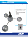
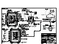
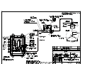
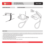
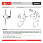
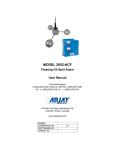
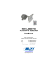
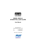
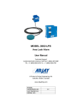
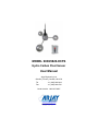
MODEL 9830/9820-HCFS Hydro Carbon Float Sensor User Manual Arjay Engineering Ltd. Oakville (Toronto), Canada, L6H 6C9 Tel . Fax. ++1 (905) 829-2418 ++1 (905) 829-4701 North America 1-800-387-9487 www.arjayeng.com [email protected] 9830-HCF Floating Oil Spill Alarm Reliable monitoring of sumps and containments for oil spills Over 30 years of Arjay’s field proven HF capacitance technology has been applied to the 9830-HCF Oil Monitor. The unique floating sensor continuously monitors for the accumulation of oil at the water surface. • Floating sensor follows changing water levels • Alarms on petroleum, synthetic, and vegetable oils • Potted stable sensor eliminates nuisance alarms 9830-HCF The 9830-HCF sensor monitors the surface dielectric and locks in on the capacitance of the water. Oil that separates to the surface changes the capacitance field and activates the relay alarms. This unit is normally used in sumps or containments where oil is not typically present. An upstream leak or spill that accumulates in the sump will alarm the monitor. The floating design allows the unit to track the changing water level in the sump and immediately alert operators, pumps or valves. Features and Benefits Technical Specifications - Control Unit • stable tri-float design follows level changes • adjustable time delay and sensitivity to eliminate nuisance alarms • remote electronics via standard twisted pair • available with Intrinsic Safety Barrier for Hazardous Locations • waterproof PVC and SS wetted parts allow for use in harsh environments • unit also alarms on dry sump conditions to shut down pumps • capacitance technology responds to all types of oils and separated liquids of similar dielectrics • alarms at 6mm separated surface oil The electronic components are mounted safely above the water level. The unique PMC circuit design, exclusive to Arjay, immediately converts the sensor signal to a frequency pulse for furtherance to the controller. Operating Temperature Power Input Alarm Relay Standards Enclosure Range -20˚C to 50˚C 24 vdc or 110 vac or 220 vac 5 amp, DPDT, dry UL, CSA, Entela Type 4X polycarbonate Alarms at 6mm oil Technical Specifications - Float Sensor Operating Temperature Wetted Parts I.S. Approval The Arjay Level Ease controller can be used where oil thickness indication or CE declaration is required. Refer to Model 2114-HCF. 0˚C to 50˚C PVC and 304SS CSA Class 1, Zone 2, Div 2, Groups A,B,C,D (when ordered with Intrinsic Barrier Option) All calibration, control relays and power wiring is available at the main control unit. This can be safely mounted up to 1 km away from the sump. Arjay SS-06 Arjay Engineering Ltd. 2851 Brighton Road Oakville, Ontario Canada L6H 6C9 tel fax N. America email web ++1 905-829-2418 ++1 905-829-4701 1-800-387-9487 [email protected] www.arjayeng.com Model: 9830/9820-HCFS 9830-9820HCFSum27.doc Rev: 2.7 Model 9830/9820 HYDROCARBON FLOAT SENSOR A. System Description The ARJAY Hydrocarbon Float Sensor provides a means for detecting hydrocarbon spills and separations on water. The ARJAY Tri-float contains a capacitance sensor that monitors the surface of the water. Water has a high dielectric constant, which results in a high capacitance reading. When oil (or a similar hydrocarbon) separates to the surface of the water, the ARJAY Tri-float rises above the water to the top of the oil. The capacitance sensor then 'sees' the oil on the surface. The dielectric of the oil is substantially lower than water, which results in a dramatic decrease in capacitance. The remote-mounted ARJAY 9830/20 controller monitors the capacitance change at the Tri-float and activates a relay contact for use with alarms, pumps, valves, etc. The unit requires at least 1/4" (6 mm) of hydrocarbon to alarm. The complete 9830 system consists of the float unit, the PMC card, and the 9830 controller. The complete 9820 system consists of the float unit and 9820 controller. The float unit is constructed with a PVC sensor pod and 3 stainless steel floats. The support arms are stainless steel. Co-axial cable extends from the sensor to the PMC card, which is mounted in a junction box safely away from the water level. The PMC card translates the capacitance signal from the sensor into a frequency pulse, which can then be transmitted up to one mile to the 9830 controller via 2-wire shielded cable. For 9820 applications the coax cable extends from the sensor directly to the 9820 controller and is limited to the 35 ft of coax cable supplied. B. Controller Installation Examine the instrument for possible shipping damage. IMPORTANT: If for any reason it is determined that parts should be returned to the factory, please notify the nearest ARJAY sales representative prior to shipment. Choose the mounting location in accordance with good instrument practice. Extremes of ambient temperature and vibration should be avoided (see specifications and installation drawing). The 9830 controller may be mounted up to one mile from the PMC card using 16 or 18 gauge, 2wire SHIELDED cable. The distance between the 9820 controller and sensor is restricted to within the 35 feet of coax cable supplied. Do not coil the coax cable. Any excess cable should be cut back. C. Sensor Installation The Tri-float sensor is supplied with 35 feet of coaxial cable between the float and the PMC junction box. As the float rises, the cable will hang into the water. Therefore, minimal water level change is preferred to reduce the stress pulling the sensor. The sensor should be placed in an area of calm or protected water. The 9830 junction box or 9820 controller should be mounted above the water level and in a protected area. NOTE: To ensure proper operation and electrical safety, make sure the 9820 or 9830 enclosure and the 9830 junction box is/are electrically grounded. There is a green ground screw at bottom of the 9830 junction box. -2- Model: 9830/9820-HCFS D. 9830-9820HCFSum27.doc Rev: 2.7 Operational Mode All ARJAY systems are designed so that the mode of operation (either low level fail safe or high level fail safe) may be readily changed in the field. For the ARJAY Float sensor, most applications will require the unit to be set in Low-Level Fail Safe. Under this condition, the relay will be energized all the time there is water. When the sensor 'sees' oil, the relay will de-energize signifying an alarm condition. E. Calibration Features All of the adjustments necessary for calibrating the ARJAY system are located on the main controller unit. The function of each is as follows: 1. Relay Switch: This two position fail safe switch will determine if the relay energizes or deenergizes on an alarm condition. Standard industrial practice suggests that the relay de-energize on alarm. Under this condition, any power failure to the unit causes the unit to signal an alarm condition. For the Float Sensor, set the switch to LOW failsafe to calibrate this sequence. 2. Time Delay: This circuit holds the relay in an energized position for a preset time of 1 to 20 seconds after the alarm condition has been reached. Maximum setting is position 7 for 20 seconds. Time delay on the unit will eliminate false or nuisance alarms caused by excessive turbulence, etc. For the Float Sensor, set the time delay to 10 seconds (position 5). DELAY SWITCH SETTING 0 TIME DELAY 0 seconds 1 2 seconds 2 4 seconds 3 6 seconds 4 8 seconds 5 10 seconds 6 15 seconds 7 20 seconds 8&9 Not used and act as 0 seconds. 3. Sensitivity: This 10-position switch determines the capacitance change required to cause the unit to alarm. Most applications require the setting to be adjusted to 1. With the setting at 1, a minimal amount of oil on the water surface will cause an alarm. A higher adjustment will increase the amount of oil required to cause an alarm (maximum position setting is 7). **INCREASING THE NUMBER WILL DECREASE SENSITIVITY** -3- Model: 9830/9820-HCFS 4. 9830-9820HCFSum27.doc Rev: 2.7 Hi/Low Dielectric: For calibration ease, the unit may be calibrated under a normal or alarm condition. Since the float is typically monitoring water as the normal condition, the unit would be calibrated in the HI dielectric position because the sensor is 'seeing' water (the high dielectric fluid) during calibration. 5. Calibrate: The Arjay 9830/20 provides a Push Button calibration feature for automatic calibration. F. Calibration (Set-up) With the instrument installed and wired per the installation drawing, the unit may now be powered up. The status led should be green indicating that power is on and the unit has no fault conditions. If the status led is red then the unit is showing a fault. Check to make sure the 9830 unit is properly wired to the pulse card. A wiring fault or pulse card failure would cause the status led to be red. Check the wiring for continuity and proper polarity. With the status led in green and the Tri-float in place on water, the unit may now be calibrated. Confirm the following switch positions: Relay in LOW Time Delay set to 10 seconds (position 5) Sensitivity set to position 1 Dielectric set to High Push the CALIBRATE button and hold until the status led goes red. Release the button. The status led should now be green and flashing on and off showing that the unit is in calibration mode. Push the calibration button one more time until it goes red. Release the button. Calibration is now complete and the STATUS led should be green and the alarm status led should be red showing that the relay is energized under normal conditions. Verify the operation by lifting the sensor out of the water a few inches. This will simulate the sensor “seeing oil”. After 10 seconds the relay will de-energize and the red alarm led will go off. Lower the sensor back onto the water and the relays will energize, and red alarm led will come on. The system is now verified and in operation. FOR ANY FURTHER QUESTIONS OR CONCERNS, CALL THE TECHNICAL HOTLINE AT: 1-800-387-9487 -4- Model: 9830/9820-HCFS G. 9830-9820HCFSum27.doc Rev: 2.7 TROUBLESHOOTING **Under normal conditions the status light on 9830 electronics (inside enclosure) should be Green and relay light should be Red. ** CONDITION 1. No indicators on at powerup 2. Status indicator is RED (Fault Condition) DO THIS Check power to unit Make sure power applied is as specified for the unit. (e.g. 120VAC) If power is ok, check the fuse. If the fuse is blown, call an Arjay representative to analyze why the fuse has blown. Make sure there is a PMC 2000 card mounted in the remote junction box. This indicates that the controller is not receiving a signal from the pulse card (PMC 2000) is weak, unstable, out of legal range, or is not present. Verify that the polarity of the two wire shielded connection is correct such that “+” at controller to “+” at pulse card (PMC 2000) and “-“ at controller to “-“ at pulse card (PMC 2000). Measure with DC volt meter across “+” and “-“ at pulse card (PMC 2000), it should read positive 9-10 Volts when plugged in. Make sure there is no break in the wiring between controller and PMC 2000 card. Disconnect probe (sensor) from “p” terminal of pulse card (PMC 2000). Verify if status LED goes to Green. Replace the PMC 2000 card with a spare if available. -5- Model: 9830/9820-HCFS 3. False alarms 9830-9820HCFSum27.doc Rev: 2.7 Add some time delay to unit. If coax cable is used from sensors to pulse card (PMC 2000), make sure it is not coiled (may cause an increase in inductance). Make sure there is no outside interference that may be causing false alarms such as an agitator, high voltage interference, or input flow to the tank affecting the probe. Adjust the sensitivity switch to next setting to decrease the 9830’s sensitivity. Test sensor after the setting has been increased to make sure the sensor can still reliably sense the presence of liquid. Make sure separator or grease trap is filled with water. -6-