1
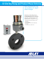
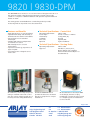
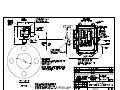
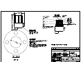
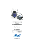
MODEL 9820/9830-DPM DRY PUMP MONITOR User Manual Arjay Engineering Ltd. Oakville (Toronto), Canada, L6H 6C9 Tel . Fax. ++1 (905) 829-2418 ++1 (905) 829-4701 North America 1-800-387-9487 www.arjayeng.com [email protected] 9820| 9830-DPM In-Line Dry Pump and Product Phase Detector Pipe monitoring for dry run conditions or liquid phase changes Over 30 years of Arjay’s field proven HF capacitance technology has been applied to the 9820/9830-DPM pipe monitor. The unique in-line sensor continuously monitors for the change from a wet to dry condition or a liquid change from one dielectric to another. • capacitance technology responds to any liquid type • no moving parts • remote alarm unit mounts safely away from pipe • no intrusion into stream flow 9820 | 9830-DPM The 9830-DPM sensor monitors a cross sectional area of the pipe and locks in on the capacitance field of the fluid passing through. A change toward a dry condition or a liquid of a different dielectric will upset the capacitive field and initiate an alarm. The sensing plates are embedded into a wafer flange which provides monitoring without any intrusion into the stream flow Features and Benefits Technical Specifications - Control Unit • wafer flange sensor for easy installation • adjustable time delay and sensitivity to eliminate nuisance alarms from bubbles • remote electronics via standard twisted pair • available with Intrinsic Safety Barrier for Hazardous Locations • PVC wetted parts for corrosive environments • capacitance technology responds to all types of liquids • non-intrusive sensor design does not restrict flow All calibration, control relays and power wiring is available at the main control unit. This can be safely mounted up to 1 km away from the sump (9830 version). Operating Temperature Power Input Alarm Relay Standards Enclosure Optional -20˚C to 50˚C 24 vdc or 110 vac or 220 vac 5 amp, DPDT, dry UL, CSA Type 4X, IP65 Lights and Buzzer Technical Specifications - Sensing Probe Operating Temperature Approval The Model 9820-DPM version provides the electronics mounted directly to the probe for compact installations. -60˚C to 50˚C CSA Class 1, Zone 2, Div 2, Groups A,B,C,D (also available with an Intrinsic Barrier Option on the 9830 verion) On the 9830 version the unique PMC circuit design, exclusive to Arjay, immediately converts the sensor signal to a frequency pulse for furtherance to the controller. Arjay SS-06 Arjay Engineering Ltd. 2851 Brighton Road Oakville, Ontario Canada L6H 6C9 tel fax N. America email web ++1 905-829-2418 ++1 905-829-4701 1-800-387-9487 [email protected] www.arjayeng.com MODEL DOCUMENT TYPE DOCUMENT FILE NAME REV. 9820/9830-DPM USER MANUAL 9820-30DPMum12.DOC 1.2 CREATE DATE REV. DATE PRINT DATE 12/01/2009 3:20:00 PM 12/07/2009 9:29 AM 12/07/2009 9:29:00 AM TABLE OF CONTENTS 1.0 2.0 3.0 4.0 INSTRUMENT OVERVIEW............................................................................................ 3 1.1 FEATURES ....................................................................................................... 3 1.2 DESCRIPTION .................................................................................................. 3 INSTALLATION .............................................................................................................. 3 2.1 CONTROLLER .................................................................................................. 3 2.1 SENSOR ........................................................................................................... 3 2.2 INSTALLATION TIPS ........................................................................................ 4 START UP AND CALIBRATION .................................................................................... 5 3.1 CONTROL AND FUNCTION SWITCHES ........................................................ 5 3.1.1 Failsafe ........................................................................................................ 5 3.1.2 Time Delay ................................................................................................... 5 3.1.3 Sensitivity ..................................................................................................... 5 3.1.4 Dielectric ...................................................................................................... 5 3.2 CALIBRATION................................................................................................... 5 TROUBLESHOOTING ................................................................................................... 6 HARDWARE REV. SOFTWARE REV. 1.0 9820_06 and higher Page 2 of 7 MODEL DOCUMENT TYPE DOCUMENT FILE NAME REV. 9820/9830-DPM USER MANUAL 9820-30DPMum12.DOC 1.2 CREATE DATE REV. DATE PRINT DATE 12/01/2009 3:20:00 PM 12/07/2009 9:29 AM 12/07/2009 9:29:00 AM 1.0 INSTRUMENT OVERVIEW 1.1 FEATURES 1.2 Push button calibration RF technology (ignores coating) Arjay pulse card system for simple safe remote control, calibration and maintenance Interchangeable and expandable components Standard time delay Hi/Low failsafe select Sensitivity adjustment and calibration features Optional lights, override switches, audio alarms, etc. are available No moving parts DESCRIPTION The ARJAY Dry Pump System comprises of the ARJAY Level-Ease Model 9820/30 control unit and a pump or pipe mount sensor. Typically, the sensor is mounted between the pump intake flange and the pipe flange although alternate sensor styles and mounting locations may be applicable. The system monitors for the presence and/or absence of fluid in a process line or pump. Under normal operating conditions the pipe will be full of fluid. The sensor will read a high capacitance. When the fluid level drops in the line, the capacitance will lower and the sensor will indicate an alarm condition. The control unit relay will switch to provide a visual alarm, signal a control system, or directly shut down a pump. 2.0 INSTALLATION 2.1 CONTROLLER Examine the instrument for possible shipping damage. IMPORTANT: If for any reason it is determined that parts should be returned to the factory, please notify the nearest ARJAY Sales Representative prior to shipment. Choose the mounting location in accordance with good instrument practice. Extremes of ambient temperature and vibration should be avoided (see specifications). 2.1 SENSOR The ring flange sensor can be mounted in a vertical or horizontal position. Consideration must be given to the presence and absence of fluid during an alarm condition. If an upstream abnormal condition causes a lack of fluid supply to the pump, the sensor must be situated such that it will be affected by the lack of fluid directly within the sensor. The ring flange sensor is designed in accordance with the ANSI ISO # sizing specifications. The sensor is constructed of PVC (alternate materials are available for specialty applications) and should be mated between raised flat faced flanges. Where specialty piping is used (i.e. Victaulic) mount the sensor ONLY in accordance with manufacturer’s specifications. HARDWARE REV. SOFTWARE REV. 1.0 9820_06 and higher Page 3 of 7 MODEL DOCUMENT TYPE DOCUMENT FILE NAME REV. 9820/9830-DPM USER MANUAL 9820-30DPMum12.DOC 1.2 CREATE DATE REV. DATE PRINT DATE 12/01/2009 3:20:00 PM 12/07/2009 9:29 AM 12/07/2009 9:29:00 AM 2.2 INSTALLATION TIPS Once the two mating flanges are joined to the pipe, the method for joining three flanges together is as follows: 1. Make sure that all the bolt holes of the matching flanges match up. 2. Insert all bolts 3. Make sure that the faces of the mating flanges are not separated by excessive distance prior to bolting down the flanges. Make sure the bolt holes align with mating flanges. 4. The bolts on the plastic flanges should be tightened by pulling down the nuts diametrically opposite each other using a torque wrench. Complete tightening should be accomplished in stages and the final torque values in the following table should be followed for the various sizes of flanges. Uniform stress across the flange will eliminate leaky gaskets. *Based on using flat faced PVC flanges, a full face neoprene gasket, well lubricated hardware, tightening in the proper pattern and applying torque in small increments. For raised face flange assemblies, and PVC to metal flange (or other materials) the above torque recommendations may vary. The sensor junction box is potted to the ring sensor. DO NOT attempt to re-align the sensor junction box as this will break the potted wiring and render the unit inoperable. FLANGE SIZE (INCHES) RECOMMENDED TORQUE (FT.LBS)* ½-1½ 2–4 6–8 10 12 – 24 15 30 50 70 100 HARDWARE REV. SOFTWARE REV. 1.0 9820_06 and higher Page 4 of 7 MODEL DOCUMENT TYPE DOCUMENT FILE NAME REV. 9820/9830-DPM USER MANUAL 9820-30DPMum12.DOC 1.2 CREATE DATE REV. DATE PRINT DATE 12/01/2009 3:20:00 PM 12/07/2009 9:29 AM 12/07/2009 9:29:00 AM 3.0 START UP AND CALIBRATION 3.1 CONTROL AND FUNCTION SWITCHES Set up the control and function switches as follows: 3.1.1 Failsafe Put the selector in the "LOW FAILSAFE" position. This will keep the relay energized during a normal pump full situation. On alarm; the relay will de-energize. A power failure will also cause the relay to de-energize, signaling an alarm condition. 3.1.2 Time Delay This will delay an alarm condition until the determined time has elapsed. By setting this to 10 seconds, the controller will shut the pump off after 10 seconds of a dry pump situation. Bubbles and air locks passing through the system will thereby be ignored. 3.1.3 Sensitivity This selector switch determines the amount of fluid level change required to cause an alarm. Setting the switch to "1" will offer the greatest sensitivity. **INCREASING THE NUMBER WILL DECREASE SENSITIVITY** 3.1.4 Dielectric The dry pump monitor should be calibrated during a full pipe condition. The switch should be set to "HI" for this calibration. 3.2 CALIBRATION With the unit wired as per the drawing, power on the unit. The status LED should be green indicating that power is on and unit is getting no fault conditions. If the status led is red then unit is showing a fault. Check to make sure unit is properly wired to the pulse card. A wiring fault or pulse card failure will cause the status LED to be red. Check the wiring for continuity and proper polarity. To calibrate, verify the above function switch positions. With the pipe confirmed full, push the CALIBRATE BUTTON. The status LED will turn red momentarily. Release the button. The status led should be green and flashing on and off showing that it is in calibration mode. Push the calibration button one more time until it goes red. Release the button. Calibration is complete and status LED should be green and alarm status LED red showing that the relay is energized under normal conditions. Verify the operation by causing the pipe to run dry within the sensor. NOTE: Closure of a local valve may not necessarily cause the pipe to run dry unless air is introduced into the line. HARDWARE REV. SOFTWARE REV. 1.0 9820_06 and higher Page 5 of 7 MODEL DOCUMENT TYPE DOCUMENT FILE NAME REV. 9820/9830-DPM USER MANUAL 9820-30DPMum12.DOC 1.2 CREATE DATE REV. DATE PRINT DATE 12/01/2009 3:20:00 PM 12/07/2009 9:29 AM 12/07/2009 9:29:00 AM 4.0 TROUBLESHOOTING **Under normal conditions the status light on 9830 electronics (inside enclosure) should be Green and relay light should be Red. ** CONDITION 1. No indicators on at powerup DO THIS 2. Status indicator is RED (Fault Condition) Check power to unit Make sure power applied is as specified for the unit. (e.g. 120VAC) If power is ok, check the fuse. If the fuse is blown, call an Arjay representative to analyze why the fuse has blown. Make sure there is a PMC 2000 card mounted in the remote junction box. This indicates that the controller is not receiving a signal from pulse card (PMC 2000) and is weak, unstable, out of legal range, or is not present. Verify that the polarity of the two wire shielded connection is correct such that “+” at controller to “+” at pulse card (PMC 2000) and “-“ at controller to “-“ at pulse card (PMC 2000). Measure with DC volt meter across “+” and “-“ at pulse card (PMC 2000), it should read positive 9-10 Volts when plugged in. Make sure there is no break in the wiring between controller and PMC 2000 card. Disconnect probe (sensor) from “p” terminal of pulse card (PMC 2000). Verify if status LED goes to Green. Replace the PMC 2000 card with a spare if available. HARDWARE REV. SOFTWARE REV. 1.0 9820_06 and higher Page 6 of 7 MODEL DOCUMENT TYPE DOCUMENT FILE NAME REV. 9820/9830-DPM USER MANUAL 9820-30DPMum12.DOC 1.2 CREATE DATE REV. DATE PRINT DATE 12/01/2009 3:20:00 PM 12/07/2009 9:29 AM 12/07/2009 9:29:00 AM 3. False alarms Add some time delay to unit. If coax cable is used from sensors to pulse card (PMC 2000), make sure it is not coiled (may cause an increase in inductance). Make sure there is no outside interference that may be causing false alarms such as an agitator, high voltage interference, or input flow to the tank affecting the probe. Adjust the sensitivity switch to next setting to decrease the 9830’s sensitivity. Test sensor after the setting has been increased to make sure the sensor can still reliably sense the presence of liquid. Make sure separator or grease trap is filled up with water above the white Teflon (sensing area) of probe. HARDWARE REV. SOFTWARE REV. 1.0 9820_06 and higher Page 7 of 7