1
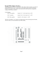
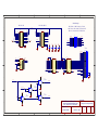
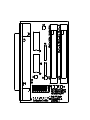
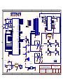
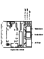
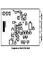
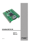
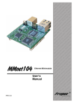
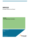
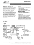
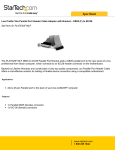
Dongle DVR
User Manual
Link Communications, Inc.
1035 Cerise Rd.
Billings, MT 59101-7378
(406) 245-5002
http://www.link-comm.com
Introduction:
Introducing the Dongle DVR digital voice recording system for many of the RLC repeater
controller family. The new module can be interfaced with the RLC-2/2a, RLC-3, RLC-Club,
RLC-Club Deluxe and the RLC-Club Deluxe II controllers. This new module provides a method
of recording and non-volatile storing of voice prompts and messages.
The Dongle DVR can be ordered in two configurations
- 8 Minutes total record time
Audio roll-off at 3.4 KHz
- 16 minutes total record time
Audio roll-off at 1.7 KHz
The Dongle DVR emulates the RLC-DVR1 digital voice recorder with the following exceptions.
- No Public mail is supported
- No Private mail is supported
- Only 91 general message slots
- No RS-232 port for uploading data files
On the RLC-Club Deluxe II controller, the DVR takes Port 6. Refer to your Deluxe II manual for
the correct jumper settings on Port 6.
The prompting tracks (Tracks 250, 251, 252, 253) are pre-recorded. If you erase these tracks,
you will need to re-record the prompting tracks with your own audio.
Features such as track prompting and over the air testing are supported. The Dongle DVR does
not require record memory back-up with a battery or external DC source. All messages are stored
in non-volatile eeprom memory. Tracks can only be written and erased over 100,000 times.
The Dongle DVR is housed in a DB-25 hood and contains a 16 bit microprocessor and a digital
record chip. Handle with care as this is a static sensitive device. Reverse power protection is
included and the internal +12V is fused utilizing a poly-resettable fuse. No other connections
other than +12V and a DB-25 for the controller interface is needed.
Do not plug the Dongle DVR into any other DB-25 connector other than the RLC-DVR1 interface.
Page 1
Dongle DVR Adapter Interface:
When using the RLC-2/2a, RLC-3 and the RLC-Club (without a Deluxe interface) you will need
the Dongle DVR adapter board. This module provides all the signals needed for the Dongle
DVR to work properly. On the module is an 8 position DIP switch that allows configuration
settings for the different controllers.
Switch Settings:
RLC-2/2a controller:
Switch 1,3,5,7 = ON: Switch 2,4,6,8 = OFF
RLC-3 controller:
Switch 1,3,6,8 = ON: Switch 2,4,5,7 = OFF
RLC-Club controller:
Switch 2,4 = ON: Switch 1,3 = OFF
The RLC-2/2a and RLC-3 use Connector JP2 (Right Angle connector that plugs into the board)
The RLC-Club uses JP1 and included 26 pin cable assembly.
Page 2
Connection Instructions:
1) Power the controller off
2) Plug the Dongle DVR into the DB-25 connector. If no DB-25 connector is available, then
plug the Dongle DVR Adapter board into the controller, and then plug the Dongle DVR in.
3) Wire +12V to the power plug (provided) with center pin positive, and outer pin as ground.
4) Apply power to both the controller and the Dongle DVR module
- The Power LED should light on the Dongle DVR module
5)Enable the DVR-1 in the controller
- RLC-2/2a Controllers:
Command 153:
- RLC-Club Controllers:
Command 182:
- RLC-3 Controllers:
Command 182:
153 1
182 1
182 1
6) You can now record and playback from the DVR
- RLC-2/2a Controllers:
- Playback Command:
- Record Command (Prompted)
- Erase Command:
Command 154
Command 155
Command 156
- RLC-Club and RLC-3 Controllers:
- Playback Command:
- Record Command (Prompted):
- Record Command (Non-Prompted):
- Erase Command:
Command 173
Command 172
Command 171
Command 174
7) Internal prompting tracks help in the recording process
Track 250: Please Record Your Message Now
Track 251: Your message is Stored
Track 252: Your Message is erased
Track 253: Invalid Message Track
Prompting tracks are limited to either 5 or 10 seconds depending on the DVR record length.
8) Tracks 0 to 90 are time limited tracks
8 Minute DVR - Tracks are 5 seconds each
16 Minute DVR - Tracks are 10 seconds each
9) Tracks 100 to 190 bypass the time limiting. If you record more than a tracks length, you will
overwrite the track(s) following. Use caution when recording tracks 100 to 190.
Page 3
10) For Over the Air recording (Used for signal strength measurements), the track length is
treated like a normal audio track in length. When the user issues the command, the Dongle DVR
will record the incoming audio, and when the user unkeys the radio, will immediately play the
recorded message back.
- RLC-2/2a Controllers:
- RLC-Club and RLC-3 Controllers:
Command 163
Command 170
11) When watching the Dongle DVR, the following LED’s will indicate its functionality.
- When the DVR is powered, the Power LED will light
- When the DVR is playing back, the Play LED will light
- When the DVR is recording, the Rec. LED will light
- When the DVR is erasing, both Play and Record LED's will flash
12) When adjusting the Dongle DVR, the following pots are used. The pots are set-up so 12 oclock position is about normal.
** Note **
Adjust the levels so they sound good to you. If the record level is adjusted to high, the audio will
sound clipped when played back, at any Playback adjustment point.
- Record level is adjustable using the REC pot on the Dongle DVR
- Playback Level is adjustable using the Play pot on the Dongle DVR
Page 4
Hardware Schematics:
Page 5
1
2
3
4
5
6
Switch Settings
RLC-CLUB
RLC-2/2a, RLC-3
RLC-Club: 1,3-Off, 2,4-On, 5,6,7,8-NA
RLC-2/2a: 1,3-On, 2,4-Off, 5,7-On, 6,8-Off
RLC-3: 1,3-On, 2,4-Off, 5,7-Off, 6,8-On
D[0..7]
A
JP1
+5V
R1
4.7K
D1
D3
D5
D7
CS
A1
+5V
JP2
1
3
5
7
9
11
13
15
17
19
21
23
25
CTRL_DVR
+12V
D0
D2
D4
D6
2
4
6
8
10
12
14
16
18
20
22
24
26
D0
D2
D4
D6
A0
A2
R2
4.7K
AUDIO1
+5V
DVR_CTRL
1
3
5
7
9
11
13
15
17
19
21
23
25
+5V
IDC26
D1
D3
D5
D7
2
4
6
8
10
12
14
16
18
20
22
24
26
S1
WRITE
CS_DVR1
READ
CS_DVR2
RW
AUDIO2
AUDIO1
+5V
CS_RLC3
IDC26
+5V
C1
0.01uF
+5V
C2
0.01uF
AUDIO2
+5V
C3
0.01uF
1
2
3
4
5
6
7
8
16
15
14
13
12
11
10
9
U3
CS
1
2
3
+5V
U1
A
B
C
6
4
5
OE1
OE2A
OE2B
8
GND
16
VCC
10
+5V
15 CS_DVR1
14 CS_DVR2
13
12
11
10
9
7
Y0
Y1
Y2
Y3
Y4
Y5
Y6
Y7
OUTPUT0
OUTPUT1
OUTPUT2
OUTPUT3
OUTPUT4
OUTPUT5
OUTPUT6
OUTPUT7
74HC138M
HC244
11
13
15
17
8
6
4
2
19
1
A8
A7
A6
A5
A4
A3
A2
A1
OE2
OE1
Y8
Y7
Y6
Y5
Y4
Y3
Y2
Y1
VCC
20
74HC244M
D0
D1
D2
D3
D4
D5
D6
D7
+5V
HC244
DVR_CTRL
CTRL_DVR
J1
DB25RAF
OUTPUT0
OUTPUT1
OUTPUT2
OUTPUT3
OUTPUT4
OUTPUT5
OUTPUT6
OUTPUT7
U2
10
GND
9
7
5
3
12
14
16
18
HC574
SW DIP-8
C4
0.01uF
B
A0
A1
A2
D0
D1
D2
D3
D4
D5
D6
D7
9
8
7
6
5
4
3
2
HC574 11
1
GND
D8
D7
D6
D5
D4
D3
D2
D1
Q8
Q7
Q6
Q5
Q4
Q3
Q2
Q1
LE
OE
VCC
12
13
14
15
16
17
18
19
DVR_CTRL
20
+5V
74HC574M
CTRL_DVR
+5V
13
25
12
24
11
23
10
22
9
21
8
20
7
19
6
18
5
17
4
16
3
15
2
14
1
B
26
27
C
14
C
A
RW
U4A
74HC00M
1
3
READ
2
CS_RLC3
7
14
+5V
U4B
74HC00M
4
6
5
+5V
14
7
14
+5V
U4D
74HC00M
12
11
8
WRITE
10
7
13
U4C
74HC00M
9
7
Link Communications, Inc.
D
Description
1035 Cerise Rd, Billings, Montana 59101
Dongle DVR Adapter Module
Phone: +406-245-5002 Fax: +406-245-4889
Drawing Number
Date
Adapter Module
1
2
3
4
March 11, 2004
5
Revision
Sheet
Total
A
1
1
6
D
2
3
+3.3V
GND
DS1818
R7
47K
+5V
IRQ
R8
47K
Inputs
B
INPUT0
INPUT1
INPUT2
INPUT3
INPUT4
INPUT5
INPUT6
INPUT7
SMOD/TAGHI/BKGD
38
37
36
35
29
28
27
26
XIRQ/PE0
IRQ/Vpp/PE1
R/W/PE2
LSTRB/PE3
ECLK / PE4
MODA/PE5
MODB/PE6
DBE/PE7
6
5
4
3
2
1
80
79
VFP
PDLC0/DLCRx
PDLC1/DLCTx
PDLC2
PDLC3
PDLC4
PDLC5
PDLC6
PW0/PP0
PW1/PP1
PW2/PP2
PW3/PP3
PP4
PP5
PP6
PP7
69
PS0/RxD
PS1/TxD
PS2
PS3
PS4/SDI/MISO
PS5/SDO/MOSI
PS6/SCLK
PS7/CS/SS
V-FLASH
49
IOC0/PT0
IOC1/PT1
IOC2/PT2
IOC3/PT3
IOC4/PT4
IOC5/PT5
IOC6/PT6
PAI/IOC7/PT7
VREF/H
50
VREF/L
10
31
47
59
78
C
A8/D8/PA0
A9/D9/PA1
A10/D10/PA2
A11/D11/PA3
A12/D12/PA4
A13/D13/PA5
A14/D14/PA6
A15/D15/PA7
RST
17
VCC
VCCX
VCC
VCCA
VCCX
11
30
48
60
77
PAD0
PAD1
PAD2
PAD3
PAD4
PAD5
PAD6
PAD7
GND
GNDX
GND
GND
GND
76
75
74
73
72
71
70
10
5
+5V
RAC
PLAY_LED
REC_LED
61
62
63
64
65
66
67
68
U6
SN74AHCT1G08DBVT
4
7
8
9
12
13
14
15
16
IRQ
24
RAC
R5
47.5K
+3.3V
27
18
VCC_D
VCC_A
C9
10uF\10V
2
Vin
1
Vout
+3.3V
B
U4
LM3480IM3-3.3
C12
0.1uF
R11
1K
R9 1K
2
1
1
2
R12
47K
3
U7A
MC34072DW
+5V
LED0
Q1
2N7002
51
52
53
54
55
56
57
58
+5V
C13
0.01uF
MO
3
+5V
U8A
74LCX08DW
R13
47K
R14
47K
1
5
SS
MO_5V
6
4
U8B
74LCX08DW
+3.3V
DS2
R10 1K
DVR_INPUT
+5V
PLAY_LED
R15
1K
R23
100K
1
2
3
J2
+5V
6
7
2
1
2
3
SC
R16
47K
U8C
74LCX08DW
12
U8D
74LCX08DW
+3.3V
R17
47K
C
13
11
9
+5V
U7B
MC34072DW
10
8
LED0
Q2
2N7002
SS_5V
+3.3V
SC_5V
+3.3V
5
C14
0.01uF
R18
47K
FD1
FD2
FS1
CON3_SM
FLASH AND SYSTEM POWER
2
miniSMD075F/24
C10
10uF\20V
C17
0.1uF
Vin
Vout
+5V
+5V
1
C15
0.1uF
C16
1uF
BACKGROUND
PORT
R20
4.7K
BACK
3
F1
GND
U5
LM3480IM3-5.0
1
DS3
1
3
5
J4
1
3
5
2
4
6
2
4
6
Link Communications, Inc.
Phone: +406-245-5002 Fax: +406-245-4889
IDC6
+VINP
Drawing Number
Date
Dongle DVR
2
3
Description
1035 Cerise Rd, Billings, Montana 59101
RST
LED0
1
25
26
XCLK
GND_D
GND_A
GND_A
GND_A
+VINP
DS1
REC_LED
+VINP
1.5K
INT
RAC
A
SS
+5V
MO
MI_3V
SC
DVR_OUTPUT
27
MI_3V
+5V
VFP
+12V Input
R24
1
2
3
28
12 Minute Digital Voice Recorder
26
R22
100K
1
D1
DL4001
2
4
11
12
23
C5
1uF\10V
14
SS
MOSI
MISO
SCLK
C11
0.1uF
+VINP
D
U3
ISD4004-12MS
R2
4.75K
2
MO_5V
SC_5V
SS_5V
MC68HC912B32
J3
PCON
C8
0.1uF\10V
AM_CAP
NC1
NC2
NC3
NC4
NC5
NC6
NC7
NC8
NC9
NC10
NC11
C3
1uF\10V
7
BACK
C7
2200pF\10V
AN_IN-
13
14
32
RST
5
6
7
8
9
10
15
19
20
21
22
AUD_OUT
7
1
16
R4
47.5K
AN_IN+
3
RST
3
39
40
41
42
43
44
45
46
INPUT1
INPUT3
INPUT5
INPUT7
INPUT6
INPUT4
INPUT2
INPUT0
17
7
+5V
VCC
R21
9
R8
8
R7
7
R6
6
R5
4
R4
3
R3
2
R2
1
R1
V+
V+
CTS-745X101
13
25
12
24
11
23
10
22
9
21
8
20
7
19
6
18
5
17
4
16
3
15
2
14
1
OUTPUT0
OUTPUT1
OUTPUT2
OUTPUT3
OUTPUT4
OUTPUT5
OUTPUT6
OUTPUT7
INPUT0
INPUT1
INPUT2
INPUT3
INPUT4
INPUT5
INPUT6
INPUT7
C2
0.1uF\10V
7
2
EXTAL
R6
OUTPUT7
OUTPUT6
OUTPUT5
OUTPUT4
OUTPUT3
OUTPUT2
OUTPUT1
OUTPUT0
18
19
20
21
22
23
24
25
8
A0/D0/PB0
A1/D1/PB1
A2/D2/PB2
A3/D3/PB3
A4/D4/PB4
A5/D5/PB5
A6/D6/PB6
A7/D7/PB7
4
XTAL
8
U1
4
34
33
U2
R1
62.5K
J1
D Connector 25
C6
22pF
+5V
C23
0.01uF
14
C22
0.01uF
3
Y1
16MHz
C21
0.01uF
5
R3
10Meg
C20
0.01uF
Outputs
C4
22pF
C19
0.01uF
6
GND
C18
0.01uF
A
5
C1
1uF\10V
14
+5V
4
14
1
4
March 11, 2004
5
D
Dongle DVR
Revision
Sheet
Total
B
1
1
6