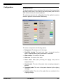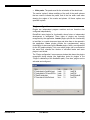
1
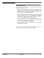
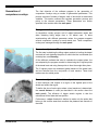
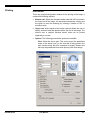
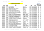
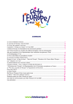
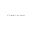
User Manual. Version 2.0
Written by:
Carlos Javier Ogayar Anguita.
Department of Forensic Medicine and Forensic Odontology.
Software Engineering Department.
Coordinated action ACC-286-CVI-2001.
Responsible researchers:
Aurora Valenzuela Garach.
Stella Martín de las Heras.
Juan Carlos Torres Cantero.
Contents
Introduction.................................................................................. 1
Overview....................................................................................... 2
Basic controls.............................................................................. 5
Main panel .................................................................................... 7
Scale ........................................................................................... 10
Dental cast management .......................................................... 12
Generation of comparison overlays ........................................ 13
Printing ....................................................................................... 15
Print to file.................................................................................. 22
Configuration ............................................................................. 25
Menus ......................................................................................... 28
Icon reference ............................................................................ 30
Shortcut keys............................................................................. 32
Glossary ..................................................................................... 33
Links ........................................................................................... 37
Introduction
Bite mark analysis is based on the uniqueness of the dentition that is
accurately recorded onto the skin or in an object when biting. However,
biting is a dynamic procedure involving two moving systems, maxilla and
mandible, and the reaction of the victim. Furthermore, bite mark
distortion can be also produced by anatomic location of the injury or by
the elasticity of the skin tissue. Therefore, a single dentition can produce
bite marks that exhibit variations in appearance. This complex evidence
emphasizes the necessity of applying new 3D graphic technologies to
bite mark analysis. Until now, the most common method for the
comparison process consisted in the generation of comparison overlays
from suspect’s teeth to compare with a life-sized photography of the bite
mark.
DentalPrint is an experimental software program developed at the
University of Granada (Spain). It allows one to generate different
comparison overlays from 3D dental cast images depending on the
pressure and the deviation of the biting. The procedure to generate the
comparison overlays is entirely automatic, hereby avoiding the bias of
observer’s influence.
DentalPrint 2.0
User Manual
1
Overview
The environment
The first step consists in getting familiar with the working environment of
the application. The user interface of DentalPrint works like any other
Windows application, so this shouldn’t be difficult.
The main window contains the working space and a number of panels
that provide access to the various options and commands of the
program. As is common in most applications, these panels can be
moved and connected to the borders of the window. Some panels only
allow for a horizontal placement of their elements, while others can be
placed vertically in the margins of the window.
The main panel is the principal tool of the application, since it contains
all the parameters that control the generation of the comparison
overlays. This panel can be connected to the left or right border of the
window, but can also float on top of the working space. It contains a
number of tabs that allow the user to select available pages with options
and parameters. Moreover, the panel can also be collapsed, leaving
more space to work with the document while still allowing access to its
tabs.
DentalPrint 2.0
User Manual
2
To expand or collapse the panel, one uses the button with the double
arrow (indicated in the figure in blue).
To close the main panel, press the button with the cross (indicated in
the figure in red), or use the option “Toolbars” in the menu “View”.
When a panel is closed, it is also possible to open it again using this
menu option.
First steps
To begin working with DentalPrint, it is necessary to have relevant data
files to work with. These files should be the result of scanning a dental
cast with any 3D capture device that generates valid output for
DentalPrint, i.e. that produces documents of a compatible file type. To
facilitate the exploration of DentalPrint’s features, your distribution of
DentalPrint might already include some example files with data from
mold scans.
•
To load a file, use the option “Open” in the menu “File”.
•
Once the file is loaded, the dental cast 3D image will appear in the
main window.
•
The main advantage of visualizing a dental cast in 3D, is that one
can obtain views from multiple viewpoints. It is possible to move and
rotate the dental cast, and one can zoom in on a selected region; to
do this, use the movement controls.
•
Besides these controls, other options include centering the dental
cast, clipping on a region of interest or changing the predefined
views using the advanced control options.
Before continuing it should be noted that it is possible to save the
applied changes using the options “Save” and “Save As” from the “File”
menu. Some file types may only be used when importing data and not
while exporting data (or the other way around); this depends on the
installed modules or plug-ins. In any case, it is recommend to work with
the DentalPrint’s own format (with extension “.dp”) since this format can
always be used for loading and saving. When you are working with a file
that is not in the application’s own format, it is advisable to save the data
in a new DP file and to work with that document from then on.
DentalPrint 2.0
User Manual
3
Working with the data
Once the 3D dental cast is loaded, it’s time to apply the required options
to calculate comparison overlays.
•
Primarily, it is necessary to set the parameters to obtain the biting
edges from the 3D dental cast. This process is described in the
following sections. The operation of the associated properties panel
can be found under the title parameter panel.
•
To personalize the obtained visualization, it is possible to make
various adjustments using the visualization parameters.
Furthermore, the sight of the 3D dental cast can be changed by
means of the visualization panel and the cast color.
•
The program supports the use of an editing scale (ABFO n°2 scale)
that aids in better perception of the dimensions of the teeth. It can
also be configured through the scale options.
•
When all the data is calculated, it is possible to print or export the
obtained prints as a bitmap.
To get to know the other options that the application offers, it is
recommended to study the other parts of this help guide.
DentalPrint 2.0
User Manual
4
Basic controls
The basic controls provide means to operate the camera, thus allowing
the visualization of the working dental cast in one way or another. These
controls are subdivided in basic camera options, advanced options and
visualization parameters.
Movement options
Move: Move the dental cast horizontally (x-axis) and vertically (yaxis) in a plane parallel to the camera plane. The position of the
mouse cursor upon releasing the mouse button will determine the
exact new position of the dental cast.
Rotate: Turn the camera around its focal point. The region of
movement is a sphere around this point. Horizontal movement will
correspond to a change in longitude; vertical movement
corresponds to latitude.
Zoom: Allows zooming, i.e. allows moving the camera towards
the object or away from it. The actual movement is a traveling in
depth, but for reasons of simplicity, this is presented as a zoom
function (the notion of a visual angle does not exist in the case of
parallel projection, so it would be impossible to provide an
authentic zoom anyhow). Move the mouse vertically to effectuate
the zoom.
Zone zoom: Click and drag with the mouse to select a region of
interest. When the mouse button is released, the window will be
reframed.
Advanced options
Center: Center the dental cast on screen without changing the
orientation of the camera.
Fit: Reestablish the initial camera position of the selected view.
This position provides a complete fit of the dental cast.
DentalPrint 2.0
User Manual
5
Views: Select one of the predefined views (Upper, Left, Right,
Anterior or Posterior).
Visualization mode: Select the visualization mode (wire frame,
solid, etc.). The available options depend on the installed
graphical plugins.
Visualization parameters
Cast alignment: Show the transformed dental cast, i.e.
positioned as such that the contact plane is parallel to the base
plane (the latter is the plane that includes the scale).
Show cast: Show the surface of the dental cast.
Show contour: Show the outline of the generated biting edges.
Show area: Show the area of the generated biting edges.
Show peaks: Show the calculated peaks (in different colors to
indicate whether or not the peaks belong to the clipping zone).
Show main peaks: Show the three peaks that were used to
calculate the contact plane.
Show planes: Show the planes of the current comparison
overlay. This option allows selecting three distinct planes (top
plane, contact plane and deepest plane), in addition to the
clipping area.
DentalPrint 2.0
User Manual
6
Main panel
The main panel is the principal tool of the application. It can be
expanded and collapsed, and it can be placed on either side of the main
window. It contains various subpanels that offer the following
functionality:
Parameter panel
The parameter panel gives access to all the parameter values of the
different overlays. It is divided in several sections that correspond to the
different steps in the generation of the comparison overlays. The button
next to the title of each section can be used to restore the default values
of the parameters in that section. To effectuate any change to these
variables, it is necessary to request the calculation of a new mark by
pressing the button “Accept changes”, located at the bottom of the
panel.
•
Overlay generation list: This list is used to select the overlay to
work with, i.e. the current set of parameter values. The buttons
below the list allow the creation of new overlays, or the copying or
deleting of existing ones.
•
Peaks computation: The first step in the calculation of the
orientation of the teeth consists in finding the highest points of the
3D dental cast. The points are defined by the following parameters:
•
−
Search distance (millimeters): The complete dental cast is
searched to find local maxima that are later combined to find
global maxima; the search radius determines the size of each
zone where a local maximum is calculated. When this number is
higher, computation will be faster and fewer peaks will appear.
Please note that the search zones (that are of cylindrical form)
will partially overlap to prevent the loss of information.
−
Slope (degrees): A slope with respect to the base plane is
determined in each surface point (including the peaks); when the
angle of inclination exceeds the threshold value that was set
here, the local maximum will be rejected.
Orientation: To keep the set of teeth correctly orientated, it might be
necessary to make a number of adjustments to the following
parameters:
−
DentalPrint 2.0
Iterations: Each time the set of teeth is reoriented, the maxima
need to be recalculated to obtain better results. This process
iterates as many times as specified here. Unless the dental cast
is very inclined (because of the processing by the scanner for
example), it is recommended to maintain a value of 1.
User Manual
7
−
Threshold distance (millimeters): It’s quite possible that some
of the main peaks of calibration are located very near to each
other, hereby causing an incorrect orientation of the whole. The
threshold distance prevents this by specifying the minimal
distance between the main peaks.
•
•
−
Clipping area: The clipping area is used to limit the region that
is searched for local maxima, hereby discarding the parts of the
dental cast that are not of interest.
−
Fitting angles (degrees): It is possible to make an additional
adjustment by setting the angles H and V. These allow rotating
the resulting planes clockwise. The H and V angles specify the
horizontal and vertical rotation respectively, as observed when
viewing the dental cast from behind.
Comparison overlays: The generation of the biting edges of the
dental cast occurs once the orientation is completed. It depends on
the values of the following variables:
−
Angle (degrees): The biting edges extend from the contact plane
downwards, up to the points where the slope of the surface
exceeds the cut angle.
−
Depth (millimeters): To avoid that the biting edges exceed a
certain depth, it can be limited using this parameter. The cut
height is measured from the contact plane in a downward
direction.
Comments: Press this button to open a dialog window where
additional comments about each overlay can be entered (as plain
text).
Visualization panel
This panel allows the modification of the visualization properties of the
dental cast. Currently only the management of dental cast material is
supported.
A material for a dental cast is a simple approximation of the visual
characteristics of the real-world equivalent.
The material selection box presents a list of available materials. The top
of the list shows the predefined materials; the materials at the bottom
(indicated as “User 1”, “User 2”, etc.) can be user-defined. To apply a
material click the “Apply” button or double click on its name.
When selecting one of the user-definable materials, the “Edit” button will
be activated. Through this button the “Edit material” window can be
opened. All changes to the user-defined materials are saved in the
DentalPrint 2.0
User Manual
8
configuration file of the application, and do therefore apply to all
documents (which material is selected however, is a setting that is
saved in the currently opened document).
Details panel
With this panel, different levels of detail (LODs) can be created to
visualize the dental cast using a lower resolution. This option is suitable
when working with a less powerful computer or in the case of complex
models. The disadvantage is however that the mark can’t be visualized
with a level of detail that is adequate; because the displayed surface
doesn’t represent the surface that was used during the calculations, the
two are no longer visually compatible.
A new level of detail can be initiated with the “New” button and an
existing level can be deleted by selecting it in the list and pressing
“Delete”.
To activate a level of detail, double click on it in the list.
When initiating a level of detail, the associated dialog window is used.
This window offers 3 ways to specify the new level of detail:
DentalPrint 2.0
•
Simple uniform generation: Generate a new model by sampling at
regular intervals (with the interval size specified in the text box
“Sample size”).
•
Simple non-uniform generation: Take samples in the original
positions of the grid that defines the base, but afterwards reduce
these samples according the specified width and depth divisors to
obtain the new model.
•
Multiple generation: Generate as much levels of detail as indicated
by progressively reducing the resolution. This option uses nonuniform sampling.
User Manual
9
Scale
The scaled ruler (ABFO’s scale) is a virtual representation that reflects
the scale of the dental cast. It will be visible on the final print exactly as it
is shown on the screen while working. The user can configure the scale;
it supports two units of length (cm, inch), it can be auto-adjusted to the
dental cast and it can be split in segments.
Scale options
Show/hide scale: Activate or deactivate working with the scale.
Unit of length: Switches between the British system (inches) and
the international system (centimeters).
Width: The width of the scale (in the selected unit).
Height: The height of the scale (in the selected unit).
Scale fitting: Auto-adjust the scale to the dimensions of the
dental cast.
DentalPrint 2.0
User Manual
10
Scale sections: The scale can have up to 4 visible sections (up,
bottom, left and right). This command allows activating and
deactivating of each of these sections.
Adjust scale: The dental cast is positioned with respect to the
scale by taking a reference point and placing this in the origin of
the scale. Since by default the right and inferior sections of the
scale are shown, this reference point is the bottom-right point of
the dental cast. When changing this point, the position of the cast
will also change.
Measure distances: Measure distances between two points on
the screen. Four measurement functions exist: between two
points, horizontal, vertical and rectangular (i.e. measure
horizontal and vertical at the same time). When using these
functions, it is essential that the camera plane is parallel to the
plane in which one wants to measure. This can be achieved by
selecting one of the predefined views before measuring, and
hereafter only using the functions “move” or “zoom” (but not
“rotate”) to position the 3D dental cast. Usually measurements are
made using the upper view.
To measure on top of the image, one has to click and drag from
source point to destination point. When releasing the mouse
button, a dialog window will appear with the measurement results.
DentalPrint 2.0
User Manual
11
Dental cast
management
Besides the ones offered by the main panel, various other options exist
that allow editing of dental casts. They are listed in this section.
Open or import casts. Data files that contain casts can be
opened or one of their casts can be imported into the current
document.
Save. When saving a document, all the associated casts,
comparison overlays and parameters are included.
Print. Print the document.
Save bitmap. Print the current document to a bitmap file.
Export. Copy the selected dental cast to a new document,
including the related data.
Delete cast. Allows deleting dental casts selectively.
Edit casts. The editing of the cast’s data occurs in a dialog
window where the associated information can be modified.
Rotate cast. The dental cast can be rotated in intervals of 90°.
DentalPrint 2.0
User Manual
12
Generation of
comparison overlays
The final objective of the software program is the generation of
comparison overlays using a number of geometrical parameters. This
process consists of number of stages, each of which with its associated
variables. This section outlines the complete generation process and
points to the relevant parameters. These parameters are further
specified in the section about the main panel.
Management of comparison overlays
A comparison overlay groups a set of related parameter values that
allow obtaining biting edges from a 3D dental cast. To allow
experimenting with different parameter values, the program supports
several comparison overlays for each dental cast. These comparison
overlays are managed through the main panel.
Parameter adjustment: The contact plane
The first step in obtaining the biting edges consists in leveling the dental
cast and as such obtaining the plane on which the bite is simulated (the
contact plane, see Glossary).
Of the different methods that exist to calculate the contact plane, the
one adopted by the program consists in determining the 3 highest points
of the dental cast and using those points to form the sought-after plane.
The 3 highest points are considered global maxima of the dental cast,
and are selected from the conjunction of local maxima. These local
maxima are also called peaks.
Parameter adjustment: Calculation of peaks
A local maximum with respect to a region is the highest point of the
dental cast within that region.
To define the size of each region where a local maximum is determined,
the search distance is used (as described in the section about the
main panel). The influence of bigger search regions is that the
calculations will be faster but less precise.
Furthermore, a slope threshold is defined to retain only the peaks that
belong to the surface areas that constitute the plateaus and summits of
the teeth.
DentalPrint 2.0
User Manual
13
Parameter adjustment: Calculation of the contact plane
Although the selection of the 3 highest peaks (or “main peaks”) may
seem trivial once the local maxima (or “candidate peaks”) are
determined, there are a few peculiarities about this process that greatly
influence the final result.
Firstly, one has to keep in mind that the 3 main peaks lie directly in the
surface where the bite is assumed. This means that, if one of these
points appears in the surface of a tooth that doesn’t intervene in the bite,
the resulting plane has to be conceptually wrong. To resolve this issue,
the program allows defining a clipping area that has a higher
probability to intervene in the bite.
Secondly, it’s quite possible that some of the main peaks are located to
close to each other, which can cause false results. This can be avoiding
through the threshold distance.
Finally, it is also possible to adjust the contact plane manually to adapt it
to a concrete situation, such as the simulation of a biting angle upon the
surface. This is regulated through the fitting angles.
Parameter adjustment: Generation of biting edges
Once the contact plane is determined, the comparison overlay can be
generated. For this final phase, it is required to specify parameters that
define how far the biting area extends from the contact plane towards
the dental cast. This is done through a maximal angle and depth.
DentalPrint 2.0
User Manual
14
Printing
Print window
This is the principal configuration window for the printing of the image. It
contains the following sections:
•
Bottom cast: Select the document dental cast that will be printed in
the lower part of the image, the associated comparison overlay and
the option to invert the drawing (by inverting a rotation of 180° is
actually meant).
•
Upper cast: Works equal as the bottom cast but allows the user to
specify a second cast that appears above the first in the image. The
second cast is optional because dental casts can be printed
separately or in pairs.
•
Options: The following presentation options are available:
−
DentalPrint 2.0
View: Select the view to print. This can be one of the predefined
views or the actual view (i.e. the view that is being used in the
main window when the print command is issued). Please note
that only the predefined views allow printing a life-sized image.
User Manual
15
•
DentalPrint 2.0
−
Scale: Determines the dimensions of the image that is sent to
the printer. This can either be life-sized dimensions or adjusted
to the size of the page. To obtain a print in landscape orientation,
setup the printer for that effect.
−
Reoriented cast: Show the cast orientated as such that the
contact plane (or actually any of the planes) is parallel to the
base plane.
−
Draw cast: Show the 3D dental cast of the teeth.
−
Draw contour: Show the outline of the bite mark.
−
Draw area: Show the area of the bite mark.
−
Draw peaks: Show the peaks as they appear in the working
area of the main window.
−
Draw main peaks: Show the main peaks.
−
Show clipping area: Show the clipping area.
Drawing options: The appearance of the different elements when
printing can be modified in the same way that the visualization of
documents can be configured. However, the set of values
maintained for printing is different than the set for working, given that
the requirements for these two cases are usually different. For
example, the background color for working (on screen) is typically
black, whereas for printing a white background is normally preferred.
User Manual
16
All these variables are saved in the configuration file of the
application. The last used values are therefore available between
execution runs.
•
DentalPrint 2.0
Advanced options: These options are related to the additional
items that are printed on the resulting page, and the composition of
that page. The following options are available:
−
Print additional information: Print text information related to
the dental cast and the generated overlay, formed by the items
that appear on the left side of this window.
−
Cast name: Print the name of the dental cast.
−
Cast size: Print the original dimensions of the dental cast (these
dimensions can be different from those of the printed image).
−
Comments about cast: Print the contents of the text field that
each dental cast possesses as additional information.
−
Overlay information: Print the properties of the selected
comparison overlay.
−
Parameters: Print the parameter values of the selected
comparison overlay.
−
Comments: Print the additional comparison overlay information.
−
Program version: Print the application version.
−
Print date: Print the current date.
−
Use grayscale for text: Use a shade of gray for the textual
information.
User Manual
17
•
−
Title color: This is the color used for the printing of the
parameter names.
−
Properties color: This is the color used for printing of the
parameter values.
−
Select font: Select the font used for printing the text. Also allows
selecting the font size, but please note that the application
doesn’t control the final size of the text area; this means that any
text that doesn’t fit on the page anymore will simply be cut off.
−
Margins: Specify the page margins (these are added up to any
margins already imposed by the printer).
Image: This section allows the user to modify the final appearance
of the image by flipping it horizontally and vertically. This operation is
not related to the rotations of the dental cast; the two can be freely
combined.
The icons that appear in this section serve to update the preview in
the upper-right part of the window. Whenever a configuration
parameter is modified, the button with the eye icon will appear to
allow updating of the preview image. Press the button with the lock
icon to make the preview image update automatically (the first
button is not necessary anymore in this mode and will not appear).
This system allows manual management of the preview because it
can be slow when working with complex models.
DentalPrint 2.0
•
Cast displacement: It is possible to modify the distance that is
maintained in between the two dental casts, and between the dental
casts and the scale. The horizontal and vertical distances control the
displacement of the dental cast(s) with respect to the reference point
of the scale. The distance in between casts is applied vertically. All
distances have to be entered in millimeters.
•
Scale: Show the scale in the image. The configuration window of the
scale contains the following parameters:
User Manual
18
•
−
Type: The type can be Editing Scale, Standard 5x5cm and
Custom. The first is the scale used when editing the document.
The second is a scale of 5x5cm placed in the bottom-left corner.
The custom scale allows adjusting all parameter values
individually.
−
Unit: Switch between centimeters and inches.
−
Width: The width of the scale.
−
Height: The height of the scale.
−
Scale fitting: Auto-adjust the width and height to the dimensions
of the dental cast.
−
Segments: Activate or deactivate the sections of the scale
(superior, inferior, left and right) and change the reference point
(by using one of the four corners).
Printer: In this section the selected printer is showed, together with
a button that opens a window to configure it.
The “Select” button in this configuration window allows the user to
change the printer and also allows him to change options specific to
this printer.
The advanced options offer the possibility to print in strips. This
printing mode divides the image in several segments or strips that
together constitute the final result. The size of a strip is measured in
millions of points. Since the decomposition in strips slows down the
print process, this option should only be used when you experience
problems with normal printing. This option is provided because of
compatibility problems and out-of-memory issues that occur with a
number of printers.
DentalPrint 2.0
User Manual
19
Print examples
This example shows two casts and uses 5mm horizontal and vertical
displacement, while maintaining 15mm distance in between both casts.
The margins are 0.5mm (on top of the margins of the printer). The paper
format used is A4, and the image was scaled to fit the paper size. The
upper cast is inverted.
DentalPrint 2.0
User Manual
20
This example shows a cast using editing view (it therefore doesn’t
appear life-sized). In this case, no separation towards the reference
point is used. The paper format used is also A4.
DentalPrint 2.0
User Manual
21
Print to file
Print to file window
The print to file window is equal to the normal printing window, except
that all the controls related to the printer are deactivated.
After confirming the print window by pressing the “Accept” button, a
window will appear that allows configuring the final size of the image in
pixels. The available options depend on whether actual size (1:1) is
used or editing view.
DentalPrint 2.0
User Manual
22
In the former case, the parameter that determines the number of pixels
in the image is the resolution, specified in dots per inch (dpi). This is
logical, given that the other editing program that will print the image
must use the same resolution to obtain a result in actual size.
In the other case, the dimensions can be directly specified in pixels.
Examples of print to file
This example shows a cast using the editing view. The original image is
much bigger; it was resized (and smoothed) for a correct presentation.
The background color is part of the bitmap.
DentalPrint 2.0
User Manual
23
This example shows a cast using the upper view in actual size (1:1) with
a resolution of 600x600dpi. Although the image was reduced here for a
correct presentation, the bitmap contains information at the original
resolution and allows printing in actual size (1:1) with any 2D graphic
editing software.
DentalPrint 2.0
User Manual
24
Configuration
Drawing options
The drawing options allow customizing of the colors of the elements that
are used on the screen, of the radii of the points (peaks) and of the line
width of the contours (of areas and planes).
The values are stored in the configuration file of the application and are
therefore applied to all documents indistinctively.
The colors correspond to the following options:
DentalPrint 2.0
•
Background: The background of the image.
•
Simplified drawing: The dental cast when it is moved when the
option “simplified drawing during movement” is activated.
•
Mark contour: The outline of the mark.
•
Mark area: The interior of the mark.
•
Plane colors: Each plane (including the clipping zone) can be
assigned its color.
•
Normal peaks: The color of the peaks when no clipping rectangle is
defined.
•
Discarded peaks: The color of the peaks discarded by the clipping
rectangle.
•
Selected peaks: The color of the peaks that are contained in the
clipping rectangle.
User Manual
25
•
Main peaks: The peaks used for the orientation of the dental cast.
The section “options” allows modifying of the radii of the small spheres
that are used to indicate the peaks, and of the line width used when
drawing the edges of the marks and planes. All these options are
specified in pixels.
Plugin configuration
Plugins are independent program modules and are therefore also
configured independently.
DentalPrint uses plugins for functionality where future or independent
development is anticipated. Three types of plugins are currently
recognized by the application. Loader plugins provide the functionality
to load files in a certain document type and allow them to be opened in
the application. Saver plugins provide the complementary saving
functionality for document types. Render plugins, finally, are responsible
for the 3D graphics display. Only one render plugin can be activated at
the same time, whereas the number of activated loader and saver
plugins is not limited.
The “Plugin configuration” menu opens a window that shows the plugins
recognized during startup (the application looks for plugins in the
“Plugins” subdirectoy of the installation path). From here, plugins can be
activated and configured.
DentalPrint 2.0
User Manual
26
The following plugins are distributed together with DentalPrint:
DentalPrint 2.0
•
LoadPIX: To load documents in the Pix format (extension ‘.pix’),
as used by the PICZA scanner.
•
LoadDP / SaveDP: Plugins to load and save documents in the
programs own format (extension ‘.dp’).
•
OpenGLRender: Render plugin that uses the systems OpenGL
driver to display the 3D graphics.
User Manual
27
Menus
File menu
•
Open: Open a document compatible with the application.
•
Save as: Save all the information in a document.
•
Save: Save the information in the current document.
•
Close: Close the current document.
•
Import: Add a dental cast from another file to the current document.
This is the usual procedure to unite various dental casts in one
document.
•
Export cast: Allows the export the dental casts of the current
document selectively.
•
Print setup: Configure the printer. This function works equally as in
most Windows applications.
•
Print: Open the print dialogs that allows selecting the printing
parameters and executing the print order.
•
Print to file: Open a slightly modified print dialog that can be used to
print to a bitmap file.
•
Exit: Closes the application.
Edit menu
DentalPrint 2.0
•
Edit casts: Opens the window with cast properties. This window
allows modifying the additional information of each dental cast.
•
Delete cast: Permits the removal a dental cast from the current
document.
•
Rotate cast: Allows rotating the dental cast in intervals of 90
degrees. This can be used to correct the initial orientation of the
cast.
•
Scale: This submenu allows modifying the parameters of the scale
that is shown together with the dental cast.
•
Measurements: This submenu can be used to realize 2D
measurements of the image. For the measurements to work
correctly, the camera should be positioned in one of the predefined
viewing positions
User Manual
28
Menu view
•
Update: Refresh the view of the document.
•
Center: Center the model on the screen without changing the
orientation of the camera.
•
Fit: Reestablish the initial camera position of the selected view. This
position provides a complete fit of the dental cast.
•
Movement: Basic movement options; position, rotation, zoom and
zone zoom.
•
Movement with simplified drawing: On less powerful computers or
when working with very complex models, this option can be used to
simplify the drawing of the dental cast (only a cloud of points will be
shown) during operations where the responsiveness of the
application can become critical, such as the movement of the
camera.
•
Show cast: Show the surface of the dental cast.
•
Show contour: Show the outline of the generated biting edges.
•
Show area: Show the area of the generated biting edges.
•
Show peaks: Show the calculated peaks (in different colors to
indicate whether or not the peaks belong to the clipping zone).
•
Show main peaks: Show the three peaks that were used to
calculate the contact plane.
•
Cast alignment: Show the transformed dental cast, i.e. positioned
as such that the contact plane is parallel to the base plane (the latter
is the plane that includes the scale).
•
Views: Select one of the predefined views (Upper, Left, Right,
Anterior or Posterior).
•
Draw mode: Select the visualization mode (wire frame, solid, etc.).
The available options depend on the installed graphical plugins.
•
Toolbars: Activate or deactivate the toolbars of the application.
Options menu
DentalPrint 2.0
•
Drawing options: Show the window with drawing options.
•
Render plugin: Show information about the render plugin.
•
Render plugin configuration: Configure the render plugin.
•
Plugin configuration: Open the plugin configuration window.
User Manual
29
Icon reference
Open
Save
Print
Print to file
Export
Delete cast
Edit casts
Rotate cast
Move
Rotate
Zoom
Zone zoom
Center
Fit
Views / Drawing mode
DentalPrint 2.0
User Manual
30
Cast alignment
Show cast
Show contour
Show area
Show peaks
Show main peaks
Show planes
Show/hide scale
Unit of measurement
Width
Height
Scale fitting
Scale segments
Adjust scale
Measurements
DentalPrint 2.0
User Manual
31
Shortcut keys
DentalPrint 2.0
Ctrl+A
Open document
Ctrl+G
Save document
Ctrl+B
Print to (bitmap) file
Ctrl+I
Print
Ctrl+M
Edit casts
C
Center
E
Fit
R
Draw scale
T
Cast alignment
F5
Update view
F6
Next document
Shift+F6
Previous document
F1
Help
User Manual
32
Glossary
DentalPrint 2.0
This section provides an overview of the most relevant terms that
appear in the documentation, together with an explanation of the
meaning that is attached to them in the context of this program.
Base plane
This is the plane on top of which the scale and the
dental cast are located. It is equivalent (in a way) to
the surface of a desk.
Bitmap
A bitmap is the representation of an image coded as a
two dimensional matrix of pixels. In each point of the
matrix a color or a level of gray is specified. When the
resolution of a bitmap is increased, it will contain more
points for the same surface area, and will hence
provide an image of greater detail.
Camera
plane
This is the plane on which 3D information is projected
when generating the image that appears on the
screen. In 3D software, the concept of a camera is
used to refer to the projection plane and to establish
certain parameters such as the viewing angle (which is
not used in this program). This is analogously to a
camera for photographs or video. To obtain exactly the
same image as appears on the computer screen
through a camera in the virtual 3D environment, this
camera should be positioned in this conceptual
camera plane.
Cast name
Each dental cast can be assigned a text string to
identify it. This information is used in DentalPrint only,
and is not related to the name of the file that contains
the dental cast.
Clipping
volume
The clipping volume is defined as the 3D volume
where local maxima are considered for the calculation
of the peaks. See also: clipping zone.
User Manual
33
DentalPrint 2.0
Clipping
zone
Is used to limit the area that is search for local maxima
and to discard part of the dental cast that is not of
interest in the process of calculating the peaks. The
terms “clipping zone” and the “clipping area” basically
refer to the same part of the working area, but there is
a conceptual difference: when the top view is used in
the window where the clipping zone is defined, then
this is specified as a 2D area (zone), where its
extrusion to cover the space (3D) occupied by the
dental cast model is a volume. If no clipping zone is
defined, then the complete surface is considered
during the calculations.
Comparison
overlay
A comparison overlay is defined as a set of related
parameter values that allow the program to obtain
biting edges from a dental cast. Because it can often
be interesting to compare the results when one or a
few parameters are varied, the application supports
maintaining multiple comparison overlays for each
dental cast.
Contact
plane
The plane on which the bite is simulated using the
dental cast.
Deepest
plane
The deepest plane is parallel to the contact plane but
is situated more towards the dental cast. The distance
between these two planes is referred to as the depth
(mm). Its use is to limit the depth of the mark.
Global
maximum
This is the point that is maximal in the set of all surface
points of the dental cast. When looking for the X
highest points (e.g. the three main peaks), these are
by extension considered global maxima as well,
although by definition only one global maximal value is
possible.
Level of
detail
The level of detail of a model or 3D object refers to the
amount of information used to represent it. The more
detail required, the more data must be used. But when
a computer doesn’t have sufficient computing power,
reducing the level of detail will help greatly to work
more swiftly with the model.
User Manual
34
DentalPrint 2.0
Local
maximum
The local maximum (of a certain area) is the highest
surface point within that area.
Main peaks
The three main peaks are the highest points of the
dental cast (or of the zone limited by the clipping
area). These peaks are used to obtain the contact
plane.
Material
In 3D applications, materials are considered as
simplified approximations of the visual characteristics
of real-world materials. DentalPrint uses rather simple
materials based on only a few parameters.
OpenGL
Real-time 3D graphical processing software designed
by Silicon Graphics Inc. Various implementations of
OpenGL exist, and a large amount of graphical
hardware (such as 3D accelerator cards) is OpenGL
compatible. Please visit the OpenGL website for more
information.
Parallel
projection
To present a 3D environment through a 2D medium
(such as the computer screen), a projection of the 3D
information has to be carried out. Parallel projection is
a projection with the particular property that the
distance between an object and the camera influences
only the position of the object, and not its size (as
opposed to a normal perspective view). This type of
representation is very useful in the industry when
working with 3D designs.
Peaks
This is a name used for the local maxima of the
surface of the 3D dental cast.
Plug-in
A plug-in is an external software module that provides
additional functionality to the program. In a Windows
environment, plug-ins are typically Dynamic Link
Library (DLL) files, located in the system directory or
the program directory. External modules allow for
functionality to be developed, acquired and updated
independently from the program.
Scanner
A device for digitalizing images (in the case of a 2D
scanner) or objects (3D scanner).
User Manual
35
DentalPrint 2.0
Scanning
The process of obtaining a digital version of an image
(2D) or object (3D) using a scanner.
Top plane
This plane is also parallel to the contact plane, but is
positioned as such that it includes the highest point of
the dental cast.
Traveling
Movement of a real or virtual camera. The type of
movement can be lateral or in depth (i.e. approaching
the object). This is a very basic technique in
cinematography.
User Manual
36
Links
DentalPrint 2.0
University of Granada
http://www.ugr.es
Software engineering
department
http://lsi.ugr.es
Department of legal medicine
and toxicology
http://www.ugr.es/~dpto_mlp/
Microsoft
http://www.microsoft.com
OpenGL
http://www.opengl.org
Aurora Valenzuela Garach
[email protected]
Stella Martín de las Heras
[email protected]
Juan Carlos Torres Cantero
[email protected]
Carlos Javier Ogayar Anguita
[email protected]
User Manual
37