1
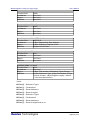
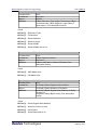
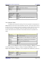
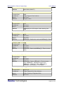
Modbus Master C# Source Code Library
Users Manual
Modbus Master C# Source Code Library
User Manual
Version 2.4
November 2008, Copyright Sunlux Technologies Ltd., All rights reserved.
Sunlux Technologies Ltd., 60-61, 1st Floor, Balaji Mansion,
Dr. Rajkumar Road., Rajajinagar, Bangalore - 560021, India
Ph: ++91 80 23322425
Fax: ++91 80 23322425
Email: [email protected]
Web: www.sunlux-india.com
Sunlux Technologies
Page 1 of 37
Modbus Master C# Source Code Library
Users Manual
Table Of Contents
1.0)
The Modbus Master Stack Source Code Library .................................................................... 3
2.0)
Important Concepts Used in SCL ............................................................................................. 5
3.0)
Pre-requisites ............................................................................................................................. 6
3.1)
Modbus Basics...................................................................................................................... 6
3.1.1)
Modbus Data types ........................................................................................................... 6
3.1.2)
Modbus Device addressing ............................................................................................... 7
3.1.3)
Modbus Data Point addressing ......................................................................................... 7
4.0)
Components of the Modbus Master SCL................................................................................. 8
5.0)
Porting the Source Code Library.............................................................................................. 9
5.1)
5.1.1)
5.2)
Physical Layer Interface Macros and Functions ................................................................. 10
OpenPort ......................................................................................................................... 10
5.2.2)
ClosePort......................................................................................................................... 12
5.2.3)
ReadPort ......................................................................................................................... 12
5.2.4)
WritePort.......................................................................................................................... 13
5.2.5)
Flush................................................................................................................................ 14
5.2.6)
OpenTCP......................................................................................................................... 15
5.2.7)
CloseTCP ........................................................................................................................ 16
5.2.8)
ReadTCP......................................................................................................................... 16
5.2.9)
WriteTCP ......................................................................................................................... 17
Stack Control Macros.......................................................................................................... 19
5.3.1)
DEBUGENABLED ........................................................................................................... 19
5.3.2)
MODBUS_TCP................................................................................................................ 19
5.3.3)
LITTLE_ENDIAN ............................................................................................................. 20
Modbus Error checking and other information..................................................................... 21
6.1)
7.0)
GetTimeInMilliseconds .................................................................................................... 10
5.2.1)
5.3)
6.0)
The User Application Interface Macros and Functions ....................................................... 10
Exception Responses ......................................................................................................... 23
Protocol Entry Functions ........................................................................................................ 24
7.1)
MBDriver_InitSerialDriver ................................................................................................... 25
7.2)
MBDriver_InitTCPDriver ..................................................................................................... 25
7.3)
MBSendRequest ................................................................................................................. 26
7.3.1)
Parameter Values for MBSendRequest .......................................................................... 28
7.3.2)
Response Format............................................................................................................ 31
7.4)
MBDriver_DeInit.................................................................................................................. 35
7.5)
MBGetLastError .................................................................................................................. 35
7.6)
MBGetLastError .................................................................................................................. 36
8.0)
Technical Specifications.......................................................................................................... 37
Sunlux Technologies
Page 2 of 37
Modbus Master C# Source Code Library
Users Manual
1.0) The Modbus Master Stack Source Code Library
Modbus® Protocol is a messaging structure developed by Modicon in 1979, used to
establish master-slave/client-server communication between intelligent devices. It is a de
facto standard, truly open and the most widely used network protocol in the industrial
manufacturing environment. Modbus is an application layer messaging protocol, positioned
at level 7 of the OSI model that provides client/server communication between devices
connected on different types of buses or networks. Modbus continues to enable millions of
automation devices to communicate. Today, support for the simple and elegant structure of
Modbus continues to grow. The Internet community can access Modbus at a reserved
system port 502 on the TCP stack. Modbus is a request/reply protocol and offers services
specified by function codes.
USER APPLICATION
MODBUS APPLICATION LAYER PROTOCOL
MODBUS TCP FRAMING
TRANSMISSION CONTROL
PROTOCOL (TCP)
MODBUS SERIAL LINE FRAMING
RS232
RS485
INTERNET PROTOCOL (IP)
ETHERNET
FO/µW...
PHYSICAL LAYER
The Modbus Master Source Code Library (SCL) is an attempt towards assisting
Original Equipment Manufacturers and HMI Software vendors in quickly implementing
Modbus support into their devices/products. The Master SCL is a C# implementation of the
Modbus Master, which the OEM integrates and ports on to the native hardware. With the
SCL the OEM can implement the Modbus stack without having any knowledge of the
Modbus standard. The implementation follows strict C# standard to enable porting of the
same on different kinds of platforms.
The figure above shows the Enhanced Protocol (Performance) Architecture (EPA)
model of the Modbus Protocol Stack. At the top of the layer is the User Application, which
Sunlux Technologies
Page 3 of 37
ETHERNET
Modbus Master C# Source Code Library
Users Manual
provides the Modbus stack with the data to be sent in Modbus frames. The Modbus
Application Layer Protocol below the top layer handles the task of assembling the required
Modbus frame based on requests. The Modbus Serial Line framing layer adds the necessary
error checking bytes to the Modbus frame before transmitting it over the physical layer. The
physical layer can be any asynchronous serial device like RS232, RS485, Fiber Optic,
microwave etc. The Modbus Serial Line implementation is the most commonly used
standard today.
Another popular implementation of Modbus is the Modbus/TCP implementation. This
implementation utilizes the popular TCP stack over Ethernet as the transport media. The
Modbus TCP Framing layer handles the additional bytes to be prefixed with the Modbus
frame before handing it over to the TCP layer, which eventually transmit the data over the
Ethernet media.
The Modbus Master SCL implements the blocks shown in gray background – the
Modbus Application Layer Protocol, the Modbus Serial Line Framing Layer and the Modbus
TCP Framing layer. The SCL provides interface Macros for the user to define using which
the user can integrate the stack with his application on one side and the physical layer on
the other. A following section describes in detail the procedure for porting the stack onto a
different platform.
Sunlux Technologies
Page 4 of 37
Modbus Master C# Source Code Library
Users Manual
2.0) Important Concepts Used in SCL
There are some important terms like Network, Session Number, Slave number etc,
which the user must know before using this SCL. The same is briefed out here for easy
reference. For example consider a “Single Master & multiple slave network” as shown in the
figure below. The Modbus slaves are connected to the Master PC through the serial
communication ports COM1, COM2 and COM3. Then we say that the Modbus Master is
connected to three serial networks. It is to be noted that ‘n’ number of networks are
numbered as 0 to ‘n-1’. Each of the networks has multiple number of slaves. In each network
the slaves are numbered as 1, 2, 3…n. Hence two slaves on different networks may have
the same slave number. The unique identifier that differentiates all the slaves (connected to
the Modbus Master) from each other is the Session number. No two slaves connected to the
Master can have the same Session number. Whenever the Modbus master communicates
with one slave, a session is formed. Hence the slaves connected to the Master altogether
are numbered as 1, 2, 3, ..n.
Sunlux Technologies
Page 5 of 37
Modbus Master C# Source Code Library
Users Manual
3.0) Pre-requisites
There are some pre-requisites before the SCL can be used in terms of
information/knowledge and/or tools/techniques. The same is explained below:
Knowledge of C# programming
The SCL has been implemented fully in C#. Porting of the SCL to a specific platform
requires the user to have C# programming knowledge since the porting activity involves
implementation of some functions skeletons.
Modbus Communication terminologies and techniques
A basic knowledge of what Modbus is used for and how the communication takes place is
useful. A brief discussion of the same is included at the end of this section.
A C# Compiler for the .NET platform in use
The platform on which the SCL is intended to be ported on must have a C# compiler since
the entire SCL must be recompiled after the user interface function implementation.
3.1) Modbus Basics
Modbus is an application layer Master-Slave protocol used for transfer of data
between two devices. The Master device always initiates a read/write request to which the
Slave device responds. The Slave device never transmits anything on its own – it must be
triggered with a request.
3.1.1) Modbus Data types
There are four different kinds of data that Modbus can transfer:
Coils – These are digital outputs. Coils can be read or written to. A possible value
for Coils is either ‘0’ or ‘1’.
Discrete Inputs – These are digital inputs. This kind of data can only be read and
cannot be written to since they represent field inputs whose value is dependent of the field
signals.
Holding Registers – Holding Register is a two-byte value (a ushort). Registers are
used for storing analog values. A Holding Register is an analog output – it can be written to
and read also.
Input Register – An input register is an analog input. Its value can be read but it
cannot be written to for the same reason as for Digital Inputs.
Sunlux Technologies
Page 6 of 37
Modbus Master C# Source Code Library
Users Manual
3.1.2) Modbus Device addressing
Modbus is a multipoint protocol. This means that one master can communicate with
multiple slaves on the same communication line. Due to this a given slave must have a
unique ID with which to address it – a Modbus device address. A slave’s device address
MUST be unique on a given communication network – duplicate addresses lead to bus
collision. Modbus device addresses must lie in the range 1 to 247. The Modbus Master
Source Code Library supports broadcast addressing also. For broadcasting a message the
device address must be specified as 0 (zero). All the slaves on the specified network will
receive the same request. It should be noted that broadcasting is not possible for all the
requests. The list of commands for which broadcasting is supported is given under section
'Technical Specifications'. The Modbus Master Source Code Library can also handle
exception responses received from the slave and will produce appropriate error messages.
The same is explained in detail in section 'Exception Responses'.
3.1.3) Modbus Data Point addressing
Modbus uses unique addresses to refer to data points. Each of the four data types has
independent addresses starting from 0001 to FFFF. This means that there can be a Coil
located at 0001 and a Digital Input also at address 0001. However a slave device need not
necessarily have data points at all the addresses. The data points need not be at
consecutive locations.
Sunlux Technologies
Page 7 of 37
Modbus Master C# Source Code Library
Users Manual
4.0) Components of the Modbus Master SCL
The Modbus Master SCL is implemented using the following files:
ModBusMaster.cs -- This file contains the implementation of the Modbus Master
Stack as well as the class that implements the interface functions.The stack is implemented
in the class CMBMasterStack, which contains the functions used to initialize various data
structures, functions to construct modbus data structures and to send and receive modbus
frame, functions for constructing & parsing the modbus frames. This class also contains the
error handling code. The end user should not make modifications to this class. This file also
contains the class CUserData which contains all the user interface functions that must be
implemented by the end user. The user should modify only the functions under the
CUserData class.
MasterMain.cs -- This file contains demonstration code to show how the C# Modbus
classes are to be used in an application. The user may modify the code as per his
requirements.
SerialComm.cs --Microsoft has not supplied any class that encapsulates serial
RS232 communication with C#. In order to facilitate faster development for the end users, a
serial communication class called CserialComm is bundled with the C# SCL.
TcpComm.cs -- This file contains the implementation of the TCP communication
path class.
Sunlux Technologies
Page 8 of 37
Modbus Master C# Source Code Library
Users Manual
5.0) Porting the Source Code Library
Since the SCL has been written using C# it is possible to adapt it to different types of
physical interfaces as well as interface it into an users application. The implementation is
independent of physical transmission layer giving the user full freedom to choose the media.
Based on the physical layer chosen, the physical layer functions of the CUserData class
must be implemented by the user. Similarly the user interface of the driver (i.e. the manner in
which the SCL interacts with the user application and database) is also left open – the user
can implement it in any manner desired by him. So the porting of the SCL involves
implementing the interface functions.
The porting of the SCL to a native platform is done in three steps as below:
Implement the User Application Interface Functions of the CUserData class
•
GetTimeInMilliseconds
Define and implement the Physical Layer Interface Functions
•
OpenPort
•
ClosePort
•
ReadPort
•
WritePort
•
Flush
•
OpenTCP
•
CloseTCP
•
ReadTCP
•
WriteTCP
Define the Stack Control Macros
•
DEBUGENABLED
•
MODBUS_TCP
•
LITTLE_ENDIAN
Sunlux Technologies
Page 9 of 37
Modbus Master C# Source Code Library
Users Manual
5.1) The User Application Interface Macros and Functions
The SCL implementation of the stack requires some information, which is user
specific for it’s functioning. To enable the SCL obtain this information several User
Application Interface functions have been defined, which the end user is expected to
implement. The stack calls these functions to obtain some user specific data from the user
application and also allow interaction between the stack and the user application. The
following functions are provided for the user to interface his application and database with
the stack:
5.1.1) GetTimeInMilliseconds
Format: uint GetTimeInMilliseconds()
This function is called by the stack to determine the system time in milliseconds. The
implementation of this function should return the system time in milliseconds. The stack uses
this function for time-out processing. The stack gets the system time just before transmitting
the request to the slave and then makes multiple successive calls to this function till the
response from the slave is obtained. On every call to this function the stack compares the
time at transmission and the presently obtained time. If the slave does not respond within
the specified Timeout period, the stack generates the ‘Timeout’ error.
Expected return value: uint, System time in Milliseconds.
Parameters: None
A sample implementation is as below:
// ModBusMaster.cs file – returns the system time in milliseconds
uint GetTimeInMilliseconds() { return (uint)GetTickCount(); }
5.2) Physical Layer Interface Macros and Functions
The implementation of the SCL stops at the point of framing and parsing the Modbus
data – the functionality of transmitting and receiving the frames to/from the physical layer is
kept open to enable portability of the SCL to different platforms and also to different physical
layers. These functions allow the stack to use the Physical Layer chosen by the user to
transmit and receive Modbus frames. The following functions are available:
5.2.1) OpenPort
Format: bool OpenPort(string PortName,
int BaudRate,
int Parity,
Byte StopBits)
Sunlux Technologies
Page 10 of 37
Modbus Master C# Source Code Library
Users Manual
This function is called by the stack during the application startup to initialize its
communication path. This function is expected to return a path ID or handle to the
communication path on which further Modbus communication is to happen. The path
ID/handle will have different forms in different operating systems/platforms. For e.g. on a
UNIX platform a serial communication path identifier is a simple two byte value representing
the path. On Windows it is a double word Handle to the serial communication port. The form
is different for a TCI/IP Socket connection. So based on the desired physical interface and
the port this function must return a unique communication path identifier, which will be used
for all further communications. The option of setting up the communication path by initializing
it with various parameters should be done in this function itself. A sample implementation
can be as below:
Expected Return Value: bool true – If initialisation/open successful
false – If Initialization/open fails
Parameters: These parameters are the same, which are supplied by the user application
through the function ‘MBDriver_Init ()’ .
string PortName
int BaudRate
int Parity
byte StopBits
A sample implementation is as below:
// SerialComm.cs file – a Windows implementation for a serial
// communication port
bool OpenPort(string PortName, int BaudRate, int Parity, Byte StopBits)
{
DCB dcb = new DCB();
COMMTIMEOUTS TimeOut;
hCom = CreateFile(PortName,
GENERIC_READ | GENERIC_WRITE,
0, /* comm devs must be opened w/exclusive-access */
IntPtr.Zero,
/* no security attrs */
OPEN_EXISTING, /* comm devs must use OPEN_EXISTING */
0,
/* not overlapped I/O */
IntPtr.Zero); /* must be NULL for comm devices */
if(hCom.Equals(INVALID_HANDLE_VALUE)) { return false; }
fSuccess = GetCommState(hCom, ref dcb);
if(!fSuccess) { return false; }
dcb.BaudRate
dcb.ByteSize
dcb.StopBits
dcb.Parity
=
=
=
=
BaudRate;
8;
StopBits;
(byte)Parity;
Sunlux Technologies
Page 11 of 37
Modbus Master C# Source Code Library
Users Manual
fSuccess = SetCommState(hCom, ref dcb);
if(!fSuccess) {return false;}
fSuccess = GetCommTimeouts(hCom, out TimeOut);
if(!fSuccess) { return false; }
TimeOut.ReadTotalTimeoutConstant = 0;
TimeOut.ReadTotalTimeoutMultiplier = 0;
TimeOut.ReadIntervalTimeout = MAXDWORD;
fSuccess = SetCommTimeouts(hCom, ref TimeOut);
if(!fSuccess) { return false; }
return true;
}
5.2.2) ClosePort
Format: byte ClosePort()
The stack calls this function just before it exits, to close and free the communication
path/port used by the stack for Modbus communication. This allows other applications to use
the communication path after the Modbus stack/user application exits. The implementation
must de-initialise the communication path if required and then close it.
Expected Return Value: byte - TRUE if successful, FALSE otherwise
Here TRUE=1 & FALSE=0
Parameters: None
A sample implementation is as below:
//SerialComm.cs file
byte ClosePort()
{
fSuccess = CloseHandle(hCom);
if(!fSuccess) { return FALSE;}
return TRUE;
}
5.2.3) ReadPort
Format: byte ReadPort(byte[] Buffer,
int NumberOfBytesToRead,
ref int NumberOfBytesRead)
The stack calls this function to read the characters/bytes from the communication
path. This function must be implemented for the stack to function properly. The
implementation of this function must read the requested number of bytes from the specified
communication path and copy the same into the pre-allocated buffer which is passed as a
parameter. The function should also copy the number of bytes of data read into a reference
Sunlux Technologies
Page 12 of 37
Modbus Master C# Source Code Library
Users Manual
variable which is passed as a parameter. If an error is encountered in the reading process
(for e.g. due to network fault), the function should return FALSE (zero value) indicating
failure. Otherwise even if the number of bytes read is zero (for e.g. when there are no bytes
available at the network/port) the function should return TRUE (i.e. value 1).
Expected Return Value: byte - TRUE if No error occurs during reading
FALSE otherwise
Here TRUE=1 & FALSE=0
Parameters:
byte[] Buffer – A pre-allocated buffer to store received bytes.
int NumberOfBytesToRead – Num of bytes to read from port.
ref int NumberOfBytesRead – Reference to int variable to hold the number of bytes read
from the port.
A sample implementation is as below:
// SerialComm.cs file – implementation for a serial
// communication port with no timeout processing
byte ReadPort(byte[] Buffer,
int NumberOfBytesToRead,
ref int NumberOfBytesRead)
{
int LocBytesRead = 0;
fSuccess = ReadFile(hCom,
Buffer,
NumberOfBytesToRead,
out LocBytesRead,
ptrUWO);
if(!fSuccess)
{
NumberOfBytesRead = LocBytesRead;
return FALSE;
}
NumberOfBytesRead = LocBytesRead;
return TRUE;
}
5.2.4) WritePort
Format: byte WritePort(byte[] Buffer,
int NumberOfBytesToWrite,
ref int BytesWrote)
The stack calls this function to write the Modbus reply to the communication path.
This function must be implemented for the stack to function properly. The implementation of
this function must write the requested number of bytes from the buffer (passed as a
parameter) to the specified communication path and should also put the number of bytes of
data actually written into a reference variable (passed as a parameter). If an error is
Sunlux Technologies
Page 13 of 37
Modbus Master C# Source Code Library
Users Manual
encountered in the writing process(for e.g. due to network fault), the function should return
FALSE (zero value) indicating failure. Otherwise the function should return TRUE (i.e. value
1).
Expected Return Value: byte - TRUE if No error occurs during Writing
FALSE otherwise
Here TRUE=1 & FALSE=0
Parameters:
byte[] Buffer – A pre-allocated buffer containing the data to be written to the port.
int NumberOfBytesToWrite – Number of bytes to be written to the port.
ref int BytesWrote – Reference to int variable to hold the number of bytes written to the port.
A sample implementation is as below:
// SerialComm.cs file – implementation for a serial
// communication port
byte WritePort( byte[] Buffer,
int NumberOfBytesToWrite,
ref int BytesWrote)
{
Int32 NumberOfBytesWritten = 0;
fSuccess = WriteFile( hCom,
Buffer,
NumberOfBytesToWrite,
out NumberOfBytesWritten,
ptrUWO);
if(!fSuccess)
{
BytesWrote = NumberOfBytesWritten;
return FALSE;
}
BytesWrote = NumberOfBytesWritten;
return TRUE;
}
5.2.5) Flush
Format: void Flush()
The stack calls this function to clear the communication buffer (i.e. delete residual
bytes) whenever it encounters an error in reading the Modbus frame so that it can start a
fresh with the next Modbus frame. The implementation of this function must clear all data of
the communication path.
Expected Return Value: None
Parameters: None
Sunlux Technologies
Page 14 of 37
Modbus Master C# Source Code Library
Users Manual
A sample implementation is as below:
// SerialComm.cs file – a Windows implementation for a serial
// communication port
int retval;
void Flush()
{
int retval;
retval = PurgeComm(hCom,PURGE_TXCLEAR | PURGE_RXCLEAR);
}
5.2.6) OpenTCP
Format: bool OpenTCP(String SlaveIPAddr, int IPPortNo)
This function is called by the stack during the application startup to initialize its
communication path. This function is expected to return a path ID or handle to the
communication path on which further Modbus communication is to happen. The path
ID/handle will have different forms in different operating systems/platforms. For e.g. on a
UNIX platform a serial communication path identifier is a simple two byte value representing
the path. On Windows it is a double word Handle to the serial communication port. The form
is different for a TCI/IP Socket connection. So based on the desired physical interface and
the port this function must return a unique communication path identifier, which will be used
for all further communications. The option of setting up the communication path by initializing
it with various parameters should be done in this function itself.
Expected Return Value: bool true – If initialisation/open successful
false – If Initialization/open fails
Parameters: These parameters are the same, which are supplied by the user application
through the function ‘MBDriver_Init ()’ .
string SlaveIPAddr
int IPPortNo
A sample implementation is as below:
// TcpComm.cs file – implementation for a TCP/IP communication.
bool OpenTCP(String SlaveIPAddr,int IPPortNo)
{
MBSock = new Socket ( AddressFamily.InterNetwork,
SocketType.Stream,
ProtocolType.Tcp );
IPAddress IPAdd = IPAddress.Parse (SlaveIPAddr);
int IPortNo = System.Convert.ToInt16 (IPPortNo);
Sunlux Technologies
Page 15 of 37
Modbus Master C# Source Code Library
Users Manual
IPEndPoint ipEnd = new IPEndPoint (IPAdd,IPortNo);
MBSock.Connect ( ipEnd );
if(MBSock.Connected) {return true;}
else {return false;}
}
5.2.7) CloseTCP
Format: byte CloseTCP( )
The stack calls this function just before it exits, to close and free the communication
path/port used by the stack for Modbus communication. This allows other applications to use
the communication path after the Modbus stack/user application exits. The implementation
must de-initialise the communication path if required and then close it.
Expected Return Value: byte
– TRUE(1) if successful.
– FALSE(0) if not successful.
Parameters: None
A sample implementation is as below:
// TcpComm.cs file –
// communication.
byte CloseTCP()
{
MBSock.Close();
return TRUE;
implementation for a TCP/IP
}
5.2.8) ReadTCP
Format: byte ReadTCP(byte[] buffer,
int NumberOfBytesToRead,
ref int NumberOfBytesRead)
The stack calls this function to read the characters/bytes from the communication
path. This function must be implemented for the stack to function properly. The
implementation of this function must read the requested number of bytes from the specified
communication path and copy the same into the pre-allocated buffer which is passed as a
parameter. The function should also copy the number of bytes of data read into a reference
variable which is passed as a parameter. If an error is encountered in the reading process
(for e.g. due to network fault), the function should return FALSE (zero value) indicating
failure. Otherwise even if the number of bytes read is zero (for e.g. when there are no bytes
available at the network/port) the function should return TRUE (i.e. value 1).
Sunlux Technologies
Page 16 of 37
Modbus Master C# Source Code Library
Users Manual
Expected Return Value: byte - TRUE if No error occurs during reading
FALSE otherwise
Here TRUE=1 & FALSE=0
Parameters:
byte[] Buffer – To hold the data read from the port.
int NumberOfBytesToRead – Number of bytes to read from the port.
ref int NumberOfBytesRead – Reference to int variable to hold the numebr of bytes read
from the port.
A sample implementation is as below:
// TcpComm.cs file – implementation for a TCP/IP
// communication.
byte ReadTCP( byte[] buffer,
int NumberOfBytesToRead,
ref int NumberOfBytesRead)
{
try{
NumberOfBytesRead =
MBSock.Receive(
buffer,
NumberOfBytesToRead,
0);
}
catch(SocketException e){ return FALSE; }
return TRUE;
}
5.2.9) WriteTCP
Format: byte WriteTCP(byte[] byData,
int NumberOfBytesToWrite,
ref int NumberOfBytesWritten)
The stack calls this function to write the Modbus reply to the communication path.
This function must be implemented for the stack to function properly. The implementation of
this function must write the requested number of bytes from the buffer (passed as a
parameter) to the specified communication path and should also put the number of bytes of
data actually written into a reference variable (passed as a parameter). If an error is
encountered in the writing process(for e.g. due to network fault), the function should return
FALSE (zero value) indicating failure. Otherwise the function should return TRUE (i.e. value
1).
Expected Return Value: byte - TRUE if No error occurs during reading
FALSE otherwise
Here TRUE=1 & FALSE=0
Parameters:
Sunlux Technologies
Page 17 of 37
Modbus Master C# Source Code Library
Users Manual
byte[] byData – To hold the data that is to be written to the port.
int NumberOfBytesToWrite – Number of bytes written to the port.
ref int NumberOfBytesWritten – Reference to the variable to hold the Number of bytes
written to the port.
A sample implementation is as below:
// TcpComm.cs file – implementation for a TCP/IP
// communication.
byte WriteTCP( byte[] byData,
int NumberOfBytesToWrite,
ref int NumberOfBytesWritten)
{
try
{
NumberOfBytesWritten =
MBSock.Send(byData);
return TRUE;
}
catch(SocketException e)
{
Console.Write("SocketException: {0}", e);
return FALSE;
}
}
Sunlux Technologies
Page 18 of 37
Modbus Master C# Source Code Library
Users Manual
5.3) Stack Control Macros
The Stack Control Macros control the behavior of the stack by changing the control
flow by means of pre-processor directives. By setting appropriate values for these macros
the user can control the compilation process. The following macros are provided:
5.3.1) DEBUGENABLED
For ease of debugging the SCL uses several “Console.Write” and
“Console.WriteLine” statements internally. However since these debugging statements
consume considerable amount of code memory and also take up a lot of execution time, the
DEBUGENABLED macro has been provided using which the user can enable or disable
printing of debugging statements. To enable debugging define the above symbol – else
undefine it.
Example:
// ModBusMaster.cs, SerialComm.cs, TcpComm.cs files – Enables the
// “Console.Write” and “Console.WriteLine” statements in the stack.
#define DEBUGENABLED
// ModBusMaster.cs, SerialComm.cs, TcpComm.cs files – Disables the
// “Console.Write” and “Console.WriteLine” statements in the stack.
#undef DEBUGENABLED
5.3.2) MODBUS_TCP
This symbol must be defined if the Modbus stack is being used for communication
over TCP. The framing methodology followed for a serial line Modbus communication and
Modbus TCP communication is different. The Modbus/TCP specifications are different from
the Serial standard mainly in two ways
Serial uses a two byte CRC at the end of the frame whereas Modbus/TCP does not
(since error checking and correction are handled in other layers of TCP itself)
Modbus/TCP uses an additional 6 byte header before the slave address field of a
frame.
Example:
// ModBusMaster.cs, SerialComm.cs, TcpComm.cs MasterMain.cs files –
// Chooses the communication to take place over TCP/IP
#define MODBUS_TCP
// ModBusMaster.cs, SerialComm.cs, TcpComm.cs MasterMain.cs files –
// Chooses the communication to take place over Serial
#undef MODBUS_TCP
Sunlux Technologies
Page 19 of 37
Modbus Master C# Source Code Library
Users Manual
5.3.3) LITTLE_ENDIAN
If the hardware architecture chosen follows the LITTLE_ENDIAN style of storing
ushorts, then this symbol must be defined. Depending on the operating system and the
hardware platform, there are two ways of storing a ushort variable in memory. In the first
case called the BIG ENDIAN style the high byte of the ushort is stored first and then the low
byte of the ushort. This style can generally be found in MOTOROLA based CPU
architectures. In the other style called the LITTLE ENDIAN, the low byte of the ushort is
stored first and then the high byte of the ushort. This style is more prominent in CPU’s
following the INTEL architecture. Modbus follows the BIG ENDIAN style of packing ushorts
in its frames. So on platforms supporting LITTLE ENDIAN style the two bytes forming the
ushort must be reversed if the data is to be copied properly. This is internally done in the
stack if the LITTLE_ENDIAN symbol is defined.
Example:
// ModBusMaster.cs file
// Selects the system on which the stack is running as Little Endian
#define LITTLE_ENDIAN
// ModBusMaster.cs file
//Selects the system on which the stack is running as Big Endian
#undef LITTLE_ENDIAN
NOTE : If the hardware architecture chosen follows the LITTLE ENDIAN style then
this macro should be defined, shown above. If it follows BIG ENDIAN style then this macro
should be undefined.
Sunlux Technologies
Page 20 of 37
Modbus Master C# Source Code Library
Users Manual
6.0) Modbus Error checking and other information
The Modbus Library stores information about the errors it encounters in executing
Modbus requests. The user application can read this error information using method
“MBGetLastError” to check which error occurred during the last Modbus request handling.
This method has the following structure:
MbErrorCodes MBGetLastError ()
The possible error codes are defined under enumeration type MbErrorCodes.
MbErrorCodes
Enum
NoError
NotEnoughMemory
UnknownServiceRequ…
InvalidRegisterAddress
ExceedsMaxItems
TimeOutOccured
BadCRC
SlaveIdMismatch
NetworkWriteError
NetworkReadError
InvalidSlaveId
TransactionIdMismatch
BadSequence
Defines a set of error codes that can be returned by the class library. The last
occurred error in the library can be retrieved by calling MbGetLastError.
Enumerator:
•
NoError : The last requested Modbus service completed successfully.
•
NotEnoughMemory : Insufficient memory to complete requested service.
•
UnknownServiceRequest : Requested Modbus service is not known to this
library.
•
InvalidRegisterAddress : Specified register address is invalid. This error
code is present for backward compatibility only and is no longer used.
•
ExceedsMaxItems : The no. of Modbus items specified in the request
exceeds the maximum supported. The limit for the number of items specified
depends on the requested Modbus service.
Sunlux Technologies
Page 21 of 37
Modbus Master C# Source Code Library
•
Users Manual
TimeOutOccured : Timeout occured waiting for response from the Modbus
slave.
•
BadCRC : Received Modbus response message had a bad CRC.
•
SlaveIdMismatch : Slave ID field in the received response message did not
match the one in the request message.
•
NetworkWriteError : Could not write to the selected communication port.
•
NetworkReadError : Could not read from the selected communication port.
•
InvalidSlaveId : Slave ID specified is invalid for the requested service. Valid
slave numbers are : for read functions 1 to 247 and for write functions 0 to
247, where 0 is for broadcasting.
•
TransactionIdMismatch : The transaction ID field in the received response
message does not match the one in the request message.
•
BadSequence : Bad method call sequence (for e.g. calling MBSendRequest
before InitCommPath).
If this method returns MbErrorCodes.ExceptionResponse, then MBGetLastExceptionCode
must be called to get the exception code of the exception response.
Sunlux Technologies
Page 22 of 37
Modbus Master C# Source Code Library
Users Manual
6.1) Exception Responses
Exception Responses are those sent by the slave for a master request when it is
unable to perform the requested task. The Master library is designed and implemented to
receive such exception responses and store the exception response code in the member
variable ‘mbLastException’. User should note that no action is taken within the stack on
receiving the exception responses except for Exception Code 5. The users application
should take appropriate actions depending on the exception response.
Some Modbus slaves do not support exception responses. Such devices usually do
not send any response under such “exception” conditions in which case the master will
experience a time out.
The last occurred exception code can be retrieved by a call to the function
‘MBGetLastExceptionCode’.
byte MBGetLastExceptionCode()
The list of exception responses supported is as below:
Excp.
Constant Variables
Code
1
ILLEGALFUNCTION
2
3
4
5
6
7
8
Description
Illegal Function. The slave does not support the
requested function
ILLEGALDATAADDRESS
Illegal data address. The data address received in
the query is not a supported address in the slave.
This response is sent by a slave when a master
makes read/write request on a non-existent
variable address.
ILLEGALDATAVALUE
Illegal data value. A value contained in the query
data field is not an allowable value for the slave.
The slave sends this response when it receives a
write request from the master with a “value” which
is considered illegal for the variable.
SLAVEDEVICEFAILURE
Slave device failure. An unrecoverable error
occurred while the slave was attempting to perform
the requested action.
ACKNOWLEDGE
Acknowledge. The slave has accepted the request
and is processing it. But a long duration of time will
be required to do so. This response is returned to
prevent a time out error from occurring in the
master.
SLAVEDEVICEBUSY
Slave device busy. The slave is engaged in
processing a long–duration program command.
The master should retransmit the message later
when the slave is free.
NEGATIVEACKNOWLEDGE Negative Acknowledge. The slave cannot perform
the program function received in the query.
MEMORYPARITYERROR
Memory Parity Error. The slave attempted to read
extended memory, but detected a parity error in
the memory. The master can retry the request, but
service may be required on the slave device.
Sunlux Technologies
Page 23 of 37
Modbus Master C# Source Code Library
Users Manual
7.0) Protocol Entry Functions
The end user needs to call only the protocol entry functions in his application
program to avail the functionality of the protocol. There are three entry functions which the
user can make use of. The Modbus driver must be initialized by calling ‘MBDriver_Init’
function before calling any other function. Once initialized the user can make use of
‘MBSendRequest’ for Modbus transactions. This function constructs the Modbus frame,
sends it to the specified slave, receives the response, parses it and returns the received
data to the user. Using this function ‘MBSendRequest’ the user can send the commands
described in the section below. At the end of the Modbus transactions ‘MBDriver_DeInit’
function should be called. An example of such a call is as given below:
void main(void)
{
int i, Index=0;
byte SessionNo=1;
ushort VarAddress=0x0001;
ushort NItems=3;
byte Retries=1, FunctionCode=3;
byte retvalbool;
uint TimeOut = 2000, OldTime, NewTime;
string PortName = "COM2";
int BaudRate = 9600;
int Parity = 0;
byte StopBits = 2;
ushort[] Coildata = new ushort[255];
// Create and instantiate Modbus Master driver
CMBMasterStack MBMasterStack = new CMBMasterStack();
/* Initialize the Modbus serial driver */
Retvalbool = MBMasterStack.MBDriver_InitSerialDriver( PortName,
BaudRate,
Parity,
StopBits);
if(retvalbool==0) {
Console.WriteLine("\nModbus Driver Initialisation failed");
return;
}
/* Send and Receive the Modbus Request and Response */
retvalbool = MBMasterStack.MBSendRequest( SessionNo,
FunctionCode,
VarAddress, NItems,
Coildata, TimeOut,
Retries );
if(retvalbool==1){
Console.Write("\nModbus request success\n"); }
Successful */
else{
Sunlux Technologies
/* if
Page 24 of 37
Modbus Master C# Source Code Library
Users Manual
MBErrNo = MBMasterStack.MBGetLastError();
Console.WriteLine("Modbus request failure, ErrNum = {0}",
MBErrNo); /* if Error occurred */
}
/* Deintialize the Modbus serial driver after transaction */
MBMasterStack. MBDriver_DeInit();
} /*end of main*/
The prototypes of the entry functions and the files in which these functions are
defined are as follows.
7.1) MBDriver_InitSerialDriver
Format: byte MBDriver_InitSerialDriver( string PortName,
int BaudRate,
int Parity,
byte StopBits )
This function initializes the specified communication path with the specified
parameters and it also initializes some data structures required by the stack. This function
should be called before calling any other functions. This function is relevant only for
asynchronous serial communication ports. The parameters are as explained below:
Parameters:
Sl. No. Parameter Name Description
1
PortName
Network or Port over which to open
the Modbus communication.
2
BaudRate
Baud Rate for data transfer
3
Parity
Parity checking type for data
transfer
5
StopBits
Stop Bits for data transfer
Data Type
string
int
int
byte
Return Value: byte - MBDEFS_TRUE: If initialisation successful
MBDEFS_FALSE: If initialisation fails
Here MBDEFS_TRUE = 1 and MBDEFS_FALSE = 0
7.2) MBDriver_InitTCPDriver
Format: byte MBDriver_InitTCPDriver(String SlaveIPAddr,int IPPortNo)
This function is the Modbus TCP equivalent of MBDriver_InitSerialDriver and is
relevant only to TCP communication ports.
Parameters:
Sunlux Technologies
Page 25 of 37
Modbus Master C# Source Code Library
Users Manual
Sl. No. Parameter Name Description
1
SlaveIPAddr
Network over which to open the
Modbus communication
2
IPPortNo
IP Port Number
Data Type
string
int
Return Value: byte - MBDEFS_TRUE: If initialisation successful
MBDEFS_FALSE: If initialisation fails
Here MBDEFS_TRUE = 1 and MBDEFS_FALSE = 0
7.3) MBSendRequest
Format: byte MBSendRequest(
byte SlaveNo, byte FunctionCode,
ushort VarAddress, ushort NItems,
ushort[] data, uint TimeOut,
byte Retries )
This function is used to send the request and receive the response from the Modbus
slave.
Parameters:
Sl. Parameter
No. Name
1
SlaveNo
Description
Slave ID from which data is to
be read
Data
Type
byte
2
FunctionCode Type of data to be requested
from the slave
byte
3
VarAddress
Starting variable address of the ushort
data to be read
4
NItems
No of items of the specified type ushort
to be read
5
data
Memory allocated data buffer for ushort
receiving the requested data
6
TimeOut
Time out in milliseconds for the
Read operation
uint
7
Retries
No of retries in case of
transmission failure
byte
Values
1 - 247
Supported list
given in Technical
Specification
section.
1 – 65535
**Number of Coils
/ DiscreteInputs / Registers.
Valid data buffer
with memory
allocated for
receiving ‘Items’
As decided by the
end user.
As decided by the
end user.
Return Value: byte - MBDEFS_TRUE: If initialisation successful
MBDEFS_FALSE: If initialisation fails
Here MBDEFS_TRUE = 1 and MBDEFS_FALSE = 0
Sunlux Technologies
Page 26 of 37
Modbus Master C# Source Code Library
Users Manual
Return value of ‘MBDEFS_FALSE’ indicates an error. In case of an error refer to the
error code in the member variable ‘MBErrNo’.
**For Serial communication:
Number of coils/Discrete inputs: 1 to 2008
Number of Registers: 1 to 125
For Modbus TCP communication:
Number of coils/Discrete inputs: 1 to 1976
Number of Registers: 1 to 123
This is as per Modbus Standard Specifications
Sunlux Technologies
Page 27 of 37
Modbus Master C# Source Code Library
Users Manual
7.3.1) Parameter Values for MBSendRequest
The tables below indicate the possible values to be passed as parameters to the
MBSendRequest function for different function codes. The tables are provided for better
understanding of the usage of the above function. The columns on the left indicate the
parameters and the ones on the left describe the value to be entered for the same. The
SlaveAdd, TimeOut and Retries fields are the same for all function codes and are hence
described in the first table below and not repeated in the others.
Function Code - FC 0x01/ FC 0x02/ FC 0x03/ FC 0x04
SlaveAdd
1 byte Modbus Slave Address to communicate with
FunctionCode
0x01/0x02/0x03/0x04
VarAddress
Nitems
*MBData
TimeOut
Retries
2 Byte Register/Coil Start Address
2 Byte Quantity of Registers/Coils
Not used
Time Out period to wait for response in milliseconds
No. of Retries to perform before aborting transaction
Function Code - FC 0x05
FunctionCode
0x05
VarAddress
2 Byte Coil Start Address
Nitems
Not Used
*MBData
0001/0000 (ON/OFF)
Function Code - FC 0x06
FunctionCode
0x06
VarAddress
2 Byte Register Start Address
Nitems
Not Used
*MBData
Register Value
Function Code - FC 0x07
FunctionCode
0x07
VarAddress
Not Used
Nitems
Not Used
*MBData
Not Used
Function Code - FC 0x08
FunctionCode
0x08
VarAddress
Not Used
Nitems
Not Used
*MBData
MBData[0] - Subfunction code and MBdata[1] - Data
Sunlux Technologies
Page 28 of 37
Modbus Master C# Source Code Library
Users Manual
Function Code - FC 0x0B
FunctionCode
0x0B
VarAddress
Not Used
Nitems
Not Used
*MBData
Not Used
Function Code - FC 0x0C
FunctionCode
0x0C
VarAddress
Not Used
Nitems
Not Used
*MBData
Not Used
Function Code - FC 0x0F/FC 0x10
FunctionCode
0x0F/0x10
VarAddress
2 Byte Register/Coil Start Address
Nitems
2 Byte Quantity of Registers/Coils
*MBData
Registers/Coils Data
Function Code - FC 0x11
FunctionCode
0x11
VarAddress
Not Used
Nitems
Not Used
*MBData
Not Used
Function Code - FC 0x14
FunctionCode
0x14
VarAddress
Not Used
Nitems
2 Byte Total number of Reference Types Groups.
*MBData
(1 Byte Reference Type, 2 Byte File Number, 2 Byte
Record Number, 2 Byte Register Length) * Nitems.
(**See description below)
**Note:
MBData[0] – Reference Type1
MBData[1] – File Number1
MBData[2] – Record Number1
MBData[3] – Record Length1
MBData[4] – Reference Type2
MBData[5] – File Number2
MBData[6] – Record Number2
MBData[7] – Record Length2 and so on.
Sunlux Technologies
Page 29 of 37
Modbus Master C# Source Code Library
Users Manual
Function Code - FC 0x15
FunctionCode
0x15
VarAddress
Not Used
Nitems
0x0001
*MBData
1 Byte Reference Type,2 Byte File Number,2 Byte
Record Number,2 Byte Register Length,Data (2
Bytes each).(**See description below)
**Note:
MBData[0] – Reference Type
MBData[1] – File Number
MBData[2] – Record Number
MBData[3] – Record Length
MBData[4] – Record Data1
MBData[5] – Record Data2 and so on
Function Code - FC 0x16
FunctionCode
0x16
VarAddress
2 Byte Register Address
Nitems
Not Used
*MBData
2 Bytes AND Mask, 2 Bytes OR Mask(**See
description below)
**Note
MBData[0] – AND Mask value
MBData[1] – OR Mask value
Function Code - FC 0x17
FunctionCode
0x17
VarAddress
[to Read] 2 Bytes Register Start Address
Nitems
[to Read] 2 Bytes Quantity of Registers
*MBData
[to Write] 2 Bytes Register Start Address, 2 Bytes
Quantity of
Registers, Data(2 Bytes each)(**See description
below)
**Note
MBData[0] – Write Register Start address
MBData[1] – Number of Items to write
MBData[2] – Write Data1
MBData[3] – Write Data2 and so on.
Sunlux Technologies
Page 30 of 37
Modbus Master C# Source Code Library
Users Manual
Function Code - FC 0x18
FunctionCode
0x18
VarAddress
2 Byte FIFO Pointer Address
Nitems
Not Used
*MBData
Not Used
Function Code - FC 0x2B
FunctionCode
0x2B
VarAddress
Not Used
Nitems
N Bytes
*MBData
1 Byte MEI Type, MEI Type Specific Data((N-1)
Bytes)
7.3.2) Response Format
The tables below indicate the meaning of the values contained in the parameters of
MBSendRequest function after it has completed its execution. This function copies some of
the data received in the response frames into parameteric variables which the user can use
for further processing. The SlaveAdd, TimeOut and Retries fields are the same for all
function codes and are hence described in the first table below and not repeated in the
others.
Function Code - FC 0x01/ FC 0x02/ FC 0x03/ FC 0x04
SlaveAdd
Slave Address as contained in the response frame
FunctionCode
0x01/0x02/0x03/0x04
VarAddress
2 Byte Register/Coil Start Address in the response
frame
Nitems
2 Byte Quantity of Registers/Coils in the response
frame
*MBData
Status / Value of Registers/Coils
TimeOut
Time Out
Retries
Retries
Note: For Coils, MBData[0] = Status of Coil With VarAddress, MBData[1] = Status of
Coil With (VarAddress+1) and so on. Similarly For Registers, MBData[0] = Value of
Register With VarAddress, MBData[1] = Value of Register With (VarAddress+1) and so on.
Function Code - FC 0x05
FunctionCode
0x05
VarAddress
2 Byte Coil Start Address
Nitems
Not Used
Sunlux Technologies
Page 31 of 37
Modbus Master C# Source Code Library
Users Manual
Function Code - FC 0x05
*MBData
0001/0000 (ON/OFF)
Function Code - FC 0x06
FunctionCode
0x06
VarAddress
2 Byte Register Start Address
Nitems
Not Used
*MBData
Register Value
Function Code - FC 0x07
FunctionCode
0x07
VarAddress
Not Used
Nitems
Not Used
*MBData
MBData[0] have 8 Exception status starting from
LSB.
Function Code - FC 0x08
FunctionCode
0x08
VarAddress
Not Used
Nitems
Not Used
*MBData
MBData[0] - Subfunction code and MBData[1] - Data
Function Code - FC 0x0B
FunctionCode
0x0B
VarAddress
Not Used
Nitems
Not Used
*MBData
MBData[0] - Status and MBData[1] – Event counter
value
Function Code - FC 0x0C
FunctionCode
0x0C
VarAddress
Not Used
Nitems
Not Used
*MBData
MBData[0] – Status, MBData[1] – Event counter
value, MBData[2] – Message counter value ,
MBData[3] – Total Events and MBData[4] to
MBData[4 + MBData[3] ] – Event Bytes.
Function Code - FC 0x0F/FC 0x10
FunctionCode
0x0F/0x10
VarAddress
2 Byte Register/Coil Start Address
Nitems
2 Byte Quantity of Registers/Coils
*MBData
Not Used
Sunlux Technologies
Page 32 of 37
Modbus Master C# Source Code Library
Users Manual
Function Code - FC 0x11
FunctionCode
0x11
VarAddress
Not Used
Nitems
Not Used
*MBData
**See the description below.
**Note:
MSB of MBData[0] – Total Bytes of valid data in the buffer MBData,
LSB of MBData[0] – Slave Id,
MSB of MBData[1] – Total Bytes of valid data in the buffer MBData,
LSB of MBData[1] – Slave Id,
MSB of MBData[2] – Run Indicator Status,
LSB of MBData[2] – Device Specific Data Byte[0],
MSB of MBData[3] – Device Specific Data Byte[1],
LSB of MBData[3] – Device Specific Data Byte[2] and so on.
IMPORTANT: Data stored in this buffer as bytes(unsigned char type) and not as two
bytes(unsigned short type).
Function Code - FC 0x14
FunctionCode
0x14
VarAddress
Not Used
Nitems
2 Byte Total number of Reference Types Groups.
*MBData
(1 Byte Reference Type, 2 Byte File Number, 2 Byte
Record Number, 2 Byte Register Length) *
Nitems.(**See description below)
**Note:
MBData[0]
– File Response Length1,assume MBData[0]= n.
MBData[1]
– Reference Type1
MBData[2]
– Record Data 1
MBData[3]
– Record Data 2
...................
MBData[n/2]
– Record Data n/2
MBData[(n/2)+1] – File Response Length2,assume MBData[0]= m.
MBData[(n/2)+2] – Reference Type2
MBData[(n/2)+3] – Record Data 1
MBData[(n/2)+4] – Record Data 2
..................
MBData[(n/2)+(m/2)] – Record Data m/2 and so on.
Sunlux Technologies
Page 33 of 37
Modbus Master C# Source Code Library
Users Manual
Function Code - FC 0x15
FunctionCode
0x15
VarAddress
Not Used
Nitems
0x0001
*MBData
1 Byte Reference Type,2 Byte File Number,2 Byte
Record Number,2 Byte Register Length,Data (2
Bytes each).(**See description below)
**Note:
MBData[0] – Reference Type
MBData[1] – File Number
MBData[2] – Record Number
MBData[3] – Record Length
MBData[4] – Record Data1
MBData[4] – Record Data2 and so on.
Function Code - FC 0x16
FunctionCode
0x16
VarAddress
2 Byte Register Address
Nitems
Not Used
*MBData
2 Bytes AND Mask, 2 Bytes OR Mask(**See
Description Below)
**Note
MBData[0] – AND Mask value
MBData[1] – OR Mask value
Function Code - FC 0x17
FunctionCode
0x17
VarAddress
[to Read] 2 Bytes Register Start Address
Nitems
[to Read] 2 Bytes Quantity of Registers
*MBData
Read Register Values
Function Code - FC 0x18
FunctionCode
0x18
VarAddress
2 Byte FIFO Pointer Address(**See Description
Below)
Nitems
Not Used
*MBData
Byte Count, FIFO Count, FIFO Register
Values(**See Description Below)
Sunlux Technologies
Page 34 of 37
Modbus Master C# Source Code Library
Users Manual
**Note
MBData[0] – Byte Count
MBData[1] – FIFO Count
MBData[2] – FIFO Register Value 1
MBData[3] – FIFO Register Value 2 and so on.
Function Code - FC 0x2B
FunctionCode
0x2B
VarAddress
Not Used
Nitems
N Bytes
*MBData
MEI Type Specific Data((N-1) Bytes)(**See
Description Below)
**Note
MBData[0]
– Total no. of bytes in the MBData buffer, say MBData[0] = n.
MSB of MBData[1] – MEI Type Specific Data 0
LSB of MBData[1]
– MEI Type Specific Data 1
MSB of MBData[2] – MEI Type Specific Data 2
LSB of MBData[2]
– MEI Type Specific Data 3
..................................
of MBData[...]
–
MEI Type Specific Data n
7.4) MBDriver_DeInit
Format: byte MBDriver_DeInit()
This function closes the communication path and deinitializes the data structures,
which were used by the stack. This function has to be called before closing the user
application.
Parameters: None
Return Value: byte - MBDEFS_TRUE: If De-initialisation successful
MBDEFS_FALSE: If De-initialisation fails
Here MBDEFS_TRUE = 1 and MBDEFS_FALSE = 0
7.5) MBGetLastError
Format: MbErrorCodes MBGetLastError()
The MBGetLastError function retrieves the stack's last-error code value. The last
error code is maintained on a per-request basis. An application can retrieve the last error
Sunlux Technologies
Page 35 of 37
Modbus Master C# Source Code Library
Users Manual
code by calling the MBGetLastError function. The possible error codes returned by this
application is described in the “Modbus Error checking and other information” section.
Parameters: None
Return Value: MbErrorCodes - Return error code for unsuccessfull operation.
Return value of ‘0’ indicates a successfull operation.
7.6) MBGetLastError
Format: byte MBGetLastExceptionCode()
Parameters: None
Return Value: byte - Returns the exception code of the last received exception response.
See section on Error Handling for a list of possible Exception Codes.
This function must be called to retrieve the exception code when MBGetLastError returns
MbErrorCodes.ExceptionResponse.
Sunlux Technologies
Page 36 of 37
Modbus Master C# Source Code Library
Users Manual
8.0) Technical Specifications
Parameter
Standard
Value
- Modbus Application Protocol Specification V1.1, Nov
2002, Schneider Electric, www.modbus.org
- Modbus Application Protocol Specification V1.1b, Dec
28, 2006, Modbus-IDA , http://www.modbus-ida.org
Other references:
1. Modbus over Serial Line Specification &
Implementation guide V1.02, Dec 20, 2006,
www.modbus.org
2. Modicon Modbus Protocol Reference Guide, PI–
MBUS–300 Rev. J, June 1996, MODICON Inc.
Functions Supported
01 (0x01) Read Coils
02 (0x02) Read Discrete Inputs
03 (0x03) Read Holding Registers
04 (0x04) Read Input Registers
05 (0x05) Write Single Coil*
06 (0x06) Write Single Register*
07 (0x07) Read Exception Status (Serial Line only)
08 (0x08) Diagnostics (Serial Line only)
00 (0x00) Return Query Data
01 (0x01) Restart Communications Option
02 (0x02) Return Diagnostic Register
04 (0x04) Force Listen Only Mode
10 (0x0A) Clear Counters and Diagnostic Register
11 (0x0B) Return Bus Message Count
12 (0x0C) Return Bus Communication Error Count
13 (0x0D) Return Bus Exception Error Count
14 (0x0E) Return Slave Message Count
15 (0x0F) Return Slave No Response Count
16 (0x10) Return Slave NAK Count
17 (0x11) Return Slave Busy Count
18 (0x12) Return Bus Character Overrun Count
11 (0x0B) Get Comm Event Counter (Serial Line only)
12 (0x0C) Get Comm Event Log (Serial Line only)
15 (0x0F) Write Multiple Coils*
16 (0x10) Write Multiple registers*
17 (0x11) Report Slave ID (Serial Line only)
20 / 6 (0x14 / 0X06 ) Read File Record
21 / 6 (0x15 / 0x06 ) Write File Record
22 (0x16) Mask Write Register
23 (0x17) Read/Write Multiple registers
24 (0x18) Read FIFO Queue
43 ( 0x2B) Encapsulated Interface Transport
14 (0x0E) Read Device Identification
Porting Methodology
User Definable Functions for User Database Interface
And Physical Layer Interface
Development Language C#
Supported platforms
Portable to any C# supporting platform
*These Functions support Broadcasting.
Sunlux Technologies
Page 37 of 37