1
..
..
..
..
..
General Standards Corporation
8302A Whitesburg Drive
Huntsville, AL 36802
Phone (256) 880-8787
Fax (256) 880-8788
General Standards Corporation
.
.
PCI-16SDI Windows NT
Device Driver User’s Manual
.
.
.
.
.
.
Windows NT Device Driver Software for the
General Standards PCI-16SDI
hosted on x86 Processors
Document number:
Revision:
1.0
Date: 8/09/99
Engineering Approval:
Date:
Quality Representative
Approval:
Date:
.
.
Windows NT PCI-16SDI Driver User’s Manual for x86 Processors
11/22/00
Acknowledgments
Copyright 1999, General Standards Corporation (GSC)
ALL RIGHTS RESERVED. The Purchaser of the GSC PCI-16SDI device driver may use or modify in source
form the subject software, but not to re-market it or distribute it to outside agencies or separate internal
company divisions. The software, however, may be embedded in their own distributed software. In the
event the Purchaser's customers require GSC PCI-16SDI device driver source code, then they would have
to purchase their own copy of the GSC PCI-16SDI device driver. GSC makes no warranty, either expressed
or implied, including, but not limited to, any implied warranties of merchantability or fitness for a particular
purpose regarding this software and makes such software available solely on an "as-is" basis. GSC
reserves the right to make changes in the PCI-16SDI device driver design without reservation and without
notification to its users. This document may be copied for the Purchaser's own internal use but not to remarket it or distribute it to outside agencies or separate internal company divisions. If this document is to
be copied, all copies must be of the entire document and all copyright and trademark notifications must
remain intact. The material in this document is for information only and is subject to change without notice.
While reasonable efforts have been made in the preparation of this document to assure its accuracy, GSC
assumes no liability resulting from errors or omissions in this document, or from the use of the information
contained herein.
GSC and PCI-16SDI are trademarks of General Standards Corporation
PLX and PLX Technology are trademarks of PLX Technology, Inc.
1
WIndows NT PCI-16SDI Driver User’s Manual for x86 Processors
11/22/00
1.
SCOPE......................................................................................................................................................................3
2.
HARDWARE OVERVIEW....................................................................................................................................4
3.
REFERENCED DOCUMENTS ..............................................................................................................................5
4.
DRIVER INTERFACE............................................................................................................................................6
4.1.
CREATEFILE() ................................................................................................................................................. 7
4.2.
CLOSE HANDLE() ........................................................................................................................................... 10
4.3.
READFILE().................................................................................................................................................... 11
4.4.
DEVICE IOCONTROL()................................................................................................................................... 13
4.4.1.
IOCTL_SDI_NO_COMMAND...........................................................................................................15
4.4.2.
IOCTL_SDI_READ_REGISTER........................................................................................................16
4.4.3.
IOCTL_SDI_WRITE_REGISTER.......................................................................................................18
4.4.4.
IOCTL_SDI_REQ_INT_NOTIFY.......................................................................................................20
4.4.5.
IOCTL_SDI_SET_INPUT_RANGE...................................................................................................23
4.4.6.
IOCTL_SDI_SET_INPUT_MODE ....................................................................................................25
4.4.7.
IOCTL_SDI_SET_SW_SYNC.............................................................................................................27
4.4.8.
IOCTL_SDI_AUTO_CAL....................................................................................................................28
4.4.9.
IOCTL_SDI_INITIALIZE ....................................................................................................................29
4.4.10. IOCTL_SDI_SET_DATA_FORMAT .................................................................................................31
4.4.11. IOCTL_SDI_SET_INITIATOR_MODE.............................................................................................33
4.4.12. IOCTL_SDI_SET_BUFFER_THRESHOLD ....................................................................................34
4.4.13. IOCTL_SDI_CLEAR_BUFFER.........................................................................................................35
4.4.14. IOCTL_SDI_SET_ACQUIRE_MODE ..............................................................................................36
4.4.15. IOCTL_SDI_SET_GEN_RATE..........................................................................................................37
4.4.16. IOCTL_SDI_ASSIGN_GEN_TO_GROUP.......................................................................................39
4.4.17. IOCTL_SDI_SET_RATE_DIVISOR ..................................................................................................41
4.4.18. IOCTL_SDI_GET_DEVICE_ERROR ...............................................................................................43
4.4.19. IOCTL_SDI_READ_PCI_CONFIG ..................................................................................................44
4.4.20. IOCTL_SDI_READ_LOCAL_CONFIG............................................................................................46
4.4.21. IOCTL_SDI_WRITE_PCI_CONFIG_REG ......................................................................................51
4.4.22. IOCTL_SDI_WRITE_LOCAL_CONFIG_REG................................................................................53
4.4.23. IOCTL_SDI_SET_TIMEOUT.............................................................................................................56
4.4.24. IOCTL_SDI_SET_DMA_ENABLE....................................................................................................57
5.
DRIVER INSTALLATION..................................................................................................................................58
6.
TEST PROGRAM.................................................................................................................................................59
2
WIndows NT PCI-16SDI Driver User’s Manual for x86 Processors
11/22/00
1.
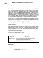
Scope
The purpose of this document is to describe how to interface with the PCI-16SDI Windows
NT Device Driver developed by General Standards Corporation (GSC). This software
provides the interface between "Application Software" and the PCI-16SDI Board. The
interface to this board is at the device level. It requires no knowledge of the actual board
addressing or device register contents.
The PCI-16SDI Driver Software executes under control of the Windows NT operating
system. The PCI-16SDI is implemented as a standard Windows NT device driver written in
the ‘C’ programming language. The PCI-16SDI Driver Software is designed to operate on
CPU boards containing standard x86 processors.
3
WIndows NT PCI-16SDI Driver User’s Manual for x86 Processors
11/22/00
2.
Hardware Overview
The General Standards Corporation (GSC) PCI-16SDI board is a 16-Bit, 16-Channel SigmaDelta, 220 KSPS Analog Input PCI Board. Each of the sigma-delta analog input channels can
be controlled by any one of four independent sample clocks and multiple channels can be
harmonically locked together. A/D conversions on multiple boards can be synchronized and
phase-locked. Sample rates are adjustable from 5 KSPS to 220 KSPS, and the input range is
software selectable as +/-1.25V, +/-2.5V, +/-5V or +/-10V. Internal autocalibration
networks permit periodic calibration to be performed without removing the board from the
system.
The PCI-16SDI board includes a DMA controller and 256K samples of FIFO buffering. The
board also provides for interrupt generation for various states of the board, including operation
complete, sample buffer threshold transition and sample buffer almost empty and full.
4
WIndows NT PCI-16SDI Driver User’s Manual for x86 Processors
11/22/00
3.
Referenced Documents
The following documents provide reference material for the PCI-16SDI Board:
•
PCI-16SDI User’s Manual - General Standards Corporation.
•
PLX Technology, Inc. PCI 9080 PCI Bus Master Interface Chip data sheet.
5
WIndows NT PCI-16SDI Driver User’s Manual for x86 Processors
11/22/00
4.
Driver Interface
The PCI-16SDI Driver conforms to the device driver standards required by the Windows NT
Operating System and contains the following standard driver entry points.
•
CreateFile() - opens a driver interface to one PCI-16SDI Card
•
CloseHandle() - closes a driver interface to one PCI-16SDI Card
•
ReadFile() - reads A/D Samples received from a PCI-16SDI Card
•
DeviceIoControl() - performs various control and setup functions on the PCI-16SDI
Card
The PCI-16SDI Device Driver provides a standard driver interface to the GSC PCI-16SDI
card for Windows NT applications which run on a x86 target processor. The device driver is
installed and devices are created when the driver is started during boot up. The functions of
the driver can then be used to access the board. Devices are created with the name “sdix”
where ‘x’ is the device number. Device numbers start at 0 for Windows NT applications and
1 for DOS applications. For each PCI-16SDI board found, the device number increments.
Included in the device driver software package is a menu driven board application program
and source code. This program is delivered undocumented and unsupported but may be used
to exercise the PCI-16SDI card and device driver. It can also be used to break the learning
curve somewhat for programming the PCI-16SDI device.
It is important to note that the PCI-16SDI device driver is target processor dependent. System
calls are made within the driver which are only available on x86 processors.
When the driver is installed during the power up of the computer, certain default values are set
by the driver. These values are not reset to the default values every time the user calls the
CreateFile function. The following default values are set:
Ø Read Timeout
= 10 seconds
Ø DMA Enable
= Disabled
6
WIndows NT PCI-16SDI Driver User’s Manual for x86 Processors
11/22/00
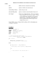
4.1.
CreateFile()
The CreateFile() function is the standard NT entry point to open a connection to a PCI-16SDI
Card. This function must be called before any other driver function may be called to control
the device.
The fdwAttrsAndFlags parameter needs to be set to
FILE_FLAG_OVERLAPPED if overlapped I/O is to be performed. Using overlapped I/O
for reads allows the calling task to continue executing while the driver is performing the I/O
operation and making calls to GetOverlappedResult() to determine when the operation is
complete. See the SDITest sample code for a example on how to perform overlapped I/O.
Multiple tasks may call CreateFile to access the driver for the same board. The programmer
needs to be very careful if this is desirable. One task may set values that conflict with the other
task.
PROTOTYPE:
HANDLE CreateFile(LPCTSTR
DWORD
DWORD
LPSECURITY_ATTRIBUTES
DWORD
DWORD
HANDLE
lpszName,
fdwAccess,
fdwShareMode,
lpsa,
fdwCreate,
fdwAttrsAndFlags,
hTemplateFile);
Where:
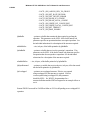
lpszName - name of the device being opened which is “sdix” where x is the device number.
Device numbers begin with 0 for NT applications and 1 for DOS applications.
Each device is consecutively numbered after that.
fdwAccess – a logically or’ed combination of one or more of the following access modes:
GENERIC_ALL
- Execute, Read and Write Access
GENERIC_EXECUTE - Execute Access
GENERIC_READ
- Read Access
GENERIC_WRITE
- Write Access
Use (GENERIC_WRITE | GENERIC_READ) for this parameter.
fdwShareMode – a logically or’ed combination of zero or more of the following share options:
FILE_SHARE_READ - Read Share Mode
FILE_SHARE_WRITE - Write Share Mode
7
WIndows NT PCI-16SDI Driver User’s Manual for x86 Processors
11/22/00
This parameter is usually zero.
lpsa – a pointer to a security attributes structure.
This parameter is usually NULL.
fdwCreate – a logically or’ed combination of one or more of the following device creation
options:
CREATE_NEW
CREATE_ALWAYS
OPEN_EXISTING
OPEN_ALWAYS
TRUNCATE_EXISTING
- Create new file
- Always create file
- Open existing file/device
- Always open file
- Truncate file
Use OPEN_EXISTING for this parameter.
fdwAttrsAndFlags – a logically or’ed combination of zero or more of the following attributes
and flags:
FILE_ATTRIBUTE_READONLY
- Read-only file/device
FILE_ATTRIBUTE_HIDDEN
- Hidden file
FILE_ATTRIBUTE_SYSTEM
- System file
FILE_ATTRIBUTE_DIRECTORY
- Directory file
FILE_ATTRIBUTE_ARCHIVE
- Archive file
FILE_ATTRIBUTE_NORMAL
- Normal file/device
FILE_ATTRIBUTE_TEMPORARY
- Temporary file
FILE_FLAG_WRITE_THROUGH
- Write through access
FILE_FLAG_OVERLAPPED
- Overlapped access
FILE_FLAG_NO_BUFFERING
- No buffering
FILE_FLAG_RANDOM_ACCESS
- Random Access
FILE_FLAG_SEQUENTIAL_SCAN
- Sequential Scan
FILE_FLAG_DELETE_ON_CLOSE
- Delete file on Close
FILE_FLAG_BACKUP_SEMANTICS
- Backup semantics
FILE_FLAG_POSIX_SEMANTICS
- POSIX semantics
FILE_FLAG_OPEN_REPARSE_POINT - Open reparse point
FILE_FLAG_OPEN_NO_RECALL
- Open no recall
Use either FILE_ATTRIBUTE_NORMAL or FILE_ATTRIBUTE_OVERLAPPED for
this parameter. Use FILE_ATTRIBUTE_OVERLAPPED if you plan to use overlapped
I/O.
hTemplateFile – handle to a template file.
8
WIndows NT PCI-16SDI Driver User’s Manual for x86 Processors
11/22/00
Use NULL for this parameter.
Returns a handle to the device opened on success. This handle is then used as a parameter to
all other device accesses. Returns a NULL when the create fails.
EXAMPLE:
HANDLE
DWORD
hDevice;
dwErrorCode;
/*
Open the PCI-16SDI device sdi1
*/
hDevice = CreateFile(“\\\\.\\sdi1”, GENERIC_READ | GENERIC_WRITE, 0,
NULL, OPEN_EXISTING, FILE_FLAG_OVERLAPPED, NULL);
if (hDevice == INVALID_HANDLE_VALUE)
{
dwErrorCode = GetLastError();
ErrorMessage(“CreateFile”, dwErrorCode);
ExitProcess(dwErrorCode);
}
/* Access the device here. */
/* Close the device here. */
9
WIndows NT PCI-16SDI Driver User’s Manual for x86 Processors
11/22/00
4.2.
CloseHandle()
The CloseHandle() function is the driver entry point to close a connection to a PCI-16SDI
Card. This function should only be called after the CreateFile() function has been successfully
called for a PCI-16SDI Card. The CloseHandle() function closes an interface to a PCI16SDI device.
If multiple tasks have created connections to the driver using the CreateFile function, the
CloseHandle call will only close the connection for that particular task.
PROTOTYPE:
BOOL CloseHandle(HANDLE hObject);
Where:
hObject - handle to the device to close. The return parameter from a
CreateFile() call.
Returns TRUE if successful or FALSE if unsuccessful.
EXAMPLE:
HANDLE
DWORD
hDevice;
dwErrorCode;
/* Open the device and get hDevice here. */
/* Access the device here. */
/*
if
{
Close the SDI Device. */
(! CloseHandle(hDevice))
dwErrorCode = GetLastError();
ErrorMessage(“CloseHandle”, dwErrorCode);
}
hDevice = NULL;
10
WIndows NT PCI-16SDI Driver User’s Manual for x86 Processors
11/22/00
4.3.
ReadFile()
The ReadFile() function is the driver entry point to read A/D sample data from a PCI-16SDI
Card. This function should only be called after the CreateFile() function has been successfully
called for a PCI-16SDI Card. The ReadFile() function reads the number of bytes requested
from the receive FIFO by the NumberOfBytesToRead parameter. Note that this parameter
is the number of bytes, not the number of words. Therefore, the number of samples to be
read should be multiplied by four for this parameter. If the device was selected for overlapped
I/O in the CreateFile() call, this function may return without any words being read and a call to
the GetOverlappedResult() needs to be made to determine when the operation completes.
If multiple tasks try to access the ReadFile function at the same time, the driver will process
each request in the order they are received. This function will perform programmed I/O (PIO)
or Direct Memory Access (DMA) transfers depending upon whether DMA is enabled using
the IOCTL_SDI_SET_DMA_ENABLE ioctl() function call. DMA transfers allow the reading
of the samples to be achieved without using CPU time allowing the application to perform
operations concurrently.
If this function is called to read more samples than currently exist in the board buffer, the data
read after the buffer is emptied will be invalid. It is up to the application to ensure that more
data is not requested than exists in the buffer. This can be accomplished by using the interrupt
notification ioctl() function to indicate to the application when the buffer threshold has been
exceeded or the sample buffer is almost full.
The format of each sample word read is as follows:
Bits D19-D16
Channel Tag (0-15)
Bits D15-D0
16-bit A/D Sample Value in either Offset Binary or Two’s
Complement depending on the setting of the
IOCTL_SDI_SET_DATA_FORMAT ioctl() function
PROTOTYPE:
BOOL ReadFile( HANDLE
LPVOID
DWORD
LPDWORD
LPOVERLAPPED
hFile,
lpBuffer,
NumberOfBytesToRead,
lpNumberOfBytesRead,
lpOverlapped);
Where:
11
WIndows NT PCI-16SDI Driver User’s Manual for x86 Processors
11/22/00
hFile
- handle to the device returned from CreateFile()
lpBuffer
- pointer to a buffer to store the data read
NumberOfBytesToRead
- number of bytes to read
lpNumberOfBytesRead
- pointer to a location to return the number of bytes read
lpOverlapped
- pointer to an overlapped structure. If device was opened
using overlapped I/O, this structure is required. If device
was not opened using overlapped I/O, this parameter
should be NULL. See WIN32 documentation for a
structure definition and the SDITest Program for an
example of how to use it.
Returns TRUE on success. Returns FALSE on failure or if I/O is still pending on an
overlapped I/O operation.
EXAMPLE:
#define NUM_SAMPLES 80
HANDLE
hDevice;
ULONG
ulBuffer[NUM_SAMPLES];
DWORD
dwBytesRead = 0;
DWORD
dwErrorCode;
BOOL
status;
/* Read from the PCI-16SDI device */
status = ReadFile(hDevice, ulBuffer, NUM_SAMPLES*4,
&dwBytesRead, NULL);
if (! status)
{
dwErrorCode = GetLastError();
ErrorMessage(“ReadFile”, dwErrorCode);
}
else
{
if (dwBytesRead != (NUM_SAMPLES*4))
{
printf(“Only read %d bytes\n”, dwBytesRead);
}
else
{
/* Data read OK. Use the data here. */
}
}
12
WIndows NT PCI-16SDI Driver User’s Manual for x86 Processors
11/22/00
4.4.
DeviceIoControl()
The DeviceIoControl() function is the device entry point to perform control and setup
operations on a PCI-16SDI Card. This function should only be called after the CreateFile()
function has been successfully called for a PCI-16SDI Card. The DeviceIoControl() function
will perform different functions based upon the dwIoControlCode parameter. These functions
will be described in the following subparagraphs.
Certain DeviceIoControl function calls should not be used unless absolutely necessary. These
routines are provided so that the driver is complete and does not limit the use of the PCI16SDI board. Each of the subsections that follow will describe the limitations on their use.
PROTOTYPE:
BOOL DeviceIoControl(HANDLE
DWORD
LPVOID
DWORD
LPVOID
DWORD
LPDWORD
LPOVERLAPPED
hDevice,
dwIoControlCode,
lpInBuffer,
nInBufferSize,
lpOutBuffer,
nOutBufferSize,
lpBytesReturned,
lpOverlapped);
Where:
hDevice
- handle to the device returned from CreateFile()
dwIoControlCode
- control code for the operation to perform. One of the following
constants from the include file “SDIIoctl.h”:
- IOCTL_SDI_NO_COMMAND
- IOCTL_SDI_READ_REGISTER
- IOCTL_SDI_WRITE_REGISTER
- IOCTL_SDI_REQ_INT_NOTIFY
- IOCTL_SDI_SET_INPUT_RANGE
- IOCTL_SDI_SET_INPUT_MODE
- IOCTL_SDI_SET_SW_SYNC
- IOCTL_SDI_AUTO_CAL
- IOCTL_SDI_INITIALIZE
- IOCTL_SDI_SET_DATA_FORMAT
- IOCTL_SDI_SET_INITIATOR_MODE
- IOCTL_SDI_SET_BUFFER_THRESHOLD
- IOCTL_SDI_CLEAR_BUFFER
- IOCTL_SDI_SET_ACQUIRE_MODE
- IOCTL_SDI_SET_GEN_RATE
13
WIndows NT PCI-16SDI Driver User’s Manual for x86 Processors
11/22/00
- IOCTL_SDI_ASSIGN_GEN_TO_GROUP
- IOCTL_SDI_SET_RATE_DIVISOR
- IOCTL_SDI_GET_DEVICE_ERROR
- IOCTL_SDI_READ_PCI_CONFIG
- IOCTL_SDI_READ_LOCAL_CONFIG
- IOCTL_SDI_WRITE_PCI_CONFIG_REG
- IOCTL_SDI_WRITE_LOCAL_CONFIG_REG
- IOCTL_SDI_SET_TIMEOUT
- IOCTL_SDI_DMA_ENABLE
lpInBuffer
- pointer to a buffer that contains the data required to perform the
operation. This parameter can be NULL if the dwIoControlCode
parameter specifies an operation that does not require input data. See
the individual subsections for a description of the structures required.
nInBufferSize
- size, in bytes, of the buffer pointed to by lpInBuffer
lpOutBuffer
- pointer to a buffer that receives the operation’s output data. This
parameter can be NULL if the dwIoControlCode parameter specifies
an operation that does not produce output data. See the individual
subsections for a description of the structures required.
nOutBufferSize
- size, in bytes, of the buffer pointed to by lpOutBuffer
lpBytesReturned
- pointer to a variable that receives the size, in bytes, of the data stored
into the buffer pointed to by lpOutbuffer.
lpOverlapped
- pointer to an overlapped structure. If device was opened
using overlapped I/O, this structure is required. If device
was not opened using overlapped I/O, this parameter
should be NULL. See WIN32 documentation for a
structure definition and the SDITest Program for an example of how to
use it.
Returns TRUE if successful or FALSE on failure or if I/O is still pending on an overlapped I/O
operation.
14
WIndows NT PCI-16SDI Driver User’s Manual for x86 Processors
11/22/00
4.4.1.
IOCTL_SDI_NO_COMMAND
This is an empty driver entry point. This command may be given to validate that the driver
is correctly installed and that the PCI-16SDI Board Device has been successfully opened.
Input/Output Buffer:
not used
EXAMPLE:
HANDLE
DWORD
DWORD
hDevice;
dwErrorCode;
dwTransferSize;
if (! DeviceIoControl(hDevice, IOCTL_SDI_NO_COMMAND, NULL, 0,
NULL, 0, &dwTransferSize, NULL))
{
dwErrorCode = GetLastError();
ErrorMessage("DeviceIoControl", dwErrorCode);
}
15
WIndows NT PCI-16SDI Driver User’s Manual for x86 Processors
11/22/00
4.4.2.
IOCTL_SDI_READ_REGISTER
The IOCTL_SDI_READ_REGISTER function reads and returns the contents of one of
the PCI-16SDI Registers.
Input/Output Buffer:
<from SDIIoctl.h>
typedef struct _SDI_REGISTER_PARAMS
{
ULONG eSDIRegister;
ULONG ulRegisterValue;
} SDI_REGISTER_PARAMS, *PSDI_REGISTER_PARAMS;
Where ulRegisterValue will store the value read from the register
and eSDIRegister is one of the following:
#define
#define
#define
#define
#define
#define
#define
#define
#define
#define
#define
#define
#define
#define
#define
#define
BOARD_CTRL_REG
RATE_CTRL_A_REG
RATE_CTRL_B_REG
RATE_CTRL_C_REG
RATE_CTRL_D_REG
RATE_ASSIGN_REG
RATE_DIVISOR_00_01_REG
RATE_DIVISOR_02_03_REG
RATE_DIVISOR_04_05_REG
RATE_DIVISOR_06_07_REG
RATE_DIVISOR_08_09_REG
RATE_DIVISOR_10_11_REG
RATE_DIVISOR_12_13_REG
RATE_DIVISOR_14_15_REG
BUFFER_THRESHOLD_REG
INPUT_DATA_BUFFER_REG
16
0
1
2
3
4
5
6
7
8
9
10
11
12
13
14
18
WIndows NT PCI-16SDI Driver User’s Manual for x86 Processors
11/22/00
EXAMPLE:
HANDLE
DWORD
DWORD
SDI_REGISTER_PARAMS
SDI_REGISTER_PARAMS
hDevice;
dwTransferSize;
dwErrorCode;
InputRegData;
OutputRegData;
InputRegData.eSDIRegister
= BOARD_CTRL_REG;
OutputRegData.ulRegisterValue = 0xDEADBEEF;
if ((! DeviceIoControl(hDevice, IOCTL_SDI_READ_REGISTER,
&InputRegData, sizeof(SDI_REGISTER_PARAMS),
&OutputRegData, sizeof(SDI_REGISTER_PARAMS),
&dwTransferSize, NULL)) ||
(dwTransferSize != sizeof(SDI_REGISTER_PARAMS)))
{
dwErrorCode = GetLastError();
ErrorMessage("DeviceIoControl", dwErrorCode);
}
else
{
printf("Board Control Register = %08lx\n”,
OutputRegData.ulRegisterValue);
}
17
WIndows NT PCI-16SDI Driver User’s Manual for x86 Processors
11/22/00
4.4.3.
IOCTL_SDI_WRITE_REGISTER
The IOCTL_SDI_WRITE_REGISTER function writes a value to one of the PCI-16SDI
Registers. The user should be very careful modifying values of certain registers. All SDI
Registers may be manipulated using the driver’s ioctl() functions. It is recommended that
the ioctl() functions be used instead of the IOCTL_SDI_WRITE_REGISTER routine.
Input/Output Buffer:
<from SDIIoctl.h>
typedef struct _SDI_REGISTER_PARAMS
{
ULONG eSDIRegister;
ULONG ulRegisterValue;
} SDI_REGISTER_PARAMS, *PSDI_REGISTER_PARAMS;
Where ulRegisterValue contains the value to be written to the
register and eSDIRegister is one of the following:
#define
#define
#define
#define
#define
#define
#define
#define
#define
#define
#define
#define
#define
#define
#define
#define
BOARD_CTRL_REG
RATE_CTRL_A_REG
RATE_CTRL_B_REG
RATE_CTRL_C_REG
RATE_CTRL_D_REG
RATE_ASSIGN_REG
RATE_DIVISOR_00_01_REG
RATE_DIVISOR_02_03_REG
RATE_DIVISOR_04_05_REG
RATE_DIVISOR_06_07_REG
RATE_DIVISOR_08_09_REG
RATE_DIVISOR_10_11_REG
RATE_DIVISOR_12_13_REG
RATE_DIVISOR_14_15_REG
BUFFER_THRESHOLD_REG
INPUT_DATA_BUFFER_REG
18
0
1
2
3
4
5
6
7
8
9
10
11
12
13
14
18
WIndows NT PCI-16SDI Driver User’s Manual for x86 Processors
11/22/00
EXAMPLE:
HANDLE
DWORD
DWORD
SDI_REGISTER_PARAMS
hDevice;
dwTransferSize;
dwErrorCode;
InputRegData;
InputRegData.eSDIRegister
= BUFFER_THRESHOLD_REG;
InputRegData.ulRegisterValue = 0x0003FF00;
if (! DeviceIoControl(hDevice, IOCTL_SDI_WRITE_REGISTER,
&InputRegData, sizeof(SDI_REGISTER_PARAMS),
NULL, 0, &dwTransferSize, NULL))
{
dwErrorCode = GetLastError();
ErrorMessage("DeviceIoControl", dwErrorCode);
}
19
WIndows NT PCI-16SDI Driver User’s Manual for x86 Processors
11/22/00
4.4.4.
IOCTL_SDI_REQ_INT_NOTIFY
The IOCTL_SDI_REQ_INT_NOTIFY function will request that the driver notify the
application via an event when a specified interrupt occurs. The board only allows one
interrupt condition to be enabled at once, therefore only one interrupt condition can be
requested for notification. Notification of the following interrupt conditions can be
requested:
Ø Initialization Complete
Ø Auto Calibration Complete
Ø Channels Ready
Ø Buffer Threshold Low To High Transition
Ø Buffer Threshold High To Low Transition
Ø Buffer Almost Empty
Ø Buffer Almost Full
The driver uses interrupts for certain operations in response to requests from the
application. If the application requests an interrupt notification and then performs an
operation that requires the driver to use the interrupts, the driver may miss the notification
interrupt and not notify the application. The application should avoid the use of the
following ioctl() operations that require the use of interrupts when waiting on an interrupt
notification:
ioctl() Operation
Interrupt Condition Used
Ø IOCTL_SDI_SET_INPUT_RANGE
Channels Ready
Ø IOCTL_SDI_SET_INPUT_MODE
Channels Ready
Ø IOCTL_SDI_AUTO_CAL
Auto Calibration Complete
Ø IOCTL_SDI_INITIALIZE
Initialization Complete
Ø IOCTL_SDI_SET_GEN_RATE
Channels Ready
Ø IOCTL_SDI_ASSIGN_GEN_TO_GROUP Channels Ready
Ø IOCTL_SDI_SET_RATE_DIVISOR
20
Channels Ready
WIndows NT PCI-16SDI Driver User’s Manual for x86 Processors
11/22/00
If the application requests notification of the same interrupt that the driver needs to use, the
driver will use it and the application will get a notification.
Input/Output Buffer:
<from SDIIoctl.h>
typedef struct _SDI_REGISTER_PARAMS
{
ULONG eIntConditions;
HANDLE hEvent;
} SDI_INT_NOTIFY_PARAMS, *PSDI_INT_NOTIFY_PARAMS;
Where hEvent contains a handle of the event to be signaled when the
interrupt occurs and eIntConditions contains one of the following
conditions to be notified of.
#define
#define
#define
#define
#define
#define
#define
INIT_COMPLETE
AUTOCAL_COMPLETE
CHANNELS_READY
BUFFER_THRES_LOW_TO_HIGH
BUFFER_THRES_HIGH_TO_LOW
BUFFER_ALMOST_EMPTY
BUFFER_ALMOST_FULL
21
0
1
2
3
4
5
6
WIndows NT PCI-16SDI Driver User’s Manual for x86 Processors
11/22/00
EXAMPLE:
HANDLE
DWORD
DWORD
HANDLE
SDI_INT_NOTIFY_PARAMS
hDevice;
dwTransferSize;
dwErrorCode;
hEvent;
IntNotify;
IntNotify.eIntConditions = AUTOCAL_COMPLETE;
hEvent
= CreateEvent(NULL, FALSE, FALSE, NULL);
IntNotify.hEvent
= hEvent;
if (! DeviceIoControl(hDevice, IOCTL_SDI_REQ_INT_NOTIFY,
&IntNotify, sizeof(SDI_INT_NOTIFY_PARAMS),
NULL, 0, &dwTransferSize, NULL))
{
dwErrorCode = GetLastError();
ErrorMessage("DeviceIoControl", dwErrorCode);
}
if (! DeviceIoControl(hDevice, IOCTL_SDI_AUTO_CAL,
NULL, 0, NULL, 0,
&dwTransferSize, &overlap))
{
dwErrorCode = GetLastError();
ErrorMessage("DeviceIoControl", dwErrorCode);
}
// Wait ten seconds for Auto Calibration Interrupt.
if (WaitForSingleObject(hEvent, 10000) == WAIT_OBJECT_0)
{
printf("Interrupt Occurred\n");
}
else
{
printf("Timed Out Waiting for Interrupt \n");
}
22
WIndows NT PCI-16SDI Driver User’s Manual for x86 Processors
11/22/00
4.4.5.
IOCTL_SDI_SET_INPUT_RANGE
The IOCTL_SDI_SET_INPUT_RANGE function will set the SDI Analog Input Range to
+/-1.25V, +/-2.5V, +/-5V or +/-10V. This function may be used in overlapped mode
because the hardware needs time to settle. If the board is accessed before the settling
time, results may be indeterminate. The user should not access this function while data
sampling is in progress.
Input/Output Buffer:
<from SDIIoctl.h>
// Parameter = ULONG *pInputRange;
//
RANGE: 0-3
#define
#define
#define
#define
RANGE_1p25V
RANGE_2p5V
RANGE_5V
RANGE_10V
0
1
2
3
23
WIndows NT PCI-16SDI Driver User’s Manual for x86 Processors
11/22/00
EXAMPLE:
HANDLE
DWORD
DWORD
ULONG
OVERLAPPED
hDevice;
dwTransferSize;
dwErrorCode;
ulInputRange;
overlap;
overlap.Offset
= 0;
overlap.OffsetHigh = 0;
overlap.hEvent
= CreateEvent(NULL, FALSE, FALSE, NULL);
ulInputRange = RANGE_5V;
if (! DeviceIoControl(hDevice, IOCTL_SDI_SET_INPUT_RANGE,
&ulInputRange, sizeof(ULONG),
NULL, 0, &dwTransferSize, &overlap))
{
dwErrorCode = GetLastError();
ErrorMessage("DeviceIoControl", dwErrorCode);
}
else
{
status = GetOverlappedResult(hDevice, &overlap,
&dwTransferSize, TRUE);
if (! status)
{
printf("GetOverlappedResult Failed\n");
dwErrorCode = GetLastError();
ErrorMessage("GetOverlappedResult", dwErrorCode);
}
}
24
WIndows NT PCI-16SDI Driver User’s Manual for x86 Processors
11/22/00
4.4.6.
IOCTL_SDI_SET_INPUT_MODE
The IOCTL_SDI_SET_INPUT_MODE function will set the Analog Input Mode to either
differential, single-ended, ZERO Test or VREF Test. This function may be used in
overlapped mode because the hardware needs time to settle. If the board is accessed
before the settling time, results may be indeterminate. The user should not access this
function while data sampling is in progress.
Input/Output Buffer:
<from SDIIoctl.h>
// Parameter = ULONG *pInputMode;
//
RANGE: 0-3
#define
#define
#define
#define
MODE_DIFFERENTIAL
MODE_SINGLE_ENDED
MODE_ZERO_TEST
MODE_VREF_TEST
0
1
2
3
25
WIndows NT PCI-16SDI Driver User’s Manual for x86 Processors
11/22/00
EXAMPLE:
HANDLE
DWORD
DWORD
ULONG
OVERLAPPED
hDevice;
dwTransferSize;
dwErrorCode;
ulInputMode;
overlap;
overlap.Offset
= 0;
overlap.OffsetHigh = 0;
overlap.hEvent
= CreateEvent(NULL, FALSE, FALSE, NULL);
ulInputMode = MODE_SINGLE_ENDED;
if (! DeviceIoControl(hDevice, IOCTL_SDI_SET_INPUT_MODE,
&ulInputMode, sizeof(ULONG),
NULL, 0, &dwTransferSize, &overlap))
{
dwErrorCode = GetLastError();
ErrorMessage("DeviceIoControl", dwErrorCode);
}
else
{
status = GetOverlappedResult(hDevice, &overlap,
&dwTransferSize, TRUE);
if (! status)
{
printf("GetOverlappedResult Failed\n");
dwErrorCode = GetLastError();
ErrorMessage("GetOverlappedResult", dwErrorCode);
}
}
26
WIndows NT PCI-16SDI Driver User’s Manual for x86 Processors
11/22/00
4.4.7.
IOCTL_SDI_SET_SW_SYNC
The IOCTL_SDI_SET_SW_SYNC function will initiate a local ADC sync operation. It
may also generate an external sync output if the Initiator Mode is selected.
Input/Output Buffer:
NONE
EXAMPLE:
HANDLE
DWORD
DWORD
hDevice;
dwTransferSize;
dwErrorCode;
if (! DeviceIoControl(hDevice, IOCTL_SDI_SET_SW_SYNC,
NULL, 0, NULL, 0, &dwTransferSize, NULL))
{
dwErrorCode = GetLastError();
ErrorMessage("DeviceIoControl", dwErrorCode);
}
27
WIndows NT PCI-16SDI Driver User’s Manual for x86 Processors
11/22/00
4.4.8.
IOCTL_SDI_AUTO_CAL
The IOCTL_SDI_AUTO_CAL function will command the SDI Board to perform an Auto
Calibration. Auto Calibration will calibrate all input channels to a single internal voltage
reference. Offset and gain error corrections for each channel are implemented with
hardware DACs that retain the correction values until power is removed from the board or
another calibration is performed. This function may be used in overlapped mode because
the hardware needs time to complete the operation. If the board is accessed before the
settling time, results may be indeterminate. The user should not access this function while
data sampling is in progress.
Input/Output Buffer:
NONE
EXAMPLE:
HANDLE
DWORD
DWORD
OVERLAPPED
hDevice;
dwTransferSize;
dwErrorCode;
overlap;
overlap.Offset
= 0;
overlap.OffsetHigh = 0;
overlap.hEvent
= CreateEvent(NULL, FALSE, FALSE, NULL);
if (! DeviceIoControl(hDevice, IOCTL_SDI_AUTO_CAL,
NULL, 0, NULL, 0, &dwTransferSize, &overlap))
{
dwErrorCode = GetLastError();
ErrorMessage("DeviceIoControl", dwErrorCode);
}
else
{
status = GetOverlappedResult(hDevice, &overlap,
&dwTransferSize, TRUE);
if (! status)
{
printf("GetOverlappedResult Failed\n");
dwErrorCode = GetLastError();
ErrorMessage("GetOverlappedResult", dwErrorCode);
}
}
28
WIndows NT PCI-16SDI Driver User’s Manual for x86 Processors
11/22/00
4.4.9.
IOCTL_SDI_INITIALIZE
The IOCTL_SDI_INITIALIZE function will cause the internal logic to be initialized. The
following is performed by the initialize command:
Ø Calibration D/A converters are initialized with midrange values
Ø Rate Generators adjusted to 125 KSPS
Ø Rate generator A controls all channels
Ø Divisor ratios are set to 5 (sample rates to 25 kHz)
Ø Analog Input Buffer Empty
Ø Buffer Threshold to 0x0003FFFE
Ø Input Range set to +/-10V
Ø Input Mode set to Differential
Ø Board Control Register Initialized
Ø Local Interrupt Request Asserted for Initialization Complete
This function may be used in overlapped mode because the hardware needs time to settle.
If the board is accessed before the settling time, results may be indeterminate. The user
should not access this function while data sampling is in progress.
Input/Output Buffer:
NONE
29
WIndows NT PCI-16SDI Driver User’s Manual for x86 Processors
11/22/00
EXAMPLE:
HANDLE
DWORD
DWORD
OVERLAPPED
hDevice;
dwTransferSize;
dwErrorCode;
overlap;
overlap.Offset
= 0;
overlap.OffsetHigh = 0;
overlap.hEvent
= CreateEvent(NULL, FALSE, FALSE, NULL);
if (! DeviceIoControl(hDevice, IOCTL_SDI_INITIALIZE,
NULL, 0, NULL, 0, &dwTransferSize, &overlap))
{
dwErrorCode = GetLastError();
ErrorMessage("DeviceIoControl", dwErrorCode);
}
else
{
status = GetOverlappedResult(hDevice, &overlap,
&dwTransferSize, TRUE);
if (! status)
{
printf("GetOverlappedResult Failed\n");
dwErrorCode = GetLastError();
ErrorMessage("GetOverlappedResult", dwErrorCode);
}
}
30
WIndows NT PCI-16SDI Driver User’s Manual for x86 Processors
11/22/00
4.4.10.
IOCTL_SDI_SET_DATA_FORMAT
The IOCTL_SDI_SET_DATA_FORMAT function sets the data format to either Offset
Binary or Two’s Complement. The user should not access this function while data sampling
is in progress.
ANALOG INPUT LEVEL
OFFSET
BINARY
TWO’S
COMPLEMENT
Positive Full Scale minus 1 LSB
0xFFFF
0x7FFF
Zero plus 1 LSB
0x8001
0x0001
Zero
0x8000
0x0000
Zero minus 1 LSB
0x7FFF
0xFFFF
Negative Full Scale plus 1 LSB
0x0001
0x8001
Negative Full Scale
0x0000
0x8000
Input/Output Buffer:
<from SDIIoctl.h>
// Parameter = ULONG *pDataFormat;
//
RANGE: 0-1
#define FORMAT_TWOS_COMPLEMENT 0
#define FORMAT_OFFSET_BINARY
1
31
WIndows NT PCI-16SDI Driver User’s Manual for x86 Processors
11/22/00
EXAMPLE:
HANDLE
DWORD
DWORD
ULONG
hDevice;
dwTransferSize;
dwErrorCode;
ulDataFormat;
ulDataFormat = FORMAT_TWOS_COMPLEMENT;
if (! DeviceIoControl(hDevice, IOCTL_SDI_SET_DATA_FORMAT,
&ulDataFormat, sizeof(ULONG),
NULL, 0, &dwTransferSize, NULL))
{
dwErrorCode = GetLastError();
ErrorMessage("DeviceIoControl", dwErrorCode);
}
32
WIndows NT PCI-16SDI Driver User’s Manual for x86 Processors
11/22/00
4.4.11.
IOCTL_SDI_SET_INITIATOR_MODE
The IOCTL_SDI_SET_INITIATOR_MODE function allows selection of how this board
will participate in multiple board synchronization. The board may be selected as an initiator
or a target. Selecting the initiator mode will allow other boards to synchronize to this
board’s sampling clock and synchronization commands. Selecting target mode will allow
this board to synchronize to an external sampling clock and synchronization commands.
The external source may be another PCI-16SDI board.
Input/Output Buffer:
<from SDIIoctl.h>
// Parameter = ULONG *pInitTarget;
//
RANGE: 0-1
#define TARGET_MODE
0
#define INITIATOR_MODE 1
EXAMPLE:
HANDLE
DWORD
DWORD
ULONG
hDevice;
dwTransferSize;
dwErrorCode;
ulInitTarget;
ulInitTarget = INITIATOR_MODE;
if (! DeviceIoControl(hDevice, IOCTL_SDI_SET_INITIATOR_MODE,
&ulInitTarget, sizeof(ULONG),
NULL, 0, &dwTransferSize, NULL))
{
dwErrorCode = GetLastError();
ErrorMessage("DeviceIoControl", dwErrorCode);
}
33
WIndows NT PCI-16SDI Driver User’s Manual for x86 Processors
11/22/00
4.4.12.
IOCTL_SDI_SET_BUFFER_THRESHOLD
The IOCTL_SDI_SET_BUFFER_THRESHOLD function will set the threshold that will
be used to indicate when a threshold interrupt should occur. The threshold interrupt may
be used to determine how much sampling data is contained in the board data buffer.
Interrupts may be generated based upon when the amount of data exceeds the threshold or
based upon when the amount of data goes below the threshold.
Input/Output Buffer:
<from SDIIoctl.h>
// Parameter = ULONG *pulThreshold;
//
RANGE: 0x0 - 0x3FFFF
EXAMPLE:
HANDLE
DWORD
DWORD
ULONG
hDevice;
dwTransferSize;
dwErrorCode;
ulThreshold;
ulThreshold = 0x0003FF00;
if (! DeviceIoControl(hDevice, IOCTL_SDI_SET_BUFFER_THRESHOLD,
&ulThreshold, sizeof(ULONG),
NULL, 0, &dwTransferSize, NULL))
{
dwErrorCode = GetLastError();
ErrorMessage("DeviceIoControl", dwErrorCode);
}
34
WIndows NT PCI-16SDI Driver User’s Manual for x86 Processors
11/22/00
4.4.13.
IOCTL_SDI_CLEAR_BUFFER
The IOCTL_SDI_CLEAR_BUFFER function will empty the contents of the sample
buffer.
Input/Output Buffer:
NONE
EXAMPLE:
HANDLE
DWORD
DWORD
hDevice;
dwTransferSize;
dwErrorCode;
if (! DeviceIoControl(hDevice, IOCTL_SDI_CLEAR_BUFFER,
NULL, 0, NULL, 0, &dwTransferSize, NULL))
{
dwErrorCode = GetLastError();
ErrorMessage("DeviceIoControl", dwErrorCode);
}
35
WIndows NT PCI-16SDI Driver User’s Manual for x86 Processors
11/22/00
4.4.14.
IOCTL_SDI_SET_ACQUIRE_MODE
The IOCTL_SDI_SET_ACQUIRE_MODE function will enable or disable the SDI card
from acquiring sample data and storing it in the buffer.
Input/Output Buffer:
<from SDIIoctl.h>
// Parameter = ULONG *pAcquireMode;
//
RANGE: 0-1
#define START_ACQUIRE 0
#define STOP_ACQUIRE 1
EXAMPLE:
HANDLE
DWORD
DWORD
ULONG
hDevice;
dwTransferSize;
dwErrorCode;
ulAcquireMode;
ulAcquireMode = START_ACQUIRE;
if (! DeviceIoControl(hDevice, IOCTL_SDI_SET_ACQUIRE_MODE,
&ulAcquireMode, sizeof(ULONG),
NULL, 0, &dwTransferSize, NULL))
{
dwErrorCode = GetLastError();
ErrorMessage("DeviceIoControl", dwErrorCode);
}
36
WIndows NT PCI-16SDI Driver User’s Manual for x86 Processors
11/22/00
4.4.15.
IOCTL_SDI_SET_GEN_RATE
The IOCTL_SDI_SET_GEN_RATE function will set the rate for one of the four
generators on the SDI Board. This function may be used in overlapped mode because the
hardware needs time to settle. If the board is accessed before the settling time, results may
be indeterminate. The user should not access this function while data sampling is in
progress.
Input/Output Buffer:
<from SDIIoctl.h>
// Parameter = GEN_RATE_PARAMS *pRateParams;
// Send in Generator Frequency (floating point in kHz)
// to get the Generator Rate to send as ulNrate in
// IOCTL_SDI_SET_GEN_RATE.
#define Fgen_To_Nrate(Fgen)
\
((Fgen < MIN_FGEN) ? MIN_NRATE : \
((Fgen > MAX_FGEN) ? MAX_NRATE : \
ROUND_TO_ULONG((Fgen * GEN_MULT) - GEN_OFFSET)))
#define
#define
#define
#define
GEN_A
GEN_B
GEN_C
GEN_D
0
1
2
3
typedef struct _GEN_RATE_PARAMS
{
ULONG eGenerator; // RANGE: 0-3
ULONG ulNrate;
// RANGE: 0-0x1FF
} GEN_RATE_PARAMS, *PGEN_RATE_PARAMS;
37
WIndows NT PCI-16SDI Driver User’s Manual for x86 Processors
11/22/00
EXAMPLE:
HANDLE
DWORD
DWORD
OVERLAPPED
GEN_RATE_PARAMS
hDevice;
dwTransferSize;
dwErrorCode;
overlap;
GenRate;
overlap.Offset
= 0;
overlap.OffsetHigh = 0;
overlap.hEvent
= CreateEvent(NULL, FALSE, FALSE, NULL);
// Set parameters for 11.264 MHz
GenRate.eGenerator = GEN_A;
GenRate.ulNrate
= Fgen_To_Nrate(11264);
// in KHz
if (! DeviceIoControl(hDevice, IOCTL_SDI_SET_GEN_RATE,
&GenRate, sizeof(GEN_RATE_PARAMS),
NULL, 0, &dwTransferSize, &overlap))
{
dwErrorCode = GetLastError();
ErrorMessage("DeviceIoControl", dwErrorCode);
}
else
{
status = GetOverlappedResult(hDevice, &overlap,
&dwTransferSize, TRUE);
if (! status)
{
printf("GetOverlappedResult Failed\n");
dwErrorCode = GetLastError();
ErrorMessage("GetOverlappedResult", dwErrorCode);
}
}
38
WIndows NT PCI-16SDI Driver User’s Manual for x86 Processors
11/22/00
4.4.16.
IOCTL_SDI_ASSIGN_GEN_TO_GROUP
The IOCTL_SDI_ASSIGN_GEN_TO_GROUP function will assign a generator to one of
the four channel groups. The assigned generator may be one of the four generators (A-D)
or an external sample clock. The channels in each group are different based upon how
many channels are on the board as follows:
CHANNEL
GROUP
16-CHANNEL
BOARD
8-CHANNEL
BOARD
4-CHANNEL
BOARD
0
00, 01, 02, 03
00, 01
00
1
04, 05, 06, 07
02, 03
01
2
08, 09, 10, 11
04, 05
02
3
12, 13, 14, 15
06, 07
03
This function may be used in overlapped mode because the hardware needs time to settle.
If the board is accessed before the settling time, results may be indeterminate. The user
should not access this function while data sampling is in progress.
Input/Output Buffer:
<from SDIIoctl.h>
// Groups
#define GRP_0
#define GRP_1
#define GRP_2
#define GRP_3
0
1
2
3
// Generator Assignments
#define ASN_GEN_A
0
#define ASN_GEN_B
1
#define ASN_GEN_C
2
#define ASN_GEN_D
3
#define ASN_EXT_CLK 4
#define ASN_GEN_NONE 5
typedef struct _GEN_ASSIGN_PARAMS
{
39
WIndows NT PCI-16SDI Driver User’s Manual for x86 Processors
11/22/00
ULONG eGroup;
// RANGE: 0-3
ULONG eGenAssign; // RANGE: 0-5
} GEN_ASSIGN_PARAMS, *PGEN_ASSIGN_PARAMS;
EXAMPLE:
HANDLE
DWORD
DWORD
OVERLAPPED
GEN_ASSIGN_PARAMS
hDevice;
dwTransferSize;
dwErrorCode;
overlap;
GenAssign;
overlap.Offset
= 0;
overlap.OffsetHigh = 0;
overlap.hEvent
= CreateEvent(NULL, FALSE, FALSE, NULL);
GenAssign.eGroup
= GRP_0;
GenAssign.eGenAssign = ASN_GEN_A;
if (! DeviceIoControl(hDevice, IOCTL_SDI_ASSIGN_GEN_TO_GROUP,
&GenAssign, sizeof(GEN_ASSIGN_PARAMS),
NULL, 0, &dwTransferSize, &overlap))
{
dwErrorCode = GetLastError();
ErrorMessage("DeviceIoControl", dwErrorCode);
}
else
{
status = GetOverlappedResult(hDevice, &overlap,
&dwTransferSize, TRUE);
if (! status)
{
printf("GetOverlappedResult Failed\n");
dwErrorCode = GetLastError();
ErrorMessage("GetOverlappedResult", dwErrorCode);
}
}
40
WIndows NT PCI-16SDI Driver User’s Manual for x86 Processors
11/22/00
4.4.17.
IOCTL_SDI_SET_RATE_DIVISOR
The IOCTL_SDI_SET_RATE_DIVISOR function sets the value that divides the assigned
rate generator frequency for a specified channel. This function may be used in overlapped
mode because the hardware needs time to settle. If the board is accessed before the
settling time, results may be indeterminate. The user should not access this function while
data sampling is in progress.
Input/Output Buffer:
<from SDIIoctl.h>
//
//
//
//
Send in Generator Frequency (floating point in kHz)
and Sample Rate (floating point in kHz) to
Fgen_and_Fsamp_To_Ndiv to get the Rate Divisor to
send as ulDivisor in IOCTL_SDI_SET_RATE_DIVISOR.
#define Fgen_and_Fsamp_To_Ndiv(Fgen,Fsamp)
\
((Ndiv(Fgen,Fsamp) < MIN_NDIV) ? MIN_NDIV : \
((Ndiv(Fgen,Fsamp) > MAX_NDIV) ? MAX_NDIV : \
Ndiv(Fgen,Fsamp)))
typedef struct _RATE_DIVISOR_PARAMS
{
ULONG ulChannel; // RANGE 0-15
ULONG ulDivisor; // RANGE 1-32
} RATE_DIVISOR_PARAMS, *PRATE_DIVISOR_PARAMS;
41
WIndows NT PCI-16SDI Driver User’s Manual for x86 Processors
11/22/00
EXAMPLE:
HANDLE
DWORD
DWORD
OVERLAPPED
RATE_DIVISOR_PARAMS
hDevice;
dwTransferSize;
dwErrorCode;
overlap;
RateDivisor;
overlap.Offset
= 0;
overlap.OffsetHigh = 0;
overlap.hEvent
= CreateEvent(NULL, FALSE, FALSE, NULL);
// Set Channel 5 divisor for generator frequency of 11.264 MHz and
// sample rate of 44 kHz.
RateDivisor.ulChannel = 5;
RateDivisor.ulDivisor = Fgen_and_Fsamp_To_Ndiv(11264.0, 44.0);
if (! DeviceIoControl(hDevice, IOCTL_SDI_SET_RATE_DIVISOR,
&RateDivisor, sizeof(RATE_DIVISOR_PARAMS),
NULL, 0, &dwTransferSize, &overlap))
{
dwErrorCode = GetLastError();
ErrorMessage("DeviceIoControl", dwErrorCode);
}
else
{
status = GetOverlappedResult(hDevice, &overlap,
&dwTransferSize, TRUE);
if (! status)
{
printf("GetOverlappedResult Failed\n");
dwErrorCode = GetLastError();
ErrorMessage("GetOverlappedResult", dwErrorCode);
}
}
42
WIndows NT PCI-16SDI Driver User’s Manual for x86 Processors
11/22/00
4.4.18.
IOCTL_SDI_GET_DEVICE_ERROR
The IOCTL_SDI_GET_DEVICE_ERROR function will return the error that occurred on
the last call to one of the PCI-16SDI Device Driver entry points. Whenever a driver
function is called and it returns an error, this function may be called to determine the cause
of the error.
Input/Output Buffer:
<from SDIIoctl.h>
// Parameter = ULONG *pulDeviceError;
//
RANGE: 0-8
#define
#define
#define
#define
#define
#define
#define
#define
#define
SDI_SUCCESS
SDI_INVALID_PARAMETER
SDI_INVALID_BUFFER_SIZE
SDI_PIO_TIMEOUT
SDI_DMA_TIMEOUT
SDI_IOCTL_TIMEOUT
SDI_OPERATION_CANCELLED
SDI_RESOURCE_ALLOCATION_ERROR
SDI_INVALID_REQUEST
0
1
2
3
4
5
6
7
8
EXAMPLE:
HANDLE
DWORD
DWORD
ULONG
hDevice;
dwTransferSize;
dwErrorCode;
DeviceError;
if ((! DeviceIoControl(hDevice, IOCTL_SDI_GET_DEVICE_ERROR,
NULL, 0, &DeviceError,
sizeof(ULONG), &dwTransferSize, NULL)) ||
(dwTransferSize != sizeof(ULONG)))
{
dwErrorCode = GetLastError();
ErrorMessage("DeviceIoControl", dwErrorCode);
}
43
WIndows NT PCI-16SDI Driver User’s Manual for x86 Processors
11/22/00
4.4.19.
IOCTL_SDI_READ_PCI_CONFIG
The IOCTL_SDI_READ_PCI_CONFIG function will read all of the PCI Configuration
Registers.
Input/Output Buffer:
<from SDIIoctl.h>
typedef struct _SDI_READ_PCI_CONFIG_PARAM
{
ULONG ulDeviceVendorID;
ULONG ulStatusCommand;
ULONG ulClassCodeRevisionID;
ULONG ulBISTHdrTypeLatTimerCacheLineSize;
ULONG ulRuntimeRegAddr;
ULONG ulConfigRegAddr;
ULONG ulPCIBaseAddr2;
ULONG ulPCIBaseAddr3;
ULONG ulUnusedBaseAddr1;
ULONG ulUnusedBaseAddr2;
ULONG ulCardbusCISPtr;
ULONG ulSubsystemVendorID;
ULONG ulPCIRomAddr;
ULONG ulReserved1;
ULONG ulReserved2;
ULONG ulMaxLatMinGntIntPinIntLine;
} SDI_READ_PCI_CONFIG_PARAM, *PSDI_READ_PCI_CONFIG_PARAM;
44
WIndows NT PCI-16SDI Driver User’s Manual for x86 Processors
11/22/00
EXAMPLE:
HANDLE
DWORD
DWORD
SDI_READ_PCI_CONFIG_PARAM
hDevice;
dwTransferSize;
dwErrorCode;
ConfigRegs;
if ((! DeviceIoControl(hDevice, IOCTL_SDI_READ_PCI_CONFIG, NULL, 0,
&ConfigRegs,
sizeof(SDI_READ_PCI_CONFIG_PARAM),
&dwTransferSize, NULL)) ||
(dwTransferSize != sizeof(SDI_READ_PCI_CONFIG_PARAM)))
{
dwErrorCode = GetLastError();
ErrorMessage("DeviceIoControl", dwErrorCode);
}
else
{
printf("Device ID/Vendor ID Reg = %08lx\n",
ConfigRegs.ulDeviceVendorID);
printf("Status/Command Reg = %08lx\n",
ConfigRegs.ulStatusCommand);
printf("Class Code/Revision ID Reg = %08lx\n",
ConfigRegs.ulClassCodeRevisionID);
printf("BIST/Header Type/Lat Timer/Cache Line Size Reg = 08lx\n",
ConfigRegs.ulBISTHdrTypeLatTimerCacheLineSize);
printf("Runtime Register Address Reg = %08lx\n",
ConfigRegs.ulRuntimeRegAddr);
printf("Config Register Address Reg = %08lx\n",
ConfigRegs.ulConfigRegAddr);
printf("PCI Base Address 2 Reg = %08lx\n",
ConfigRegs.ulPCIBaseAddr2);
printf("PCI Base Address 3 Reg = %08lx\n",
ConfigRegs.ulPCIBaseAddr3);
printf("Unused Base Address 1 Reg = %08lx\n",
ConfigRegs.ulUnusedBaseAddr1);
printf("Unused Base Address 2 Reg = %08lx\n",
ConfigRegs.ulUnusedBaseAddr2);
printf("Cardbus CIS Pointer Reg = %08lx\n",
ConfigRegs.ulCardbusCISPtr);
printf("Subsystem ID/Vendor ID Reg = %08lx\n",
ConfigRegs.ulSubsystemVendorID);
printf("PCI Rom Address Reg = %08lx\n",
ConfigRegs.ulPCIRomAddr);
printf("Reserved 1 Reg = %08lx\n",
ConfigRegs.ulReserved1);
printf("Reserved 2 Reg = %08lx\n",
ConfigRegs.ulReserved2);
printf("Max Lat/Min Gnt/Int Pin/Int Line Reg = %08lx\n",
ConfigRegs.ulMaxLatMinGntIntPinIntLine);
}
45
WIndows NT PCI-16SDI Driver User’s Manual for x86 Processors
11/22/00
4.4.20.
IOCTL_SDI_READ_LOCAL_CONFIG
The IOCTL_SDI_READ_LOCAL_CONFIG function will read and return the local
configuration registers.
Input/Output Buffer:
<from SDIIoctl.h>
typedef struct _CONFIG_REGS_PARAMS
{
/*** Local Configuration Registers ***/
ULONG
ulPciLocRange0;
ULONG
ulPciLocRemap0;
ULONG
ulModeArb;
ULONG
ulEndianDescr;
ULONG
ulPciLERomRange;
ULONG
ulPciLERomRemap;
ULONG
ulPciLBRegDescr0;
ULONG
ulLocPciRange;
ULONG
ulLocPciMemBase;
ULONG
ulLocPciIOBase;
ULONG
ulLocPciRemap;
ULONG
ulLocPciConfig;
ULONG
ulOutPostQIntStatus;
ULONG
ulOutPostQIntMask;
UCHAR
uchReserved1[8];
/*** Shared Run Time Registers ***/
ULONG
ulMailbox[8];
ULONG
ulPciLocDoorBell;
ULONG
ulLocPciDoorBell;
ULONG
ulIntCntrlStat;
ULONG
ulRunTimeCntrl;
ULONG
ulDeviceVendorID;
ULONG
ulRevisionID;
ULONG
ulMailboxReg0;
ULONG
ulMailboxReg1;
/*** Local DMA Registers ***/
ULONG
ulDMAMode0;
ULONG
ulDMAPCIAddress0;
ULONG
ulDMALocalAddress0;
ULONG
ulDMAByteCount0;
ULONG
ulDMADescriptorPtr0;
ULONG
ulDMAMode1;
ULONG
ulDMAPCIAddress1;
ULONG
ulDMALocalAddress1;
ULONG
ulDMAByteCount1;
46
WIndows NT PCI-16SDI Driver User’s Manual for x86 Processors
11/22/00
ULONG
ULONG
ULONG
ULONG
UCHAR
ulDMADescriptorPtr1;
ulDMACmdStatus;
ulDMAArbitration;
ulDMAThreshold;
uchReserved3[12];
/*** Messaging Queue Registers ***/
ULONG
ulMsgUnitCfg;
ULONG
ulQBaseAddr;
ULONG
ulInFreeHeadPtr;
ULONG
ulInFreeTailPtr;
ULONG
ulInPostHeadPtr;
ULONG
ulInPostTailPtr;
ULONG
ulOutFreeHeadPtr;
ULONG
ulOutFreeTailPtr;
ULONG
ulOutPostHeadPtr;
ULONG
ulOutPostTailPtr;
ULONG
ulQStatusCtrl;
UCHAR
uchReserved4[4];
ULONG
ulPciLocRange1;
ULONG
ulPciLocRemap1;
ULONG
ulPciLBRegDescr1;
} CONFIG_REGS, *PCONFIG_REGS;
EXAMPLE:
HANDLE
DWORD
DWORD
CONFIG_REGS
hDevice;
dwTransferSize;
dwErrorCode;
LocalConfigRegs;
if ((! DeviceIoControl(hDevice, IOCTL_SDI_READ_LOCAL_CONFIG, NULL,
0, &LocalConfigRegs, sizeof(CONFIG_REGS),
&dwTransferSize, NULL)) ||
(dwTransferSize != sizeof(CONFIG_REGS)))
{
dwErrorCode = GetLastError();
ErrorMessage("DeviceIoControl", dwErrorCode);
}
else
{
printf("\n");
printf("
LOCAL CONFIGURATION REGISTERS\n");
printf("Range for PCI to Local 0 Reg
= %08lx\n",
LocalConfigRegs.ulPciLocRange0);
printf("Remap for PCI to Local 0 Reg
= %08lx\n",
LocalConfigRegs.ulPciLocRemap0);
printf("Mode Arbitration Reg
= %08lx\n",
LocalConfigRegs.ulModeArb);
printf("Big/Little Endian Descr. Reg
= %08lx\n",
LocalConfigRegs.ulEndianDescr);
47
WIndows NT PCI-16SDI Driver User’s Manual for x86 Processors
11/22/00
printf("Range for PCI to Local Reg
=
LocalConfigRegs.ulPciLERomRange);
printf("Remap for PCI to Local Reg
=
LocalConfigRegs.ulPciLERomRemap);
printf("Bus Region Descriptions for Reg =
LocalConfigRegs.ulPciLBRegDescr0);
printf("Range for Local to PCI Reg
=
LocalConfigRegs.ulLocPciRange);
printf("Base Addr for Local to PCI Reg =
LocalConfigRegs.ulLocPciMemBase);
printf("Base Addr for Local to PCI Reg =
LocalConfigRegs.ulLocPciIOBase);
printf("Remap for Local to PCI Reg
=
LocalConfigRegs.ulLocPciRemap);
printf("PCI Config Address Reg for Reg =
LocalConfigRegs.ulLocPciConfig);
printf("Range for PCI to Local 1 Reg
=
LocalConfigRegs.ulPciLocRange1);
printf("Remap for PCI to Local 1 Reg
=
LocalConfigRegs.ulPciLocRemap1);
printf("Bus Region Descriptor Reg
=
LocalConfigRegs.ulPciLBRegDescr1);
%08lx\n",
%08lx\n",
%08lx\n",
%08lx\n",
%08lx\n",
%08lx\n",
%08lx\n",
%08lx\n",
%08lx\n",
%08lx\n",
%08lx\n",
printf("
RUNTIME REGISTERS\n");
printf("Mailbox Register 0
= %08lx\n",
LocalConfigRegs.ulMailbox[0]);
printf("Mailbox Register 1
= %08lx\n",
LocalConfigRegs.ulMailbox[1]);
printf("Mailbox Register 2
= %08lx\n",
LocalConfigRegs.ulMailbox[2]);
printf("Mailbox Register 3
= %08lx\n",
LocalConfigRegs.ulMailbox[3]);
printf("Mailbox Register 4
= %08lx\n",
LocalConfigRegs.ulMailbox[4]);
printf("Mailbox Register 5
= %08lx\n",
LocalConfigRegs.ulMailbox[5]);
printf("Mailbox Register 6
= %08lx\n",
LocalConfigRegs.ulMailbox[6]);
printf("Mailbox Register 7
= %08lx\n",
LocalConfigRegs.ulMailbox[7]);
printf("PCI to Local Doorbell Reg
= %08lx\n",
LocalConfigRegs.ulPciLocDoorBell);
printf("Local to PCI Doorbell Reg
= %08lx\n",
LocalConfigRegs.ulLocPciDoorBell);
printf("Interrupt Control/Status
= %08lx\n",
LocalConfigRegs.ulIntCntrlStat);
printf("EEPROM Control, PCI Command = %08lx\n",
LocalConfigRegs.ulRunTimeCntrl);
printf("Device ID
= %08lx\n",
LocalConfigRegs.ulDeviceVendorID);
printf("Revision ID
= %08lx\n",
LocalConfigRegs.ulRevisionID);
printf("Mailbox Register 0
= %08lx\n",
LocalConfigRegs.ulMailboxReg0);
48
WIndows NT PCI-16SDI Driver User’s Manual for x86 Processors
11/22/00
printf("Mailbox Register 1
= %08lx\n",
LocalConfigRegs.ulMailboxReg1);
printf("
DMA REGISTERS\n");
printf("dma channel 0 mode Reg
= %08lx\n",
LocalConfigRegs.ulDMAMode0);
printf("dma channel 0 pci address Reg
= %08lx\n",
LocalConfigRegs.ulDMAPCIAddress0);
printf("dma channel 0 local address Reg = %08lx\n",
LocalConfigRegs.ulDMALocalAddress0);
printf("dma channel 0 transfer byte Reg = %08lx\n",
LocalConfigRegs.ulDMAByteCount0);
printf("dma channel 0 descriptor Reg
= %08lx\n",
LocalConfigRegs.ulDMADescriptorPtr0);
printf("dma channel 1 mode Reg
= %08lx\n",
LocalConfigRegs.ulDMAMode1);
printf("dma channel 1 pci address Reg
= %08lx\n",
LocalConfigRegs.ulDMAPCIAddress1);
printf("dma channel 1 local address Reg = %08lx\n",
LocalConfigRegs.ulDMALocalAddress1);
printf("dma channel 1 transfer byte Reg = %08lx\n",
LocalConfigRegs.ulDMAByteCount1);
printf("dma channel 1 descriptor Reg
= %08lx\n",
LocalConfigRegs.ulDMADescriptorPtr1);
printf("dma command/status registers Reg = %08lx\n",
LocalConfigRegs.ulDMACmdStatus);
printf("dma arbitration register Reg
= %08lx\n",
LocalConfigRegs.ulDMAArbitration);
printf("dma threshold register Reg
= %08lx\n",
LocalConfigRegs.ulDMAThreshold);
printf("MESSAGING QUEUE REGISTERS\n");
printf("outbound post queue Int Status Reg =
LocalConfigRegs.ulOutPostQIntStatus);
printf("outbound post queue Int Mask Reg
=
LocalConfigRegs.ulOutPostQIntMask);
printf("Mailbox Reg 0
=
LocalConfigRegs.ulMailbox[0]);
printf("Mailbox Reg 1
=
LocalConfigRegs.ulMailbox[1]);
printf("messaging unit configuration Reg
=
LocalConfigRegs.ulMsgUnitCfg);
printf("queue base address register Reg
=
LocalConfigRegs.ulQBaseAddr);
printf("inbound free head pointer Reg
=
LocalConfigRegs.ulInFreeHeadPtr);
printf("inbound free tail pointer Reg
=
LocalConfigRegs.ulInFreeTailPtr);
printf("inbound post head pointer Reg
=
LocalConfigRegs.ulInPostHeadPtr);
printf("inbound post tail pointer Reg
=
LocalConfigRegs.ulInPostTailPtr);
printf("inbound free head pointer Reg
=
LocalConfigRegs.ulOutFreeHeadPtr);
49
%08lx\n",
%08lx\n",
%08lx\n",
%08lx\n",
%08lx\n",
%08lx\n",
%08lx\n",
%08lx\n",
%08lx\n",
%08lx\n",
%08lx\n",
WIndows NT PCI-16SDI Driver User’s Manual for x86 Processors
11/22/00
printf("inbound free tail pointer Reg
LocalConfigRegs.ulOutFreeTailPtr);
printf("inbound post head pointer Reg
LocalConfigRegs.ulOutPostHeadPtr);
printf("inbound post tail pointer Reg
LocalConfigRegs.ulOutPostTailPtr);
printf("queue status/control Reg
LocalConfigRegs.ulQStatusCtrl);
}
50
= %08lx\n",
= %08lx\n",
= %08lx\n",
= %08lx\n",
WIndows NT PCI-16SDI Driver User’s Manual for x86 Processors
11/22/00
4.4.21.
IOCTL_SDI_WRITE_PCI_CONFIG_REG
The IOCTL_SDI_WRITE_PCI_CONFIG_REG function will write a value to one of the
PCI Configuration Registers. The user should be very careful modifying values of certain
registers. The following registers should not be changed:
•
PCI_MEM_BASE_ADDR
•
PCI_IO_BASE_ADDR
•
PCI_BASE_ADDR_0
•
PCI_BASE_ADDR_1
•
PCI_BASE_ADDR_LOC_ROM
Input/Output Buffer:
<from SDIIoctl.h>
typedef struct _SDI_REGISTER_PARAMS
{
ULONG eSDIRegister;
ULONG ulRegisterValue;
} SDI_REGISTER_PARAMS, *PSDI_REGISTER_PARAMS;
Where ulRegisterValue contains the value to be written to the
register and eSDIRegister is one of the following:
#define
#define
#define
#define
#define
#define
#define
#define
STATUS_COMMAND
1
BIST_HDR_TYPE_LAT_CACHE_SIZE 3
PCI_MEM_BASE_ADDR
4
PCI_IO_BASE_ADDR
5
PCI_BASE_ADDR_0
6
PCI_BASE_ADDR_1
7
PCI_BASE_ADDR_LOC_ROM
12
LAT_GNT_INT_PIN_LINE
15
51
WIndows NT PCI-16SDI Driver User’s Manual for x86 Processors
11/22/00
EXAMPLE:
HANDLE
DWORD
DWORD
SDI_REGISTER_PARAMS
hDevice;
dwTransferSize;
dwErrorCode;
InputRegData;
InputRegData.eSDIRegister
= STATUS_COMMAND;
InputRegData.ulRegisterValue = 0x12345678;
if (! DeviceIoControl(hDevice, IOCTL_SDI_WRITE_PCI_CONFIG_REG,
&InputRegData, sizeof(SDI_REGISTER_PARAMS),
NULL, 0, &dwTransferSize, NULL))
{
dwErrorCode = GetLastError();
ErrorMessage("DeviceIoControl", dwErrorCode);
}
52
WIndows NT PCI-16SDI Driver User’s Manual for x86 Processors
11/22/00
4.4.22.
IOCTL_SDI_WRITE_LOCAL_CONFIG_REG
The IOCTL_SDI_WRITE_LOCAL_CONFIG_REG function will write a value to one of
the Local Configuration Registers. The user should be very careful modifying values of
certain registers. All of the DMA Registers should not be changed while a data transfer is
in progress. The following registers should not be changed:
•
All Local Configuration Registers
Input/Output Buffer:
<from SDIIoctl.h>
typedef struct _SDI_REGISTER_PARAMS
{
ULONG eSDIRegister;
ULONG ulRegisterValue;
} SDI_REGISTER_PARAMS, *PSDI_REGISTER_PARAMS;
Where ulRegisterValue contains the value to be written to the
register and eSDIRegister is one of the following:
/*** DMA Registers ***/
#define DMA_CH_0_MODE
#define DMA_CH_0_PCI_ADDR
#define DMA_CH_0_LOCAL_ADDR
#define DMA_CH_0_TRANS_BYTE_CNT
#define DMA_CH_0_DESC_PTR
#define DMA_CH_1_MODE
#define DMA_CH_1_PCI_ADDR
#define DMA_CH_1_LOCAL_ADDR
#define DMA_CH_1_TRANS_BYTE_CNT
#define DMA_CH_1_DESC_PTR
#define DMA_CMD_STATUS
#define DMA_MODE_ARB_REG
#define DMA_THRESHOLD_REG
32
33
34
35
36
37
38
39
40
41
42
43
44
/*** Local Configuration Registers. ***/
#define PCI_TO_LOC_ADDR_0_RNG
0
#define LOC_BASE_ADDR_REMAP_0
1
#define MODE_ARBITRATION
2
#define BIG_LITTLE_ENDIAN_DESC
3
#define PCI_TO_LOC_ROM_RNG
4
#define LOC_BASE_ADDR_REMAP_EXP_ROM
5
#define BUS_REG_DESC_0_FOR_PCI_LOC
6
#define DIR_MASTER_TO_PCI_RNG
7
#define LOC_ADDR_FOR_DIR_MASTER_MEM
8
#define LOC_ADDR_FOR_DIR_MASTER_IO
9
#define PCI_ADDR_REMAP_DIR_MASTER
10
53
WIndows NT PCI-16SDI Driver User’s Manual for x86 Processors
11/22/00
#define
#define
#define
#define
PCI_CFG_ADDR_DIR_MASTER_IO
PCI_TO_LOC_ADDR_1_RNG
LOC_BASE_ADDR_REMAP_1
BUS_REG_DESC_1_FOR_PCI_LOC
11
92
93
94
/*** Run Time Registers ***/
#define MAILBOX_REGISTER_0
#define MAILBOX_REGISTER_1
#define MAILBOX_REGISTER_2
#define MAILBOX_REGISTER_3
#define MAILBOX_REGISTER_4
#define MAILBOX_REGISTER_5
#define MAILBOX_REGISTER_6
#define MAILBOX_REGISTER_7
#define PCI_TO_LOC_DOORBELL
#define LOC_TO_PCI_DOORBELL
#define INT_CTRL_STATUS
#define PROM_CTRL_CMD_CODES_CTRL
#define DEVICE_ID_VENDOR_ID
#define REVISION_ID
#define MAILBOX_REG_0
#define MAILBOX_REG_1
16
17
18
19
20
21
22
23
24
25
26
27
28
29
30
31
/*** Messaging Queue Registers ***/
#define OUT_POST_Q_INT_STATUS
#define OUT_POST_Q_INT_MASK
#define IN_Q_PORT
#define OUT_Q_PORT
#define MSG_UNIT_CONFIG
#define Q_BASE_ADDR
#define IN_FREE_HEAD_PTR
#define IN_FREE_TAIL_PTR
#define IN_POST_HEAD_PTR
#define IN_POST_TAIL_PTR
#define OUT_FREE_HEAD_PTR
#define OUT_FREE_TAIL_PTR
#define OUT_POST_HEAD_PTR
#define OUT_POST_TAIL_PTR
#define Q_STATUS_CTRL_REG
12
13
16
17
48
49
50
51
52
53
54
55
56
57
58
54
WIndows NT PCI-16SDI Driver User’s Manual for x86 Processors
11/22/00
EXAMPLE:
HANDLE
DWORD
DWORD
SDI_REGISTER_PARAMS
hDevice;
dwTransferSize;
dwErrorCode;
InputRegData;
InputRegData.eSDIRegister
= MAILBOX_REGISTER_0;
InputRegData.ulRegisterValue = 0x99999999;
if (! DeviceIoControl(hDevice, IOCTL_SDI_WRITE_LOCAL_CONFIG_REG,
&InputRegData, sizeof(SDI_REGISTER_PARAMS),
NULL, 0, &dwTransferSize, NULL))
{
dwErrorCode = GetLastError();
ErrorMessage("DeviceIoControl", dwErrorCode);
}
55
WIndows NT PCI-16SDI Driver User’s Manual for x86 Processors
11/22/00
4.4.23.
IOCTL_SDI_SET_TIMEOUT
The IOCTL_SDI_SET_TIMEOUT function will set the timeout that the driver uses for
ending read operations when enough data is not available. The time is specified in seconds.
A –1 will indicate no timeout. The default time set when the driver is initialized is 10
seconds.
Input/Output Buffer:
<from SDIIoctl.h>
// Parameter = ULONG *pulTimeout;
//
RANGE: 0x0-0xFFFFFFFF, 0xFFFFFFFF=No Timeout
EXAMPLE:
HANDLE
DWORD
DWORD
ULONG
hDevice;
dwTransferSize;
dwErrorCode;
ulTimeout;
/* Set the time to never timeout. */
ulTimeout = -1L;
if (! DeviceIoControl(hDevice, IOCTL_SDI_SET_TIMEOUT,
&ulTimeout, sizeof(ULONG),
NULL, 0, &dwTransferSize, NULL))
{
dwErrorCode = GetLastError();
ErrorMessage("DeviceIoControl", dwErrorCode);
}
56
WIndows NT PCI-16SDI Driver User’s Manual for x86 Processors
11/22/00
4.4.24.
IOCTL_SDI_SET_DMA_ENABLE
The IOCTL_SDI_SET_DMA_ENABLE function will set the enable for DMA operations.
If DMA is enabled the driver will perform DMA reads when read operations are
requested. If DMA is not enabled the driver will just perform Programmed I/O transfers
when read operations are requested. DMA Operations allow the CPU to be freed up for
application use while the data is being transferred.
Input/Output Buffer:
// Parameter = BOOLEAN *pbDMAEnable;
//
RANGE: FALSE-TRUE
EXAMPLE:
HANDLE
DWORD
DWORD
BOOLEAN
hDevice;
dwTransferSize;
dwErrorCode;
bDMAEnable;
/* Enable DMA. */
bDMAEnable = TRUE;
if (! DeviceIoControl(hDevice, IOCTL_SDI_SET_DMA_ENABLE,
&bDMAEnable, sizeof(BOOLEAN),
NULL, 0, &dwTransferSize, NULL))
{
dwErrorCode = GetLastError();
ErrorMessage("DeviceIoControl", dwErrorCode);
}
57
WIndows NT PCI-16SDI Driver User’s Manual for x86 Processors
11/22/00
5.
Driver Installation
This section will describe the procedure for installing the PCI-16SDI Windows NT Driver.
The following is the installation procedure:
?
?
?
?
?
Insert the installation floppy disk into a 3 ½” floppy drive
Click on Run from the Start menu
Type in “A:\Setup.exe” and Click the OK button in the Run Dialog Box
Follow the instructions on the screen
Either allow the install program to reboot the computer or reboot it manually so the
driver will automatically be installed
The following files are installed in the selected directory by the install program:
?
?
?
?
?
?
SDIDriver.sys – a copy of the driver file that is installed in the O/S drivers directory
SDIIoctl.h – the ‘C’ header file that contains the driver access constants and
structures. This file should be #include’d in application code where the driver is
accessed.
SDITest.c – a ‘C’ source file containing an example program that shows how to
access each of the driver entry points
SDITest.exe – compiled version of SDITest.c that will allow menu access to
each of driver entry points
readme.txt – a file containing the latest information on the driver
Uninst.isu – a file containing information that allows the driver to be uninstalled
The driver is installed to be automatically started up when the computer is booted.
58
WIndows NT PCI-16SDI Driver User’s Manual for x86 Processors
11/22/00
6.
Test Program
This section will describe how to execute the test program installed with the PCI-16SDI driver.
The following is the procedure for executing the test program:
?
?
?
Start up a command prompt window
Change to the directory where the driver was installed
Type “SDITest \\.\sdix”, where x is the number of the PCI-16SDI board to
access, starting with 1 for the first board
59