1
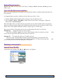
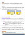
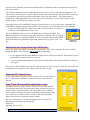
Curve Devil ® User Manual Revision E4 (01-28-09) For use with Curve Devil Ver 2.0.2.4 or higher Advent Ignitions, Inc. ■ 3154 E. La Palma Ave., Suite F ■ Anaheim, CA 92806 1 Table of Contents Installing Curve Devil®...............................................................................................................4 Simple 1, 2, 3 process ...........................................................................................................4 Curve Devil® installation ....................................................................................................4 Installing USB driver...................................................................................................................7 USB driver installation (Windows XP or Vista) ...................................................................7 Using the Curve Devil® Project Generator.................................................................................8 The Project .........................................................................................................................8 System Requirements: ........................................................................................................9 Curve Devil® Directories and files ........................................................................................9 Opening a new project ........................................................................................................9 Launch Curve Devil®: ......................................................................................................9 Editing Data Fields ..............................................................................................................10 Curve Table data entry: .................................................................................................10 Cut and Paste supported: ................................................................................................10 Copying data from another project ....................................................................................10 Ignition timing tables: .....................................................................................................11 Editing the ignition timing tables .......................................................................................12 Timing Limits .................................................................................................................13 Functions that modify the Ignition Timing Curve ..............................................................13 TPS (Throttle Position Sensor) .......................................................................................13 Altimeter .........................................................................................................................14 Timing Correction (Altitude Timing Correction) ...........................................................14 Rev Limiters .......................................................................................................................15 Single Stage Limiter .......................................................................................................15 Two Stage Limiter ..........................................................................................................15 Low Speed Limiter (Hole Shot): .....................................................................................15 Programming the Limiters ..................................................................................................15 Setting Limit RPMs .......................................................................................15 Low speed limiter ......................................................................................................16 Stage 1 Limiter ..........................................................................................................16 Two stage limiter .......................................................................................................16 Designing a Limiter algorithm ....................................................................................16 Editing the Rev Limiters ................................................................................................17 Designing a Rev Limiter profile .....................................................................................17 Considerations when designing a rev limiter profile ......................................................18 How aggressive do you want the rev limiting to be?...................................................18 Soft/Mild Limiter .......................................................................................................18 Hard/Aggressive Limiter ...........................................................................................18 Using the Two Stage Limiter ..............................................................................................19 Relays .......................................................................................................................................20 Relay Modes of operation ..................................................................................................20 Power Valve ....................................................................................................................20 Determining the Power Valve Open RPM value ...........................................................21 Alternate PV channel use ...............................................................................................21 Project Information note pad ...............................................................................................23 2 Find the engine’s TDC constant ..........................................................................................24 Compile test project #1 ....................................................................................................24 Compile test project #2 ....................................................................................................24 Download test program #1 ..............................................................................................24 Mount the timing tape to the PTO or coupler ..................................................................25 Take timing measurements .................................................................................................25 Set up to make measurement ..........................................................................................25 Perform the second TDC Calibration measurement .......................................................26 Reconfirm TDC setting .................................................................................................26 What do the test results mean? ........................................................................................26 CPS polarity ...................................................................................................................26 Reassemble engine .............................................................................................................27 ..................................................................................................................................................27 3 Installing Curve Devil® The Curve Devil® is the application software which runs on your XP laptop or desktop computer. It provides the means to configure the T4 ignition module. With the Curve Devil® you can select the specific functions you want your ignition to perform. This would include how many curve tables, rev limiters, water control, TPS etc. Once you have selected the features you can then populate each one with the data that suits your needs. When you have entered necessary data you can save the project to disk and proceed to download the data into your ignition via a USB cable. The Curve Devil® can be freely distributed and used to develop T4 ignition control projects. You could have a friend anywhere in the world develop T4 projects and e-mail them to you. Or, share projects with other riders who have a T4 ignition. Simple 1, 2, 3 process The process of designing a T4 project, then downloading it to your T4 ignition is straightforward and logical. ● Launch the Curve Devil® and open a new project ● Select the specific functions you wish your computer to control ● Enter the required data in each function window either by typing or cut and paste ● Compile your project. (convert your data into something the ignition understands) ● Connect the T4 to your computer via a USB cable (T4 can be installed in the boat) ● The GREEN light comes on telling you the Curve Devil® knows your T4 is connected ● Press the Read/Write button and follow a couple of instructions… Press PROGRAM … 10 seconds and you're done! Curve Devil® installation 1. Open the Advent Ignitions website. www.adventignitions.com 2. On the home page; Left click on the image as shown in Figure 1. 4 3. On the “Opening Setup.msi” window Click > “Save File”, see Figure 2 Save Setup.msi to your desk top or other convenient location. 4. Navigate to where you saved Setup.msi and... Click on filename: “Setup.msi”, see Figure 3. 5. In this screen, see Figure 4, the computer is ready to write the Setup.msi to the directory shown in the dialog box. For non-Vista OS let it do that click > Next. VISTA users: You must edit the Folder line in this window to read: C:\Advent Ignition\Curve Devil\ This will install the Curve Devil on the C:\ directory. The program will not properly install if Setup.msi it is put into the Program Files directory. 5 6. Click > Next to start the Curve Devil® Installation, see Figure 5 7. The notice in Figure 6 is expected, Click > Continue Anyway 8. The Curve Devil® is now installed, Click > Close to exit installation. Installation is complete... 6 Continue to the next section: “Installing USB driver” Installing USB driver In order for the Curve Devil® to communicate with a T4 ignition module over a USB connection the computer must have a special software driver installed. Most drivers are preloaded into newer versions of Windows, however the Curve Devil® uses a custom designed driver and therefore it must be installed on your computer.. USB driver installation (Windows XP or Vista) The USB driver is installed automatically when the Curve Devil® is installed. Continue to the next section: 7 Using the Curve Devil® Project Generator The Curve Devil® is the software application that allows the user to add, edit or remove, and all of the functional capabilities of the T4 ignition. It should be noted that not all features are available in all versions of the T4. As an example some engines don't support separate timing curves for each cylinder while others do. The Curve Devil® is designed to work with all models of T4. The Project The Curve Devil® is used to make and edit project files. A project is a list of selected functions and data which you input via the Curve Devil®. The projects data is then downloaded to the T4 ignition via the USB cable. Think of the project file as a spreadsheet file. In a spreadsheet you enter data in an organized manner. This data then causes the spreadsheet to produce results. The Curve Devil® is much the same, except the output of the project file defines how the ignition will function with various kinds of external inputs, such as RPM, throttle position, temperature, and altitude. 8 System Requirements: Windows XP, 2000, or Vista, 1024 x 768 Video, 512Mbytes DRAM, minimum 800Mhz processor, USB 2.0 port Curve Devil® Directories and files Before you start making your first project you should make folders to hold the data produced by the Curve Devil®. It is suggested that you make a folder on the foot directory of the C: drive. 1. Using the Windows File Explorer utility, navigate to the root directory of C:. 2. Click on FILE > NEW > FOLDER. A folder named “New Folder” will appear. Change the folder name to Advent Projects. This is the folder where you place all your project files. If you want to further divide your projects folder into different groups, simply make additional folders inside the Advent Projects folder. These folders can be used organize different customers, engine types, or vehicle types. These project folders will contain the two types of files produced by the Curve Devil®. Filename.prj – Output file when you save a project. When you select File > Open: you will see only filenames with the extension .prj since are the only file types that can be opened by the Curve Devil®. Filename.T4 - The output file when you 'Compile' a project. When you select the 'Read/Write' button to begin programming your ignition the file selection window will only display files with the extension .T4. These are the only files can be used by the Curve Devil® to program a T4 ignition. Opening a new project Launch Curve Devil®: 1.Left click on Tool Bar: File ►New ►Project, see Figure 1. 9 these that 2. Select Vehicle Make (fig 2), then Model (fig 3), then # of Cylinders. 2a. If the Vehicle Make and Model are not on the lists, choose Vehicle Make ►Custom x-coil, then number of Cylinders, 3. Feature Enable List box (Figure 4) opens, select from the list of available features those you want to use for the project. Open some or all of the functions you will be editing by using the function selection buttons. Edit all appropriate data fields to configure the ignition’s operation. Editing Data Fields Curve Table data entry: Ignition timing values may be entered to one decimal place. Values such as 0º,. 5º,16º, 27.3º are supported. Negative values (timing after top dead center) are not allowed. Example: -.1º, -5º. Values may be as large as the TDC Constant – 5º. Example: 58º - 5º = 53º. Cut and Paste supported: This is helpful when entering data into the curve tables where several entries are often the same value, or copying one table to another. Copying data from another project This is a handy way to reuse some or all the data from another project. Use this feature to copy selected function data from any named project to the current project. 10 To copy data begin by selecting FILE > IMPORT DATA, see Figure 5. Then answer yes or no to each function prompt that appears. Entering Yes will copy that data, No will not copy the data into the current project, see Figure 6. A directory window opens and you then negotiate to the folder and file you want to copy data from. You will be queried to import each function's data, click Yes/No as needed. Ignition timing tables: The T4 ignition supports separate ignition-timing tables for each cylinder, see Figures 7, 8 and 9. This means simply that each cylinder can have different ignition timing depending on specific physical features such as intake, exhaust and cylinder cooling differences. The upshot is that each cylinder can be tuned for maximum power rather than compromising if a single curve was used for all cylinders (as is the case for the most well-known after market ignition manufacturer). Twin cylinder engines that have one ignition coil cannot support separate timing curves due to certain electrical system limitations. These ignition systems are called wasted spark configuration, as both cylinders receive an ignition spark with the same timing on each rev, but only one-cylinder fires. The T4 ignition can accommodate separate ignition timing tables for all engines up to three timing tables, as selected in the Feature Enable window, see Figure 4. In the case of many two-cylinder ignitions with one coil there will be only one cylinder ignition-timing table per curve table. 11 Editing the ignition timing tables When you develop curve tables for your engine, generally large portions of all curves are the same. Most of the differences are in the higher RPM range. Use the Curve Devil® editing features to simplify the data input process. ● Cut & Paste: To eliminate the need to input the same numbers several times you can design one table and cut and paste into the other tables, then modify these as needed. ● Copy curves from another project using the Import Data command, see figures 5 and 6. 12 Timing Limits This function is designed to protect your engine from ignition timing values that could cause damage. This is an important function and should always be enabled. This function is not required where only the curve table defines the ignition timing. However, in more complex ignition configurations, such as when TPS and Altimeter timing table modifiers are used to increase engine performance, you may not know the actual timing your engine is going to get. With the Timing Limits function you can protect against several sources of ignition timing that can add up to potentially damaging values. Example: Engine safe timing limits of Min = 9.0°, Max = 38° BTDC _____________________ _Min Max_ Curve table timing range: 9.3º to 34.5º TPS timing range: -6.7º to 0.0º Altimeter range: 0.0º to 14.0º Total possible timing > 2.6º to 48.5º Minimum timing is violated by Maximum is violated by 12º - 2.6º = 9.3º 35º - 48.5º = 10.5º The example above shows that the actual ignition timing the engine can be subjected to can be well outside the safe limits. With the “Limits” function enabled and set to the proper values, the ignition timing will not exceed these values regardless of what the various timing control sources are telling the ignition to do. Read further to learn more about sources of timing control in your T4 ignition. Curve Devil warns of out-of-range timing values The last step in making a project before programming your ignition is depressing the “Compile” button. When you take this action the curve Devil first checks all active curve tables for values that are out of range. If any are found an error message is displayed and the offending timing curves are opened so you can easily edit the data. Functions that modify the Ignition Timing Curve TPS (Throttle Position Sensor) If your vehicle is fitted with a TPS you can utilize it to control deceleration detonation or performance advantages. The values in the TPS table are meant to retard (remove timing) from the ignition when you release the throttle. And when the throttle is pinned the TPS has no effect on the ignition timing, see Figure 12. However, you are free to do as you like here. 13 Altimeter The altimeter, shown in Figure 13 is an option in most T4 ignition models. The altimeter modifies the ignition-timing curve by adding timing as the vehicle altitude increases. The user may modify both the altitude values and insert any timing values as desired. Timing Correction (Altitude Timing Correction) In the case where your vehicle is at high altitude, usually higher than 3000 feet, you need to add ignition timing. The timing correction feature, see Figure 14, allows you to add (or remove) timing from the entire timing table as required for altitude. Add timing for higher altitude to provide a longer fuel burn time to compensate for the lower air density and oxygen content of the air. Entering a timing correction value: To advance timing enter a positive number; EI: Entering 3.8 will change 24º timing to 27.8º. To retard timing enter a negative number; EI: Entering -1.7 will change 24º timing to 22.3º. To enable Timing Correction the “Altimeter” must first be de-selected, then select “Timing Correction” in the Feature Enable window. Another use for the Timing Correction function Timing Correction accepts either positive or negative values to one decimal place. See Figure 14. This timing control can be an important aid during curve development. For example, when optimizing a new timing table you can employ the Timing Correction to advance or retard the entire curve as a way to determine if a section of the curve table needs tweaking without having to edit entry points of the curve table. Example 1: Engine is soft or loosing power: Enter 1º or 2º in the Timing Correction window, then run the engine in the problem RPM range. If performance improves, edit your ignition timing table to add that amount more timing. Example 2: The engine is detonating or otherwise has too much timing in an RPM range. Enter a small negative timing value in the Timing Correction window, like –1º, -1.7º , -2.5º and see what happens. A negative number offsets the entire curve downward by the entered value. 14 Rev Limiters The T4 ignition system supports three special purpose rev limiters • Single Stage Limiter • Dual Stage Limiter • Stutter Limiter (Hole Shot) Single Stage Limiter This is similar to the limiters in most original equipment ignitions, except you have complete control to customize the limit RPM and how the limiter works, such as softer or harder. Two Stage Limiter A second programmable limiter is appended to the single stage limiter to provide you more control of engine over-rev. The first stage limiter is typically set up as a softer limiter to just smooth out the short bursts of over revving. When the engine becomes “unhooked” for more than a short time, the RPM will rise to the second stage limit RPM and engage the second stage limiter. This limiter is usually set up to be much more aggressive to hold the engine at that crossover RPM. If there are problems with your current limiter loading up the engine and bogging when it comes out of the limiter, the Two Stage Limiter is the answer. Low Speed Limiter (Hole Shot): This limiter is used to hold the engine RPM at an acceptable level when the vehicle is on the starting line. The rider depresses and holds the low speed limiter button, then pins the throttle. When the race starts the limiter button is released, the throttle is already pinned, and off you go to the head of the pack.. The low speed limiter can be activated only while the engine is running. If you have a false start or release the button inadvertently you, must re-start the engine to reactivate the Stutter Limiter. The low speed limiter works as follows: 1. Start the engine, engine runs normally over the full RPM range 2. When in position at the starting line, depress and hold the low speed limiter button 3. Pin the throttle, the limiter holds the preset RPM 4. With the limiter button depressed you may run the engine at any RPM up to the limiter 5. On GO, release the button…the engine goes to max RPM quickly As a safety feature once the low speed limiter button is released, depressing the button again will have no effect. You must stop and re-start the engine to re-activate the low speed limiter. Programming the Limiters Overview: ● each of the limiter values may be set in 1 RPM increments ● Limiter action is fully programmable from very soft to hard limit ● Each cylinder within each limiter revolution can be set to “fire” or “no fire” ● Rev limiter can be set from 2 to 6 revolution limiter loops ● Provides variable limiter action to your requirements, no other ignition can do this Setting Limit RPMs Each of the three limiters have different types of RPM settings as required by the type of limiter. 15 Low speed limiter This limiter has a “Enter RPM” only, where Enter means the lowest RPM where the limiter is activated and remains active at any RPM above that value. In normal usage when the limiter is active, the engine will either be at idle or the throttle will be fully pinned where the engine is trying to go to a high RPM. Stage 1 Limiter This limiter has an Enter and Exit RPM. The Exit RPM can only be set to an RPM less than the Enter RPM. There is no case where you would want to have the limiter ON, then OFF at a higher RPM. The Exit RPM should be set at 50 or 100rpm below the Enter RPM. This allows the engine to have a well behaved limit action when the engine is running at or near the Enter RPM value. If the Enter/Exit RPM are set to same value the engine would quickly move in and out of rev limit resulting in uncontrolled and erratic rev limiter action. Two stage limiter The Stage 2 limiter is used in conjunction with the Stage 1 limiter. This linkage provides a single two stage limit action. This type of limiter works very well in conditions where the water or snow surface is variable. That is to say a mix of lite chop / wash board snow and large waves or icy surfaces. The limit action starts with the Enter RPM of limiter 1, the Limiter 1 Exit RPM is where Limiter 1 stops and Limiter 2 takes over. Limiter 2 remains active at any RPM above this transition RPM. Note that the Exit RPM of Limiter 1 can only be set to an RPM higher than the Enter RPM in this limiter mode. Designing a Limiter algorithm Refer to the Rev Limiter image in Figure 15. You will note that each limiter has 6 rows labeled Rotation and each limiter has between 1 and 3 columns (depending on the selected engine), labeled Cylinder. Each limiter algorithm can be between 2 and 6 revolutions in length, then repeat until the engine exits the limiter. The user can define how the cylinders will fire during each revolution. Each cylinder, in each revolution, can be programmed to “Fire”, or “No Fire”. Disabling (X) any cylinder in a row causes that row and all rows to the end of rotation 6 to be removed from the loop. 16 The two limiter profiles (1-0) sequence are equivalent. The one on the left applies the same pattern for all 6 rotations, then repeats from rotation1. The one on the right applies the same pattern in rotation 1, then loops back on itself and repeats. By entering an X in any cylinder box of rotation 2, all following rotations to the end are disabled. Engine power is reduced to ½ or 50% power. These two limiter profiles (1-1-0-0 sequence) are equivalent. The one on the left applies the same 2 rotation patterns three times (3 & 4 the 5 & 6), then repeats from rotation 1. Editing the Rev Limiters Note the legend descriptions in the white box at the bottom of Figure 14. ● ● ● 0 = No Fire 1 = Fire X = Disable this rotation and through rotation 6 To change the values simply place the cursor over the desired rotation/cylinder and left click. Each click will cause a 0 – 1 – X to be displayed. Repeat for all other cylinder boxes. If you enter a single X in any cylinder box within a row, all cylinders in that row and through rotation 6 will be disabled; see Figure 16. To re-enable one or more rotation rows, place the cursor in any cylinder box in the first disabled row, then click to place a 0 or 1 there to enable that row, see Figure 17. Designing a Rev Limiter profile Designing a rev limiter is very important to the engine operation. A good design will protect the engine from over revving damage while not loosing excessive speed or not allowing the engine to bog down with excess unburnt fuel in the cylinders. You will find that a good rev limiter design will allow you to make your turns quicker with less loss of power and minimize pump cavitation when the pump unhooks in heavy chop. 17 Considerations when designing a rev limiter profile How aggressive do you want the rev limiting to be? Ideally, a rev limiter would hold the engine speed at the exact limit setting. In real life however, the engine RPM will generally increase when the limiter is engaged. Of course this is not true if the limiter disables all coil firing, which is the method used by some ignitions. The result of “no-fire” limiter is that the engine RPM and speed will plummet as well as bring down the nose of the boat while producing the feeling you’re about to be launched over the handle bars. These are things that should be avoided at all cost when racing. The other undesirable effect is that the engine will load up with unburnt fuel. This fuel will likely cause the engine to backfire or bog when the cylinders start firing when the limiter shuts off. A good limiter design will fire the coils often enough to burn all the fuel delivered to the engine during the limiter time. This firing may result in some rate of increase in RPM. The second stage limiter can then be used to further limit the increasing RPM. The Limiter should be designed so each cylinder is fired often enough to keep it clear of un-burnt fuel and seldom enough to keep the RPMs from increasing too much and to keep the nose up so as not loose too much speed. There are several ways to design a limiter that have the same result. The simplest design is often the best. The following designs provide the same performance… Limiter in Fig 18 repeats a 2-rotation pattern 3 times, then repeats the sequence. Limiter in Figure 19 acts the same as Figure 18, but has the 2-rotation pattern with the repeating patterns disabled. Limiter in Figure 20 is a different 2-rotation pattern but still reduces the engine power by the same amount as the others. All three designs fire all cylinders to ensure any unburnt fuel is burnt while reducing engine power to 50%. Soft/Mild Limiter The Limiter in Figure 21 fires 3, misses 1, then repeats. Engine power is reduced to 3 of 4 or 75% power. Hard/Aggressive Limiter The Limiter in Figure 22 fires 2, misses 4, then repeats. Engine power is reduced to 2 of 6 or 33% 18 Using the Two Stage Limiter A two stage limiter is useful if you’re riding in heavy surf or otherwise experiencing cavitation. The Stage 2 Limiter becomes active when the RPMs rise to the transition point RPM, 5500 in the stage 1 window, see in Figure 23. The Stage 2 Limiter design should be a harder, more aggressive limiter, maybe even a “No-Fire” limiter to strongly hold the engine RPM in check. Fuel will build up during this period, however when the RPMs come down into the Limiter 1 region, it will burn this fuel. Then when the RPMs drop out of Limiter 1, the engine is running without any hesitation or bogging caused by unburnt fuel in the cylinders. It is also important that the engine has sufficient RPMs when it comes out of rev limit and therefore has enough inertia to re-hook without loosing much rotational speed. The effect is that you don’t have the sense of flying over the handlebars at that moment. Curve Offset This feature is used during ignition timing table development. Its use requires an optional hardware device that is a small box with a calibrated degree dial. By adjusting the control, similar to a volume control, the user can directly change the engine's timing. Having the ability to adjust your engine's timing while riding provides you with a means to tune your timing table for peak performance. Example: You have a timing curve under development and are having a problem with bogging at 6750RPM. Rather than simply guessing as to how much more timing to add you take the vehicle out and run it in problem speed range. At the same time you turn the Curve Offset adjustment and add timing until the engine performs as you want it to. Note the value and return to base and edit the timing table in the Curve Devil®. The Curve Offset must be used carefully. When removing timing there is no problem. However, when adding timing you must be careful not to quickly decelerate or accelerate at RPMs other than the range you are working with. Quick deceleration or acceleration could result in detonation and possible engine damage. With the Curve Devil® you can set the range of timing adjustment of the Curve Offset control device. It is advisable not to make the adjustment range too wide or you might inadvertently add too much timing and damage your engine. You have complete control of the range of adjustment, from as little as 0.8º of adjustment in 0.1º steps to 40º in 5º steps. Possible adjustment ranges are shown here. Figure 24 is made to add timing from 0.0º to 1.4º in 0.2º increments, while Figure 25 shows a range of –3.0º to +4.0º in 1.0º degree increments. 19 Relays It is often necessary to control peripheral devices to support enhanced, or at least proper engine operation. In most cases these devices are operated based on engine RPM. Devices that can be controlled by the T4's Relay function are water control valves, fuel pumps, sump pumps and nitrous control valves. Each relay is capable of controlling an external device that operates on 12Vdc (battery) and draws 1.0 amps or less. The T4 provide 2 or 3 programmable relay control channels, depending on Ignition model. When you select Relays form the Function Selection List the widow in Figure 26 will be placed on the work space. This window allows you to set up and control relays 1 and 2. If your engine does not have a Power Valve you can select that function, see Figure 27, to control relay #3. Each relay is set to turn ON and OFF at any RPM you program. There is no interaction between the different relays or their settings. Relay Modes of operation Normally, you would think about an external device being turned on at some RPM and then turned off at a higher RPM. The T4 relays can be controlled in that way and they can be turned on at some RPM and turned off at a lower RPM. Mode 1: Relay ON low - OFF high turns on the relay at a low RPM and holds it ON until the higher OFF RPM is reached. The relay will be on when ever the engine RPM is within the ON and OFF RPM limits, see Figure 26, relay 2 and Figure 27, relay 3. Mode 2: Relay ON high – OFF low is turned ON when the engine RPM is above the ON RPM setting and remains on until the engine RPM drops below the OFF RPM value, See Figure 26, relay 1 When using mode 1 always set the OFF RPM 50 or more RPM below the ON RPM. This The Exit RPM should be set at 50 or 100rpm below the Enter RPM. This allows the engine to have a well behaved limit action when the engine is running at or near the ON RPM value. If the ON/OFF RPM are set to the same value the device connected to that relay channel would turn ON and OFF very quickly resulting in uncontrolled and erratic operation. To resolve this problem OFF RPM setting should be set at 50 or more RPM lower than the ON RPM. This allows the relay channel to have a well behaved, smooth ON/OFF action. Power Valve A power valve is a device that changes the exhaust port timing based on RPM. This port timing change enhances the power curve providing better engine performance. 20 A power valve controller is built into certain models of T4 ignitions that are designed for engines that have power values. The vehicle manufacturers have designed their power valves to have a soft, smooth engagement.. In contrast the Advent T4 power valve is a SNAP profile. This means that the T4 opens the PV as quickly as is possible to get the best possible performance, hence the name SNAP. The Snap method is designed for racing applications to give the rider a firm, solid boost in power rather than in a slow, mushy manner. You’ll feel the snap in your arms. Setting the power valve snap RPM is simple; knowing where to set it is a bit harder. Determine the Snap RPM by following the procedure below, then set up the Curve Devil® Power Valve function. 1. Enter an RPM in the PV “Open” box of the P-Valve window, see Figure 28. 2. Enter a second RPM in the “Close” box. The close RPM should be set 50 to 150 RPM lower than the open RPM. This RPM arrangement is called hysteresis and it eliminates problems with jitter (rapid opening/closing) at the open/close RPM. The valve can close only when the RPM drops well below the open RPM. Experiment with this idea to get the “feel” you like. Determining the Power Valve Open RPM value Set the PV open / close RPM at around 5800 to 6000rpm. Then ride on smooth water and accelerate throgh this RPM. You will notice one of two things happening; 1. As you approach the PV Open RPM the engine power will begin to fall off. When the PV opens you should feel a marked increase in power. 2. As you approach the RPM you will notice the engine power increasing, then fall off when the PV opens. The goal is to find an RPM to have the PV open just prior to where the power drops off. The result will be smooth increasing power, then a big increase in power, no lag. Alternate PV channel use If your engine does not utilize a power valve the T4 uses the function as a 3rd relay and is available for control of devices such as nitrous systems. Drag Timer (Snowmobile application only) This Drag Timer is a unique feature, not found in any other ignition. It is designed specifically for snow mobile drag racing on dry ground with no engine cooling available. The major objective is to produce the most power and keep the engine from melting down during a drag race, which lasts as little as 6 to 8 seconds. In this time period the engine can become so hot that it actually smokes. The race is divided into 3 engine-operating modes, see Figure 29; ● Starting and waiting at the starting line ● The race ● Exiting the race track 21 Each of these three engine modes has a different way of controlling engine ignition timing. To control engine heating the T4 ignition and Curve Devil® employ a novel approach to the heating issue. The standard engine-timing table, which is based on engine RPM, is replaced with a timing table that is based on time. The expected duration of a race is divided into 6 time periods or segments and related ignition timing values. The segment time (clock) is set in 0.01 seconds (10 hundredths) increments up to 9.99 seconds. The Drag Timer (DT) requires a handle bar mounted push button switch to control its operation. The Drag Timer button works as follows; Mode 1: Start engine with DT button released is in the starting line mode, engine timing set by Starting Line value, see Figure 30. This timing value is not affected by engine RPM. The engine RPM is limited by the rev limiter settings. Mode 2: Depress and hold DT button at starting line. Engine still has Mode 1 engine timing, rev limiter is changed to low speed limiter, 2850 as shown in Figure 30. Pin the throttle, stutter limiter is activated. Mode 3: At race start: Release DT button, rev limiter changes to standard limiter, segment-1 clock and engine timing is active, see Figure 31. When segment-1 times out, the next segment is active with its clock and engine timing. This process continues until all segments are completed. If fewer time segments are needed, simply enter 0.0 in the segment time windows to disable that segment. Segment 6 is disabled in Figure 31. Mode 4: After the last segment times out the ignition timing is changed to “End of Race”, see Figure 32, and remains at that value until the engine is stopped. The rev limiter is still the standard limiter. Note: Once the Drag Timer button is released the timing sequence starts even if you remain on the starting line. Depressing the button again will have no effect. The engine must be stopped and restarted to reset the Drag Timer button function. 22 Project Information note pad A formatted note pad is provided for the project designer to make notes about the specifics of a project. Figure 33 shows the various data fields that help guide you through the pertinent information that is useful to know when you revisit a project to remind you of the what-where-why of this project. Access the note pad from the EDIT tab on the tool bar, then select Product Info. 23 Top Dead Center calibration procedure Engines not in the Curve Devil® library Custom Engines or Sea-Doo & Ski-Doo Engines The TDC (Top Dead Center) constant is a number used by the Curve Devil® to calibrate the user’s ignition timing values to an engine. Once this value is known for a specific engine type it is the same for all similar engines, except Sea-Doo, in which case this process must be performed on each specific engine. Engines that are listed in the Curve Devil® already have the calibration value entered and the user need take no further action. Any engine that is not listed is still supported by the Curve Devil® by selecting “Custom engine” from the manufacturers' list. When selecting a custom engine, the user must also enter the TDC constant and the CPS (Crank Position Sensor) polarity information for that specific engine. This document instructs you on how to measure the TDC constant value and determines the CPS electrical polarity. Find the engine’s TDC constant The following steps are required to set up and measure an engine's TDC constant and electrical polarity. Compile test project #1 Launch the Curve Devil®, then open a new project: File > Open >New 1. Select: Vehicle > Custom 1-Coil 2. Select: Model > 2-cyl 3. Set: TDC Constant = 0º 4. Select: CPS Normal 5. On the Feature Enable window select curve1 only. Do not change the default timing values (0.0º) Do not select any other Features 6. Save the project: File > Save > “Normal” 7. On the tool bar click the Compile button Compile test project #2 8. Select: CPS Inverted 9. Save the project: File > Save As > “Inverted” 10. On the tool bar click the Compile button Download test program #1 11. Connect the ignition module to the computer using a USB cable 12. Next click on the Read/Write button, this opens the download window 13. Click on the Load T4 File button in the download window. Navigate to the folder where projects “Normal” and “Inverted” are located. Double click on the project name “Normal”. 14. Click on the Program Device button to download the project data to the ignition module. 24 Mount the timing tape to the PTO or coupler If Advent has not made arrangements to supply the proper timing tape with your order then… 1. Identify a rotating surface to which a degree-marked timing tape can be mounted. This can be the PTO or coupler assembly. The surface must be easily accessible to a pointing device (supplied). 2. Measure the diameter or preferably the circumference. Accuracy is important here! Call or e-mail Advent with the following information: ► Diameter or circumference of timing tape surface ► Width of timing tape mounting surface, at least ¼” (6mm) is required for the tape ► Direction of rotation of this surface from your viewing position ► Make, model, number of cylinders, displacement of engine Contact Advent with the above information and we will e-mail the tape to you promptly. Take timing measurements Required tools: ● Timing light ● Timing tape from Advent ● Spark plug wrench ● TDC gauge or something else ● Scissors ● Transparent tape ● Alcohol wipes Set up to make measurement 1. Remove all spark plugs, then replace the plug cap on each plug. Using the length of bare wire supplied, wrap it around the threaded area of each plug, then fasten the loose end of the wire to an unpainted location on the engine. 2. Set either cylinder to TDC using a TDC gauge or other means. Accuracy is important here! 3. Affix the timing tape such that the arrow is pointing in the direction of rotation and the TDC mark is near the 12 o’clock position. 4. Locate the area on the engine where the pointer will be mounted. This should be an area about 2” to one side of the TDC mark on the timing tape. Remove any oil and dirt from the mounting area with the alcohol wipe provided. 5. Hold the pointer in the desired position on the engine and firmly press the gray clay over the pointer's triangle shaped mounting area to secure it in place. 6. At a point about ½” (12mm) from the edge of the timing tape bend the shaft of the pointer 90º such that the bended rod is parallel to the timing tape. 7. Slide the rubber grommet with needle pointer along the rod to align the needle pointer with the TDC mark on the timing tape. Accuracy is important here! Be sure the pointer is close but not touching the tape. 8. Check to be sure the clay is holding the pointer firmly in place. 9. Set up the timing light per the manufacturer's instructions, then clip the probe on the spark plug wire of the cylinder you set to TDC. Note: For twin cylinder engines with one coil you may clip the probe on either plug wire. 25 Perform the first TDC Calibration measurement Confirm that you downloaded to the ignition the project “Normal T4”, if not, do that now. 1. Press the start button to cause the engine to turn over. 1. Read the timing tape number under the pointer as the strobe light fires. If the pointer is between marks, determine within ¼° to ½ ° where the pointer is. Write the number down! Accuracy is important here! 2. Perform the second TDC Calibration measurement 1. Program the T4 ignition with the project named “Inverted T4” 2. Press the start button to cause the engine to turn over. 3. Read the timing tape value under the pointer as the strobe light fires. If the pointer is between marks, determine within ¼° to ½ ° where the pointer is. Write the number down! Accuracy is important here! Note: The two measurements should be very different from one another. One will be in the range of 5° to 20° and the other could be 35° to 75°. Reconfirm TDC setting 4. Set the test cylinder to TDC once again, confirm that the pointer is at the TDC mark. If the pointer is not on TDC the tests must be conducted again to guarantee proper accuracy. If you are having any problems performing these measurements, please call Advent for assistance. Proper results from these tests are critical to proper engine operation. What do the test results mean? ● ● The smaller of the two numbers is the ignition timing during cranking. The larger number is the TDC calibration value, the crank-shaft reference angle from which all ignition timing is measured. CPS polarity The CPS polarity is determined from the project name, which produced the larger TDC calibration number. ● The CPS has Normal electrical polarity if the “Normal” test project value is lowest number. ● The CPS has Inverted electrical polarity if the “Inverted” test project value is lowest number. The state of the CPS calibration and polarity must be set properly in the Curve Devil® each time you make a project. 26 Call or e-mail Advent with the results of these tests and we will add them to the installed engine list. Adding your engine makes developing projects easier and more reliable by having the CPS cal and polarity automatically set for you. Please have the following information available; ● ● ● ● ● ● ● ● The two timing values derived from the measurements. Type of vehicle (Jet Ski, Snowmobile, etc) Vehicle make Vehicle model Vehicle year Engine displacement Number of cylinders Number of ignition coils Reassemble engine Make ready your engine, remove the timing tape and pointer, reinstall the spark plugs and ignition wire caps. Do not attempt to start or run the engine with the NORMAL or INVERT projects loaded into the T4 ignition. Severe engine damage may occur. Note: You may connect the USB cable and download data with the ignition installed, Battery connected, and engine must not be running. When downloading is complete you must unplug the USB cable from the Ignition module in order start and operate the engine. T4\Instructions\users manuals\Curve Devil inst\Rev e\Curve Devil-e3.odt 27