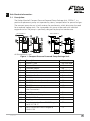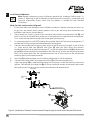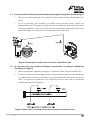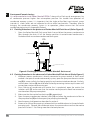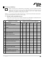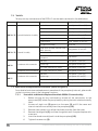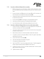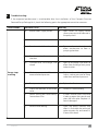
1
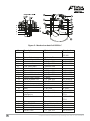
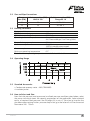
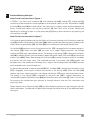
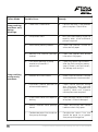
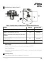
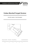
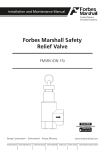
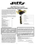
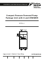
Installation and Maintenance Manual
Compact Pressure Powered Pump
Package Unit with IJ and CRM485R
PPPPU-C
Forbes Marshall
Forbes Marshall Arca
Codel International
Krohne Marshall
Forbes Solar
Forbes Vyncke
Forbes Marshall Steam Systems
Table of Contents
1.
Preface ................................................................................1
2.
Important Safety Notes ........................................................1
3.
Brief Product Information .....................................................3
4.
Product Working Principle ...................................................7
5.
Installation Guidelines .........................................................8
6.
Startup and Commissioning ................................................10
7.
Maintenance Guidelines .....................................................11
8.
Troubleshooting .................................................................15
9.
Available Spares ................................................................17
10.
Warranty Period .................................................................17
PLEASE NOTE - Throughout this manual this cautionary symbol is used to
describe a potential damage or injury that might occur if the safety
considerations are overlooked. This symbol denotes CAUTION, WARNING or
DANGER.
Compact Pressure Powered Pump Package Unit with IJ and CRM485R
1.
Preface:
This manual is intended for anyone using, commissioning, servicing, or disposing the below
mentioned products safely and efficiently.
1.
Compact Pressure Powered Pump Package Unit with IJ and CRM485R [PPPPU-C]
Size: DN20 (3/4'') , DN25 (1'')
PLEASE NOTE
Throughout this manual the following cautionary symbol is used to describe a potential damage
or injury that might occur if the safety considerations are overlooked.
2.
Important Safety Notes:
Read this section carefully before installing/operating/maintaining the product. The
precautions listed in this manual are provided for personnel and equipment safety.
Furthermore, Forbes Marshall accepts no responsibility for accidents or damage
occurring as a result of failure to observe these precautions. Note that the product is
designed to perform for non-contaminated fluids only. A contamination in the form of
chemical, foreign particle etc. can lead to problem with product performance and life of
the product.
If these products in compliance with the operating instructions are, properly installed,
commissioned, maintained and installed by qualified personnel (refer Section 2.7) the safety
operations of these products can be guaranteed. General instructions for proper use of tools and
safety of equipments, pipeline and plant construction must also be complied with.
2.1 Intended use:
Check if the product is suitable for intended use/ application by referring to the installation
and maintenance instructions, name plates and technical information sheets.
i)
The product is suitable for use as defined in the technical information sheet. In case the
need arises to use the product on any other fluid please contact Forbes Marshall for
assistance.
ii) Check for the suitability in conformance to the limiting conditions specified in technical
information sheet of the product.
iii) The correct installation and direction of fluid flow has to be determined.
iv) Forbes Marshall products are not intended to resist external stresses, hence necessary
precautions to be taken to minimize the same.
2.2 Accessibility and Lighting:
Safe accessibility and working conditions are to be ensured prior to working on the product.
2.3 Hazardous environment and media:
The product has to be protected from hazardous environment and check to ensure that no
hazardous liquids or gases pass through the product.
PPPPU-C
1
2.4 Depressurizing of systems and normalizing of temperature:
Ensure isolation and safety venting of any pressure to the atmospheric pressure. Even if the
pressure gauge indicates zero, do not make an assumption that the system has been
depressurized.
To avoid danger of burns allow temperature to normalize after isolation.
2.5 Tools and consumables:
Ensure you have appropriate tools and / or consumables available before starting the work.
Use of original Forbes Marshall replacement parts is recommended.
2.6 Protective clothing:
Consider for the requirement of any protective clothing for you/ or others in the vicinity for
protection against hazards of temperature (high or low), chemicals, radiation, dangers to
eyes and face, noise and falling objects
2.7 Permits to work:
All work to be carried out under supervision of a competent person. Training should be
imparted to operating personnel on correct usage of product as per Installation and
Maintenance instruction. “Permit to work” to be complied with (wherever applicable), in
case of absence of this system a responsible person should have complete information and
knowledge on what work is going on and where required, arrange to have an assistant with
his primary goal and responsibility being safety. “Warning Notices” should be posted
wherever necessary.
2.8 Handling:
There is a risk of injury if heavy products are handled manually. Analyze the risk and use
appropriate handling method by taking into consideration the task, individual, the working
environment and the load.
2.9 Freezing:
Provision should be made to protect systems which are not self-draining, against frost
damage (in environment where they may be exposed to temperatures below freezing point)
to be made.
2.10 Returning products:
Customers and Stockist are reminded that, when returning products to Forbes Marshall they
must provide information on any hazards and the precautions to be taken due to
contamination residues or mechanical damage which may present a health, safety or
environmental risk.
This information must be provided in writing including Health and Safety data sheets
relating to any substances identified as hazardous or potentially hazardous.
2
Compact Pressure Powered Pump Package Unit with IJ and CRM485R
3.
Brief Product Information:
3.1 Description:
The Forbes Marshall Compact Pressure Powered Pump Package Unit, PPPPU-C, is a
positive displacement pump unit operated by steam, compressed air or pressurised gas.
The compact pump has an in-built receiver for condensate, which eliminates the need
for a separate storage tank. The size enables this pump to be used with individual
equipment also. The pump is specifically designed to pump hot condensate.
DN 20 PPPPU-C
DN 25 PPPPU-C
All Dimensions in ‘mm’
Figure 1 : Compact Pressure Powered Pump Package Unit
Sr.no.
1
2
3
4
5
6
7
8
9
10
11
12
13
14
15
16
17
PPPPU-C
Description
PPPPU-C Shell
Exhaust Elbow
Overflow Socket
Reciever Shell
Condensate Inlet Line
Ball Valve For Condensate Inlet
DN20 Strainer
DN25 Check valve for condensate inlet
DN25 Check valve for condensate outlet
DN15 Drain
DN15 Piston Valve For Steam
Inlet Connection
DN15 Strainer Steam Inlet
Cover Plate Assembly
DN15 MLT21 Trap
Leg Support
Condensate Inlet Conn. DN20 Flanged
to BS 10 TAB 'E'
Vent Connection DN50 Flanged to
ANSI # 150
Material
MS ERW Pipe
MS
MS
MS ERW Pipe
MS
Carbon Steel
C.I.
S.S.
S.S.
MS
FCS
CI
CI
SS
MS
CS
CS
3
Figure 2 : Mechanism detail of PPPPU-C
4
Sr.no. Description
1
Cover
Material
Cast iron
2
3
4
5
6
7
8
9(a)
9(b)
10
11
12
13
14
15
16
17
Synthetic Fibre
Cast steel
S.S. Type 304
S.S. Type 304
Stainless steel
Copper
S.S. Type 304
S.S. Type 304
S.S. Type 304
Copper
S.S. Type 304
S.S. Type 304
Cast iron
Stainless steel
Cast steel
S.S. Type 304
Stainless steel
18
Cover Gasket
Stud and Nut M·12
Inlet Valve Seat
Inlet Valve Stem
Inlet Valve Head
Inlet Seat Gasket
Exhaust Valve
Exhaust Valve
Exhaust Valve Head
Exhaust Seat Gasket
Valve Actuator Disc
Push Rod
Mechanism
Mechanism Studs M12
Body
Float
Linage
Mechanism
Push Rod Actuator
Stainless steel
19
20
21
22
23
Spring
Plug 1/2”BSPT
Check Valve
Flow-temp Sensor
Sensor Float
Inconel
Forged Carbon Steel
Stainless steel
Stainless steel
S.S. Type 304
Standard
IS 210 Gr
FG 260
ASTM A276
ASTM A276
ASTM A276
ASTM A276
ASTM A276
ASTM A276
ASTM A240
IS 210 FG 260
IS 1364
IS 2062
ASTM A240
ASTM A351
CF 8
ASTM A351
CF 8
ASTM A105
ASTM A240
Compact Pressure Powered Pump Package Unit with IJ and CRM485R
3.2 Size and Pipe Connections
Pump
Size (DN)
Inlet connection (DN)
ANSI # 150
Outlet connection (DN)
Flange BS 10
20
20
20 Tab ‘H’
25
25
40 Tab ‘E’
3.3 Limiting Conditions
Design conditions
PMA Maximum design pressure
TMA Maximum design temperature
Operating inlet motive pressure
8.7 bar g
220°C
Steam / Compressed
Air / Pressurised gas 3 to 7 bar g (Max)
Pump discharge per cycle
30 Kg
Steam consumption
3 Kg of steam per
1000 Kg condensate pumped
Air consumption
22 SCF per 1000 Kg condensate pumped
Minimum operating temperature
0°C
Note: For lower operating temperatures consult Forbes Marshall
3.4 Operating Range
3.5 Standard Accessories
• Condensate recovery meter - 485 (CRM485R)
• Insulation jacket
3.6 How to Select and Size:
From the inlet pressure (motive pressure) and back pressure conditions given below, select
the pump size which meets the capacity requirement of the application. Select optional
extras, as required. Back pressure is the lift height (H) in mtr x 0.1 plus bar (g) in return line
plus downstream piping friction pressure drop in bar (g) at the lesser of six times the actual
flow rate or 340 lit/min.
PPPPU-C
5
3.7 Capacity kg/hr:
For liquid specific gravity (0.9 to 1)
No.
1
2
3
4
5
6
7
8
9
10
11
12
13
14
15
16
17
18
INLET Pr.
TOTAL Lift
(M.P.) (bar g) Or Back Pr. (bar g)
8.7
8.7
8.7
8.7
7
7
7
7
6
6
6
6
5
5
5
4
4
3
1
2
3
4
1
2
3
4
1
2
3
4
1
2
3
1
2
1
Condensate Flow Rate (Kg/hr.)
DN20
Compact Pump kg/hr
600
514
482
470
590
550
475
390
580
520
425
300
550
430
320
440
340
325
3.8 Example:
Condensate load
Steam / air pressure available for
Operating pump
Vertical lift from pump to the return piping
Pressure in return piping
(piping friction negligible)
DN25
Compact Pump kg/hr
1020
900
800
780
900
900
800
780
900
900
800
690
900
840
720
840
720
660
= 450 kg/hr
= 7 bar g
=9m
= 1.72 bar g
Solution:
1. Calculate “H”, the total lift or back pressure against which the condensate must be
pumped
= (9m x 0.1) + 1.72 = 2.62
2. From capacity table : 7 bar g operating inlet pressure and 3 bar g back pressure pump
has a capacity of 475 kg/hr.
Note from capacity factor charts:
Pump capacity using compressed air
(% BP / MP = 3/7) = 42%
= 1.1 X 475 = 522 kg/hr
3.9 Capacity multiplying factors for motive gas supplies (other than steam)
6
Compact Pressure Powered Pump Package Unit with IJ and CRM485R
4.
Product Working Principle :
Note: For this section refer to Figure 1
A PPPPU-C unit consists of a receiver (4), Inlet Isolation valve (6), Strainer (7), a body shell (1)
containing a float mechanism which operates a set of motive steam / air inlet and exhaust line (2)
and inlet (8) & outlet (9) disc check valves. The steam or air is used as motive media to operate the
pump. Condensate comes into the pump receiver (4) from Flash vessel or plant condensate
header and is allowed to flow in to the pump body (1) having float mechanism by opening the
inlet isolation valve (6).
Note: For this section refer to Figure 2
In the normal position before startup the float is at the lowest position with the motive steam/air
valve (5) closed and the exhaust valve open (9A). When condensate flows by gravity through inlet
check valve in to pump body (15), the float (16) will rise along with the level of condensate.
As the float (16) continues to rise, the mechanism link (17) is engaged which increases tension in
the springs (19). When the float (16) has risen to its upper tripping position, the linkage
mechanism (17) snaps upward over center. The energy in the springs (19) is released as the push
rod (18) is moved upward, to simultaneously open the motive steam inlet valve (5) and close the
exhaust valve (9A). Steam flow through the inlet valve (5) increases the pressure within the body
and closes the inlet check valve. The increased pressure in the body shell (15) exceeds the
backpressure in the condensate discharge line, it opens the discharge check valve (21) to pump
out the condensate in the discharge line.
As the condensate level in the pump body (15) falls, the float (16) is lowered and mechanism link
(17) is engaged, which again increases the tension in the springs (19). When the float (16)
reaches the lower tripping position, the linkage mechanism (17) snaps downward over center.
The energy in the springs (19) is released as the push rod (18) is moved downward, to
simultaneously open the exhaust valve (9A) and close the steam inlet valve (5). Steam / air utilized
for pumping the condensate gets released to through exhaust valve and this completes one
pumping stroke.
When the pressure in the pump body (15) has fallen below the pressure in the inlet pipe, the inlet
check valve opens. Condensate will again flow through the check valve to fill the body and begin
next cycle.
PPPPU-C
7
5.
Installation Guidelines :
Note: Before implementing any installations observe the 'Important Safety notes” in
section 2. Referring to the Installation and Maintenance Instructions, name-plate and
Technical Information Sheet, check that the product is suitable for the intended
installation.
Note: For this section refer to Figure 3
1.
2.
3.
4.
5.
6.
7.
Ensure that there is no damage in transit. Before installation is done ensure that all steam, air
or gas lines are closed. Select correct pipeline sizes as per the pump and connections are
available. Level the unit by level bottle.
The reservoir has 3 ports, two of them should be connected for condensate inlet (A) and
third is used for vent line ©. Most important is that reservoir must be vented to atmosphere.
This is to ensure free flow of condensate under gravity to the pump.
It is recommended to install PPPPU along with a Forbes Marshall Flash vessel arrangement, if
condensate flashing is expected when exposed to atmosphere.
Connect the condensate line coming from plant to the flash vessel inlet port. Install strainer
(1), single orifice float trap (2) and view glass (3) after the flash vessel and connect
condensate outlet line to the pump receiver (6). Install the safety relief valve (4) and pressure
gauge (5) at respective locations provided on the flash vessel. Ensure that the pump receiver
inlet is at a lower level than the condensate outlet line of flash vessel so the condensate
travels by gravity to the pump receiver.
Vent line (C) should be piped, unrestricted to safe location in the atmosphere.
Connect the motive steam or compressed airline (7) to the motive supply inlet .
A pressure gauge (8) is supplied loose along with the pump. Install the same on motive line
syphon. Condensate discharge line (B) of pump should be routed to the boiler feed water
tank and connect the same to the condensate nozzle of de-aerator head.
Flash Steam
4
5
Condensate
Inlet
2
1
3
Condensate Line
A
C
A
B
Figure 3: Installation of Compact Pressure Powered Pump Package Unit with Forbes Marshall Flash Vessel
8
Compact Pressure Powered Pump Package Unit with IJ and CRM485R
5.1 Care to be taken while routing the condensate pump discharge line :(Refer to Fig.4)
i.
The line size should be equal to or more than pump outlet flange size provided with
pump.
ii.
As far as possible, the discharge line should have minimum bends. Ideally the
condensate pump discharge line should be lifted immediately after the pump to the
maximum elevation in the circuit and then to be connected to feed water tank with a
downward slope. This ensures minimum backpressure on the pump.
Figure 4: Routing the condensate line to the Feed Water Tank
5.2 In case more than one condensate pump is connected to a common Condensate
line: (Refer to Figure 5)
1.
Make sure that NRV supplied with pump is installed with flow direction towards FWT.
2.
If more than one-pump discharge lines are to be connected to a common condensate
line, please ensure that the individual line is connected from the top with a non-return
valve. The common condensate line should be sized to take care of connected
condensate load of all the pumps.
Figure 5: More than one pump connected to common condensate line
PPPPU-C
9
6.
Startup and Commissioning :
It is recommended to install Forbes Marshall PPPPU-C along with a Flash vessel arrangement, for
all condensate pressure higher than atmosphere pressure. For trouble free operation of
condensate recovery system, it is important that the single orifice float trap internals, pump
internals & check valves are not subjected to dirt or other hard particles. Therefore, prior to
bringing the condensate recovery system in to operation, please ensure that the entire
condensate piping circuit is thoroughly flushed.
6.1 Flushing Procedure in the presence of Forbes Marshall Flash Vessel : (Refer Figure 6)
1. Open the Forbes Marshall Flash vessel drain line and allow the process condensate to
flow through the drain till all the foreign particles & contaminated condensate is
flushed out and we see clean condensate coming out.
Flash
Steam
Outlet
Condensate Intlet
Condensate Outlet
Drain
Line
Figure 6: Flushing procedure of Forbes Marshall flash vessel
6.2 Flushing Procedure in the absence of a Forbes Marshall Flash Vessel: (Refer Figure 1)
1. Wherever process condensate is directly connected to pump receiver & Flash vessel
module is not part of condensate recovery system, open the pump condensate strainer
cap (5) & screen to flush the foreign particles and contaminated condensate. Similarly,
motive steam / airline (4) should also be flushed by removing strainer cap & screen until
we see clean motive media coming out.
2. Once flushing of condensate and motive line is completed, open the motive line
isolation valve (7) and ensure that the motive media pressure should not exceed as
mentioned on the pump nameplate.
3. Make sure that the motive line drain trap (8) is operational.
4. Open the pump condensate isolation valve (11) and allow the condensate to flow to
the pump receiver (2) and subsequently to pumping chamber (1).
5. Now the pump shall operate as described in section 4.
6. Steam or air utilized for pumping is released with an audible exhaust at the end of each
pumping cycle. Observe the condensate return line pressure & ensure that the motive
pressure is at least 1.5 to 2 bar g more than the back pressure.
10
Compact Pressure Powered Pump Package Unit with IJ and CRM485R
7.
Maintenance Guidelines :
Before undertaking any maintenance on the product it must be isolated from both
supply line and return line and any pressure should be allowed to safely normalize to
atmosphere. The product should then be allowed to cool. With suitable isolation
repairs can be carried out with the product in the line.
PPPPU-C units are designed for trouble free operation. In normal course of action maintenance is
not required provided certain care of the system is taken.
7.1 Routine and Preventive Maintenance:
Please refer to the maintenance schedule mentioned in the table below to undertake routine
maintenance of the Compact Pressure Powered Pump Package Unit.
QP,
NO.
A
PARAMETERS TO BE CHECKED
Compact Pressure Powered Pump Package
Unit/Flash Vessel
FREQUENCY FOR CHECKING VARIOUS PARAMETERS
Daily
Weekly
Monthly
Quarterly
1
Clean strainer of motive media line
Y
2
Clean condensate inlet strainer
Y
3
Visual inspection and cleaning of complete set of
internals
Y
4
Condensate pump chamber draining
Y
5
Inlet / Exhaust valve leakage testing
Y
6
Check Valve Cleaning
7
Operate motive line valve
Y
8
Operate Condensate inlet valve
Y
9
Lubrication of piston valves
10
Pr. Gauge calibration
11
Checking of PPPPU-C motive pressure
Y
12
Checking of flash steam pressure in flash vessel
Y
13
Cleaning of motive line trap internals
14
Cleaning of flash vessel steam trap internals
15
Visual inspection for leakages
Y
16
Arresting any other leaks
Y
17
Checking of float trap SLR setting
18
Cleaning of strainer between flash vessel and
pump
19
Check air quality(in case motive media is air)
Y
20
Visual inspection of safety relief valve
Y
21
Overhauling and cleaning of safety relief valve
PPPPU-C
Half
Yearly
Annually.
Y
Y
Y
Y
Y
Y
Y
Y
11
7.2 Tool Kit:
To carry out any maintenance of the PPPPU-C use the tools mentioned in the table below
Size
Part
DN 20 / 25 Internal Mechanism Assembly
DN 20 / 25 External Assembly
DN 20
Condensate inlet connection
Condensate return connection
DN 25
Condensate inlet connection
Condensate return connection
Component
Tool used and Size
Motive inlet and exhaust Valve
Open Spanner 26 mm (A/F)
Float Mechanism
Open Spanner 19 mm (A/F)
Push Rod and Lock Nut
Open Spanner 17 mm (A/F)
Bush assembly and stop bolt
Box Spanner 13 mm (A/F)
Stopper bracket bolt
Box spanner 8 mm (A/F)
Float Arm Bolt
Open Spanner 10 mm (A/F)
For Split Pin Assembly
Nose Plier
Read switch assembly 4 No M6 studs;
M6 X 4mm nuts
Ring spanner 10 mm (A/F)
Internal assembly cover (M12 X 50)
Open spanner 18 / 19 mm (A/F)
Motive inlet and exhaust hose pipe
connection
Pipe wrench
Ball valve
Box spanner 13 mm (A/F)
Strainer cap
Box spanner 26 mm (A/F)
Disc check valve (M16 X 75mm)
Box spanner 24 mm (A/F)
Disc check valve (M16 X 75mm)
Box spanner 24 mm (A/F)
Ball valve
Box spanner 13 mm (A/F)
Strainer cap
Box spanner 26 mm(A/F)
Disc check valve (M16 X 75mm)
Box spanner 24 mm (A/F)
Disc check valve (M16 X 75mm)
Box spanner 24 mm (A/F)
7.3 Maintenance/Replacement Procedure : (Refer to Figure 2)
For a detailed maintenance/replacement procedure of the pump body internals, please refer
to the instructions given in the subsequent sections;
7.3.1
Procedure to Maintain/Replace the whole PPPPU-C internal asbly.:
1.
Before carrying out any maintenance, remove all the connections to the
pump cover (1). Isolate the pump body by closing the inlet isolation butterfly
valve.
2.
Unscrew all eight nuts (3) present on the cover (1) and lift the cover and
internal mechanism assembly from the pump body (15).
3.
Remove the assembly nuts to free the whole assembly from the cover.
4.
Remove the old gasket (2), and clean the gasket area. If required replace with
a new one.
5.
Insert the whole assembly back inside the pump body (15).
6.
Tighten the cover nuts (3).
12
Compact Pressure Powered Pump Package Unit with IJ and CRM485R
7.3.2
Procedure to Maintain/Replace float assembly:
1.
Before carrying out any maintenance, remove all the connections to the
pump cover (1). Isolate the pump body by closing the inlet isolation butterfly
valve.
2.
Unscrew all eight nuts (3) present on the cover (1) and lift the cover and
internal mechanism assembly from the pump body (15).
3.
Arrange the whole assembly onto the vice such that the internals are placed
on top and clamp the cover.
7.3.3
4.
Unscrew the float (16) from the float arm using appropriate spanner.
5.
Screw the new float using Loctite 272 adhesive onto the threads.
6.
Insert the whole assembly inside the pump body and screw the nuts.
Procedure to Maintain/Replace Exhaust valve seat & head assembly:
1.
Unscrew all eight nuts (3) present on the cover (1) and lift the cover and
mechanism assembly from the pump body (15).
2.
Arrange the whole assembly onto the vice such that the internals are placed
on top and clamp the cover.
3.
Remove the assembly nuts to free the whole assembly from the cover.
4.
If required, remove the old gasket (2), and clean the gasket area before
replacing with a new one.
5.
Unscrew the Exhaust valve head (9B).
6.
Clean the metal gasket and replace if required.
7.
Fit the exhaust valve head and seat.
8.
Now fit the PPPPU-C internal assembly onto the cover. Carefully engage the
exhaust valve onto the actuator disc (11) and screw the nuts.
9.
Unclamp the cover and insert the whole assembly back inside the pump
body. While reinstalling the cover.
10. Tighten the cover nuts (3).
PPPPU-C
13
7.3.4
Procedure to Maintain/Replace Inlet valve seat and head assembly:
1.
Follow steps 1 through to 4 of section 7.3.3
2.
Unscrew the Inlet valve head (6).
3.
Clean the metal gasket and replace if required.
4.
Fit the inlet valve head and seat.
5.
Now fit the PPPPU-C internal assembly onto the cover (1). Carefully engage
the exhaust valve (9A) onto the actuator disc (11) and screw the nuts.
6.
Unclamp the cover and insert the whole assembly back inside the pump body
(15). While reinstalling the cover.
7.
7.3.5
14
Tighten the cover nuts (3).
Procedure to Maintain/Replace the springs:
1. Unscrew all eight nuts (3) present on the cover (1) and lift the cover and
mechanism assembly from the pump body (15).
2. Arrange the whole assembly onto the vice such that the internals are placed
on top and clamp the cover.
3. Remove the split pins.
4. Remove the washer and the springs (19) from the linkage mechanism (17)
5. Clean the springs (19) and replace if required.
6. Put the washer and split pins back
7. Insert the whole assembly back inside the pump body (15).
8. Tighten the cover nuts (3).
Compact Pressure Powered Pump Package Unit with IJ and CRM485R
8.
Troubleshooting:
If the expected performance is unachievable after the installation of the Compact Pressure
Powered Pump Package Unit, check the following points for appropriate corrective measures.
Failure Mode
Pump stops
working
PPPPU-C
Possible Cause
Remedy
a)
Motive steam supply closed.
a)
Open valves to supply motive
steam pressure to condensate in
the pump shell.
b)
Motive line strainer chocked.
b)
Clean the strainer.
c)
Condensate inlet line closed.
c)
Open condensate inlet valve and
allow condensate to flow in
pumping chamber.
d)
C o n d e n s a t e l i n e s t r a i n e r d)
chocked
Clean the strainer.
e)
Condensate discharge line e)
closed
Open all discharge line valves to
allow free discharge from pump
to destination.
f)
Motive pressure insufficient to f)
overcome back pressure
Check motive and back pressure.
Adjust motive pressure to 2barg
more than total back pressure.
g)
Float punctured
Replace the float.
h)
Check the direction of the check h)
valve
Correct it if found wrong.
i)
Steam coming out continuously i)
from exhaust line
It means motive steam inlet valve
is leaking- open the internals and
clean the inlet valve. Replace it if
found damaged.
j)
Exhaust valve leaking
Open the pump internals and
clean it. Also check the setting of
valve actuator disc and correct it
if found disturbed.
g)
j)
15
Failure Mode
Pump working,
overflows only
during
discharge.
Pump working,
continuously
overflows
16
Possible Cause
Remedy
a)
Check inlet Check Valve
a)
Lap the seat and if the problem
persists replace Check Valve
a)
Pump under sized.
a)
Verify the rated capacity as per the
capacity table. Install additional
pump as required.
b)
Inlet strainer partially choked
b)
Clean the strainer. Ensure all
valves are fully open.
c)
Motive line strainer partially c)
choked.
Clean the strainer and ensure
inlet valve is fully open.
d)
Live steam reaching in pump
receiver and receiver is
pressurized.
d)
Check the steam trap installed
after the Flash vessel or process
traps (if there is no Flash vessel),
for leakage and rectify it.
e)
Receiver vent line is closed.
e)
Make sure that receiver is vented
to atmosphere as recommended.
f)
Insufficient motive pressure to f)
achieve rated capacity.
Check motive pressure setting
and maximum back pressure
during operation. Compare with
capacity table and increase
motive pressure as required.
g)
Outlet check valve stuck open or g)
leaking
Open the check valve and clean it
or replace it if found damaged.
h)
Motive isolation valve partially h)
closed.
Check and ensure that motive
isolation valve is fully open.
i)
Condensate return line size lesser i)
than pump discharge.
Condensate return line size
should be equal to or greater
than pump discharge line.
Compact Pressure Powered Pump Package Unit with IJ and CRM485R
9.
Available Spares : (Refer to Figure 7 )
Figure 7: Available Spares of Compact Pressure Powered Pump Package Unit
SPARES
PART NO.
SPARE CODES
11
S2001086
1,2,3
S2001087
SPARE KIT FOR PPPPU-C INLET VALVE SEAT AND HEAD
ASSEMBLY
4,5
S2001088
SPARE KIT FOR PPPPU-C EXHAUST VALVE SEAT AND
HEAD ASSEMBLY
6,7
S2001089
FLOAT ASSEMBLY
8
S2001030
SPARE KIT FOR PPPPU-C SPRING ASSEMBLY(SET OF 2)
9
S2001046
SPARE KIT FOR PPPPU-C INTERNALS
SPARE KIT FOR GASKET SET (SET OF 5)
How to Order:
Example : DN 20 Compact Pressure Powered Pump Package Unit PPPPU-C
How to Order Spares:
Always order spares giving description and P.C. No. given in ‘User Manual’ under the heading
“Available spares”.
10.
Warranty Period:
As per the ordering information and agreement in the contract
PPPPU-C
17
Forbes Marshall
B-85, Phase II, Chakan Indl Area
Systems Pvt. Ltd.
Sawardari, Chakan
(Formerly Spirax Marshall Pvt. Ltd.)
Tal. Khed, Dist. Pune 410501. INDIA. Opp 106th Milestone
Tel : +91 02135 393400
Email : [email protected]
Forbes Marshall Steam
Bombay Poona Road, Kasarwadi,
Pune 411 034. INDIA.
Tel.: 91(0)20-27145595, 39858555
CIN No : U27109PN1959PTC011334
www.forbesmarshall.com
Doc# FMSS/0415/UM-PPPPU-C/V1.R0
ALL CONTENTS HEREIN ARE THE PROPERTY OF FORBES MARSHALL PRIVATE LIMITED (“FMPL”) OR FORBES MARSHALL STEAM SYSTEMS PRIVATE
LIMITED (“FMSSPL”), AS THE CASE MAY BE, AND HAVING PROTECTION UNDER THE INTELLECTUAL PROPERTY RIGHTS. ANY REPRODUCTION,
DISTRIBUTION OR DISCLOSURE WITHOUT PRIOR WRITTEN PERMISSION IS PROHIBITED.
The information in this document is subject to change without notice. FMPL or its Subsidiaries, Associates, Affiliates and Group Companies assume no
responsibility for inaccuracies or omissions and specifically disclaim any liabilities, losses, or risks, personal or otherwise, incurred as a consequence,
directly or indirectly, of the use or application of any of the contents of this document.