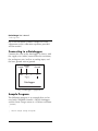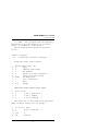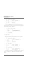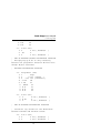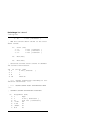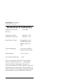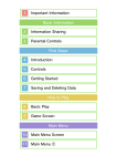
1
Drain Gauge
Gee Passive Capillary Lysimeter
User’s Manual
Version 1.0
Decagon Devices, Inc.
©2003 Decagon Devices, Inc.
All rights reserved.
950 NE Nelson Court
Pullman WA 99163
USA
Drain Gauge User’s Manual
Table of Contents
Contents
1. Introduction . . . . . . . . . . . . . . . . . . . . . . . . . . . . . 1
Welcome . . . . . . . . . . . . . . . . . . . . . . . . . . . . . . . 1
Drain Gauge Specifications . . . . . . . . . . . . . . . 1
Contact Information . . . . . . . . . . . . . . . . . . . . . . 1
Warranty Information . . . . . . . . . . . . . . . . . . . . 1
Seller’s Liability . . . . . . . . . . . . . . . . . . . . . . . . . . 2
2. The Drain Gauge . . . . . . . . . . . . . . . . . . . . . . . 3
About the Drain Gauge . . . . . . . . . . . . . . . . . . . 3
How it Works: . . . . . . . . . . . . . . . . . . . . . . . . . . . 3
Features . . . . . . . . . . . . . . . . . . . . . . . . . . . . . . . . 4
Wiring Diagrams . . . . . . . . . . . . . . . . . . . . . . . . . 5
Extension cables . . . . . . . . . . . . . . . . . . . . . . . . . 6
General Theory and
Considerations . . . . . . . . . . . . . . . . . . . . . . . . . . . . . . 6
3. Installing the Drain Gauge . . . . . . . . . . . . . 10
Location Preparation . . . . . . . . . . . . . . . . . . . . 10
Excavation . . . . . . . . . . . . . . . . . . . . . . . . . . . . . . 11
Installation - Wick Section . . . . . . . . . . . . . . . 12
Installation - Divergence Tube . . . . . . . . . . . . 13
Installation-Valve Box . . . . . . . . . . . . . . . . . . . 14
Calibration and Testing . . . . . . . . . . . . . . . . . . 15
Troubleshooting . . . . . . . . . . . . . . . . . . . . . . . . 15
Data Analysis . . . . . . . . . . . . . . . . . . . . . . . . . . . 16
Calculating Drainage . . . . . . . . . . . . . . . . . . . . 16
Solution Sampling . . . . . . . . . . . . . . . . . . . . . . . 17
Monitoring and Equilibration . . . . . . . . . . . . . 17
Water Balance . . . . . . . . . . . . . . . . . . . . . . . . . 17
References . . . . . . . . . . . . . . . . . . . . . . . . . . . . . 18
i
Drain Gauge User’s Manual
Table of Contents
4. Collecting Data . . . . . . . . . . . . . . . . . . . . . . . . 19
Datalogger Requirements . . . . . . . . . . . . . . . . 19
Connecting to a Datalogger . . . . . . . . . . . . . .20
Sample Program . . . . . . . . . . . . . . . . . . . . . . . .20
Troubleshooting . . . . . . . . . . . . . . . . . . . . . . . . 29
Declaration of Conformity . . . . . . . . . . . . . . .30
ii
Drain Gauge User’s Manual
Introduction
1. Introduction
Welcome
Thank you for purchasing the Drain Gauge. This
innovative instrument will enable you to monitor
soil water movement and chemical leaching accurately and affordably.
Drain Gauge Specifications
Total height: 150cm
Top opening width: 20cm
Length of divergence control zone: 66cm
Length of pipe: 81cm
Drain diameter: 4.2cm
Connector type: 3.5 mm plug
Datalogger Compatibility (not exclusive):
• Decagon Em5, Em5R
• CSI: CR10, CR10X, 21X, 23X, CR7, CR200 Family
Contact Information
• Email: [email protected]
• Fax: (509) 332-5158
• Phone: 1-800-755-2751 (US and Canada only)
or 509-332-2756.
Warranty Information
The Drain Gauge has a 30-day satisfaction guarantee and a one-year warranty.
1
Drain Gauge User’s Manual
Introduction
Seller’s Liability
Seller warrants new equipment of its own manufacture against defective workmanship and materials
for a period of one year from date of receipt of
equipment (the results of ordinary wear and tear,
neglect, misuse, accident and excessive deterioration due to corrosion from any cause are not to be
considered a defect); but Seller’s liability for defective parts shall in no event exceed the furnishing of
replacement parts F.O.B. the factory where originally manufactured. Material and equipment covered hereby which is not manufactured by Seller
shall be covered only by the warranty of its manufacturer. Seller shall not be liable to Buyer for loss,
damage or injuries to persons (including death), or
to property or things of whatsoever kind (including,
but not without limitation, loss of anticipated profits), occasioned by or arising out of the installation,
operation, use, misuse, nonuse, repair, or replacement of said material and equipment, or out of the
use of any method or process for which the same
may be employed. The use of this equipment constitutes Buyer’s acceptance of the terms set forth in
this warranty. There are no understandings, representations, or warranties of any kind, express,
implied, statutory or otherwise (including, but without limitation, the implied warranties of merchantability and fitness for a particular purpose), not
expressly set forth herein.
2
Drain Gauge User’s Manual
The Drain Gauge
2. The Drain Gauge
About the Drain Gauge
The Drain Gauge is designed to be installed in the
ground for long-term monitoring, with an estimated
minimum 10-year lifetime. The Drain Gauge also
has a collection system that allows for rapid sampling of drainage waters.
How it Works:
1. The Drain Gauge is installed below the root
zone.
2. Water infiltrates down through the divergence
control tube, and then down a speciallydesigned fiberglass wick into a collector.
3. The water fills the height of the collector, and
the water level is monitored by a an electronic
water level gauge.
4. A sampling syringe, attached to the water reservoir sampling port, can draw water samples out
for chemical analysis.
5. When the water level reaches the top of the
siphon tube, the water empties and the change
in water volume is recorded by an attached
datalogger. The emptied water drains out the
end of the apparatus and back into the soil.
3
Drain Gauge User’s Manual
The Drain Gauge
Features
Em5
Sampling Syringe
Divergence
Control Tube
(Removable)
Sheath
Wick
Siphon
Water Level
Gauge
Water Reservoir
Sampling Port
Drain
Fig.1: Drain Gauge probe diagram
4
Drain Gauge User’s Manual
The Drain Gauge
Wiring Diagrams
3.5mm plug wiring
The Drain Gauge’s moisture sensor comes with a
3.5mm “stereo-plug” style connector. This allows for
rapid connection directly to Decagon’s Em5 data
logger. Below is a diagram showing the wiring configuration for this connector.
Analog
out
Ground
Excitation
Fig. 2: Sensor plug wiring configuration
Adapter cable wiring
The sensor adapter cable for connection to nonDecagon equipment contains 3 wires as shown
below. The cable plug has integrated inductors
designed to provide signal noise reduction.
Analog out (Red)
Ground (Bare)
Adapter cable
Excitation (White)
Fig. 3: Adapter cable wiring configuration
5
Drain Gauge User’s Manual
The Drain Gauge
NOTE!: Be aware that cutting off the cable plug
or cutting the cable in any other way will void
your warranty, since the plug and cable are
both specially engineered for optimal performance and noise reduction.
Extension cables
Decagon supplies 50-foot (15.25m) and 10-foot
(3m) extension cables to attach to the sensor cable.
You can safely connect up to 3 of the 50-foot cables
without signal attenuation. For most applications,
you will want to seal the connections from the elements to maintain a good connection and to prevent corrosion. Decagon provides heat-shrink with
all extension cables upon request. To seal a connection between two extension cables using the heatshrink, simply ensure that the heatshrink is covering
the connection, then heat it using a heat-gun, blowdryer or a lighter until it shrinks tight to the connection. Note: If using a lighter, place the heatshrink well above the flame to avoid melting
the heat shrink and the connector.
General Theory and
Considerations
A soil water balance takes into consideration the
inputs, losses and storage of water in a soil profile.
An important component of the water balance is the
water that drains from the bottom of the soil profile,
often referred to as "deep drainage" or "deep percolation." This is water that has gone sufficiently far
below the root zone that it cannot be removed from
6
Drain Gauge User’s Manual
The Drain Gauge
the soil by transpiration or evaporation. The other
components of the water balance can be measured,
but the deep drainage typically has been computed
as the remainder when the other components were
measured and accounted for. Because of uncertainties in the measurements of the other water balance
components, deep drainage estimates were subject
to large errors.
The Drain Gauge now allows direct measurement of
the deep drainage component of the water balance.
This is accomplished by intercepting and collecting
the water that moves below the root zone. The
Drain Gauge is sometimes referred to as a passive
wick lysimeter. It has a specially treated fiberglass
wick which maintains a tension on the water at the
bottom of the soil profile from which it is extracting
water. Without this tension, water would "pile up"
at the outflow boundary, and force the water in the
soil above to move around the Drain Gage, rather
than into it. The divergence control tube on the top
of the Drain Gage is also for the purpose of maintaining vertical flow above the Gauge so that the
Drain Gage intercepts a representative sample.
Both the amount of sample and its chemical composition need to be representative of deep drainage in
the area in which the drain gage is installed.
Whether or not this is true is determined largely by
the installation. The main issues are:
1. Depth of installation
2. Soil disturbance above the Drain Gauge.
7
Drain Gauge User’s Manual
The Drain Gauge
3. Contact between the wick and the soil profile.
Following are some general comments related to
these issues. Specific installation procedures are
then outlined in the next chapter.
Depth of Installation
In any soil profile, there is a zone of recharge and
seasonal depletion extending to the bottom of the
root zone. Since root density decreases with depth,
the bottom of this zone may be difficult to locate. In
annual crops it is typically around 1 m, but can be
much deeper in perennials. There is, of course, a
practical limit to how deep the Drain Gauge can be
installed. With shallow-rooted crops this is not an
issue, but with deep-rooted plants, one may need to
strike a compromise between getting below all
roots and installing the Gauge at a practical depth.
Even when roots go quite deep, the amount of
water taken up by these roots may be quite small.
Another consideration is the depth of the water
table. The water table depth must always be below
the bottom of the Drain Gauge so that water can
drain out. This might sometimes require that the
Drain Gauge be installed at a shallower depth than
would be ideal to accommodate the root zone.
The consequence of installing the Drain Gauge at
too deep a depth is that it will require a long time to
come to steady state and give drainage numbers
that are representative. The consequence of installing it at too shallow a depth is an over-estimation of
8
Drain Gauge User’s Manual
The Drain Gauge
deep drainage because some water that would have
been transpired is intercepted and drained away. It
is also possible that roots could grow down the
wick and use water from, or clog the Drain Gauge.
Soil Disturbance
It is impossible to install the Drain Gauge without
disturbing the soil. The goal is to install it in such a
way that the disturbance has minimal impact on the
Gauge's ability to measure deep drainage. The three
factors that will affect deep drainage are: changes in
root uptake patterns, changes in soil moisture storage, and changes in evaporation. In some cases, it
may be necessary to install the Drain Gauge
beneath an undisturbed core of soil. In all cases it
will be necessary to allow time for roots to grow
back into disturbed soil. If the soil surface is tilled,
there is no point in trying to keep that part of the
soil undisturbed, since it is already disturbed.
Soil-Wick Contact
In order for the bottom of the soil profile to be
under tension, the tension in the wick must be
transferred to the bottom of the soil column. There
must therefore be good capillary continuity
between the soil column and the wick. If the Drain
Gauge is installed by backfilling with soil, the contact is likely to be good without further effort. If an
undisturbed core is installed, capillary continuity is
established by placing a layer of diatomaceous earth
over the wick. The diatomaceous earth conforms to
the irregularities of the soil and wick to provide
continuity.
9
Drain Gauge User’s Manual
Installing the Drain Gauge
3. Installing the Drain
Gauge
Several references on Drain Gauge installation techniques are given at the end of this section, and two
of those methods are discussed below. The one that
you should use depends on your soil type and the
purpose of your research. If your goal is to investigate an undisturbed soil core, you will need to
secure a soil monolith inside the divergence control
tube. However, if repacking the soil in layers is sufficient (and it is in many cases), you will save yourself a lot of work. Both methods are explained
below.
Location Preparation
1. Select a location for your installation (allow
plenty of room to move around the hole) and
lay a tarp nearby that can be used to hold the
vegetation and soil that will be removed from
the site.
2. Remove the surface vegetation and place it on
the tarp. Try to preserve as much of the root
mass as possible. Also, it is important to organize the vegetation you remove so that it can be
replaced as closely as possible to its original
location.
10
Drain Gauge User’s Manual
Installing the Drain Gauge
Excavation
The depth of the Divergence Control Tube (DCT)
hole depends on the depth of the root zone. The
objective of the installation is to place the middle
plate of the Drain Gauge below the root zone of the
cover vegetation. Thus, the depth of the hole will
vary between installations, but it must be at least 90
cm deep the DCT will be completely buried below
the soil surface.
There are two different methods (see above) for
installing the drain gauge, depending on whether
you use a disturbed sample (Method 1) or an intact
monolith (Method 2).
Method 1:
Digging the hole for the Drain Gauge is most effective with a sharpshooter shovel or post-hole digger
and an orchard auger with a long extension.
1. Make the initial hole (for the divergence control
tube) about 25 cm in diameter (slightly larger
than the tube itself) and at least 90 cm deep.
2. Dig another hole (7 cm diameter by 80 cm deep;
for the wick section of the drain gauge) in the
bottom-center of the DCT hole. The orchard
auger can be very effective for this portion of
the hole because of its long handle.
3. Add 4-5 cm of rock, gravel or sand to the bottom
of the wick section hole to allow water to flow
freely below the Drain Gauge.
11
Drain Gauge User’s Manual
Installing the Drain Gauge
Method 2
If you would like an undisturbed soil monolith, it
can be obtained from either the installation site or
an adjacent site. The procedure is similar for both
methods.
1. Carefully remove soil to the depth of the top of
the DCT. Note: The hole you dig must be wide
enough to allow you to easily dig around the outside of the DCT.
2. Place the DCT at the bottom-center of the hole.
Then dig down 10 to 20 cm around the outside
of the tube and pound the DCT into the soil by
placing a board on top of the tube and striking it
with a sledgehammer. Repeat this process until
the DCT is filled with soil.
3. Use a shovel to free the DCT from the surrounding soil and lay it aside. Now, dig the hole for
the wick section according to Method 1.
4. Once the hole is deep enough for both the DCT
and the wick section, add 4-5 cm of crushed
rock, gravel or sand to the bottom of the hole.
This will allow for free movement of the effluent
water from the bottom of the Drain Gauge.
Installation - Wick Section
1. Cut a slot in the top of the wick section hole so
the tubes and wire pass around the edge of the
middle plate without damage.
2. Carefully lower the wick section into the hole,
but be especially careful not to kink or break the
12
Drain Gauge User’s Manual
Installing the Drain Gauge
sensor wire and calibration and sampling tubes.
The plate should rest on the shoulder around
the wick section hole.
3. Apply a 2 cm thick layer of diatomaceous earth
(included in your Drain Gauge kit) on top of the
fiberglass fabric. The diatomaceous earth will
enhance the contact between the soil in the DCT
and the fiberglass wick.
4. After the lower section is installed, place the
fiberglass fabric sheet and diatomaceous earth
on top of the wick section to help filter the percolating water.
Installation - Divergence Tube
There are also two different methods for installing
the DCT (divergence control tube):
Method 1:
1. Lower the empty DCT on top of the plate segment of the wick section. The outer edge of the
DCT should fit on top of the outside of the plate.
2. Repack the soil you removed from the DCT
hole. Take care to repack the soil layers in the
same order that it came out and at the approximate density of the adjacent undisturbed soil.
3. Backfill and pack soil around the outside of the
DCT.
13
Drain Gauge User’s Manual
Installing the Drain Gauge
Method 2:
1. Lower the intact soil monolith onto the diatomaceous earth that was applied to the wick section.
2. Backfill and pack the soil around the outside of
the DCT.
After installing the divergence control tube, place
and pack the soil from the root zone and replace
the cover vegetation. You may want to mound additional soil on top of the drain gauge to compensate
for soil settling.
Installation-Valve Box
We recommend that you install a sprinkler valve
box next to the Drain Gauge to provide easy access
and protection to the calibration and sampling
tubes. Valve boxes are readily available from sprinkler supply stores. The valve box should be placed
far enough away from the Drain Gauge installation
so it does not interfere with the site.
1. First, dig a hole large enough to accommodate
the valve box.
2. Cut a small trench between the Drain Gauge site
and the valve box installation site (we recommend this step be completed before replacing
the surface vegetation on top of the Drain
Gauge).
3. Lay the sensor wire and calibration and sampling tubes in the trench and recover them.
14
Drain Gauge User’s Manual
Installing the Drain Gauge
4. Place the valve box into the hole and arrange
the tubes so they can be easily accessed.
Calibration and Testing
After installing the Drain Gauge, we recommend
that you test it to ensure that it is working. Although
this step can be completed at any time during the
installation process, we suggest that you do it prior
to completely burying the Drain Gauge.
The Drain Gauge comes with a calibration certificate from the factory, so calibration should not be
necessary. You can test that it is functioning by filling a 60cc syringe (included) with water and slowly
injecting it into the calibration tube. You should see
the millivolt output of the water level sensor
increase as you inject the water. At a certain level,
you should observe a tipping event after injecting
the full syringe. Please see the “Data Analysis” and
“Calculating Drainage” sections below for more calibration information.
Troubleshooting
If the probe output is not between 200 and 800 mV,
check that you have not cut the sensor wire during
installation. If you do not see a tipping event after
injecting water into the calibration tube, pull air into
the syringe and inject it into the tube. This should
push all the water out of the sampling tube and into
the reservoir.
15
Drain Gauge User’s Manual
Installing the Drain Gauge
Data Analysis
Data analysis will require your careful consideration. The Drain Gauge does not know when your
project started or what portions of time you would
like to integrate into your analysis. The Campbell
Scientific Inc. datalogger program (included in this
manual) will automatically keep track of a running
total volume through the drain gauge. The tip volume is approximately 50 cm3, but can be calculated
more accurately using the maximum and minimum
sensor readings after a tipping event (using the
instrument’s calibration data sheet). Each tip volume
is added to the total. Further, a current total is also
calculated by subtracting the current probe reading
from the minimum probe reading and adding it to
the total tip volume. Thus, you will have to reset the
accumulating volume according to your needs. Of
course, you can also write the same algorithm in a
spreadsheet program using the saved sensor output.
Some versions of Decagon's Em5 datalogger program automatically perform the same function
(check to make sure your version contains this functionality).
Calculating Drainage
Even though you have a value of percolating water
volume over time, it does not give you the actual
percolation in cm of water per time. To get this,
you must divide the total tip volume (in cm3) by the
area of the DCT (309 cm2).
16
Drain Gauge User’s Manual
Installing the Drain Gauge
Solution Sampling
The sample reservoir collects water from the water
level reservoir after each tip. Liquid can be retrieved
from the sample reservoir through the sampling
tube. Insert a 60cc syringe (included) into the sampling tube and slowly pull back on the plunger. If
liquid is present in the sampling reservoir, it should
slowly begin filling the syringe. Note: The syringe
will never completely fill with water.
Note: The liquid in the syringe will be a mix of the
all the water that has collected in the reservoir over
time. You should not assume that the composition of
the sample water is specific to a single tip event from
the reservoir.
Monitoring and Equilibration
When installation is completed, the drain gauge
needs a period of time for percolating water to
begin reaching the water level reservoir. Depending
on your application, you may want to irrigate the
Drain Gauge installation area to see that the installation is working and help speed the soil settling.
Some users keep subsurface soil moist and allowed
it to settle for a week prior to replacing the topsoil
and vegetation.
Water Balance
It is often useful to install ECHO soil moisture
probes within the divergence control tube to
observe how the water content is changing with
depth over time in the DCT. If you install ECHO
17
Drain Gauge User’s Manual
Installing the Drain Gauge
probes in the DCT, you must take care so they are
not touching any part of the DCT, as this will
adversely affect the readings. A good rule of thumb
is to locate them as close to the center of the divergence tube as possible.
References
Gee, G.W. et al., 2002. A vadose zone water fluxmeter with divergence control. Water Resources
Research, vol. 38,No. 8, 10.1029/2001 WR
000816, 2002
Installation References:
Brown K.W. et al., 1974. A procedure for placing
large undisturbed monoliths in lysimeters.
Soil Sci. Soc. Am. J. 38:981-983 .
Quinlan,P., R, Burman and e. Siemer. 1982. In Situ
lysimeter installation. ASAE Tech. Paper 822015. American Society of Agricultural Engineers, St. Joseph, MI.
http://kilburn.keene.edu/research/hydrology/RLA/
index.html#lysimeter
For more rigorous installation techniques (using
bulk density measurement etc.) Please refer to the
following websites:
http://www.soilsci.ndsu.nodak.edu/research/
soil_physics/bmp/1989/1989.html
18
Drain Gauge User’s Manual
Collecting Data
4. Collecting Data
Datalogger Requirements
The Drain Gauge’s sensor is designed to work efficiently with Decagon’s 5-channel Em5 datalogger. It
can, however, be adapted for use with other dataloggers, such as those from Campbell Scientific,
Inc., for example. The Drain Gauge sensor requires
an excitation voltage in the range of 2 to 5 volts. It
produces an output voltage that depends on the
water level surrounding the sensor, and ranges
between 10 and 35% of the excitation voltage. Any
datalogger which can produce a 2.5 to 5V excitation
with approximately 10 millisecond duration and
read a volt-level signal with 12-bit or better resolution should be compatible with the Drain Gauge
sensor. The current requirement at 2.5V is around
2mA, and at 5V it is 7-8mA.
Important Note: The Drain Gauge sensor is intended
only for use with dataloggers and readout devices
which can provide short excitation pulses. Continuous excitation not only wastes battery power, but
may, under certain circumstances, cause the sensor
to exceed government specified limits on electromagnetic emissions.
NOTE: All Decagon readout devices use 2.5V excitation, so the remainder of the discussion assumes
19
Drain Gauge User’s Manual
Collecting Data
this as the excitation. If other voltages are used,
adjustments to the calibration equations provided
will be needed.
Connecting to a Datalogger
Connect the wires to the datalogger as shown, with
the supply wire (white) connected to the excitation,
the analog out wire (red) to an analog input, and
the bare ground wire to ground:
Supply
Exc.
Analog
out
Ground
L
H
G
Analog
In
Datalogger
Fig. 5: Datalogger configuration
Sample Program
The following program is an example that can be
used with Campbell Scientific’s CR10X datalogger
and the Drain Gauge sensor at a 2500mv excitation:
;{CR10X}
;
;
Drain Gauge Setup Program
20
Drain Gauge User’s Manual
Collecting Data
; *** NOTE: This program must be modified
according to the calibration of the Drain
Gauge. In addition, alterations
; may be required for specific installations.
*Table 1 Program
01: 1 Execution Interval (seconds)
;
1:
1:
2:
3:
4:
5:
6:
7:
8:
9:
;
2:
1:
2:
3:
Reads the Water Level Sensor
Excite-Delay (SE) (P4)
1
Reps
5
2500 mV Slow Range
1
SE Channel
1
Excite all reps w/Exchan 1
1
Delay (0.01 sec units)
2500
mV Excitation
1
Loc [ WatrLevel ]
1
Mult
0.0
Offset
CHECK FOR DRAIN GAUGE DRAIN EVENT
Z=X-Y (P35)
1
X Loc [ WatrLevel ]
2
Y Loc [ TempWL
]
3
Z Loc [ DeltaWL
]
; The value of "F" may need to be adjusted
down if drain events are not caught
3:
1:
2:
3:
4:
If (X<=>F) (P89)
3
X Loc [ DeltaWL
4
<
-50
F
30
Then Do
21
]
Drain Gauge User’s Manual
Collecting Data
4:
1:
2:
3:
4:
If (X<=>F) (P89)
4
X Loc [ WLState
1
=
0
F
30
Then Do
]
; Set the WFMState to 1 to indicate that a
tip event has occurred and record the maximum
and minimum water depths.
7:
;
5:
1:
2:
3:
Z=F x 10^n (P30)
1
F
00
n, Exponent of 10
4
Z Loc [ WLState
]
6:
End (P95)
End (P95)
Assign maximum and minimum water levels
8:
1:
2:
3:
4:
If (X<=>F) (P89)
4
X Loc [ WLState
1
=
1
F
30
Then Do
9: Z=X (P31)
1: 2
X Loc [ TempWL
2: 5
Z Loc [ MaxWL
]
]
]
10: Z=X (P31)
1: 1
X Loc [ WatrLevel ]
2: 6
Z Loc [ MinWL
]
; Initialize counter to compare next 8 Water
Level readings to determine minimum water
level
22
Drain Gauge User’s Manual
Collecting Data
11: Z=F x 10^n (P30)
1: 2
F
2: 0
n, Exponent of 10
3: 4
Z Loc [ WLState
]
12: Z=F x 10^n (P30)
1: 8
F
2: 0
n, Exponent of 10
3: 7
Z Loc [ Counter
]
13:
14:
1:
2:
3:
4:
End (P95)
If (X<=>F) (P89)
4
X Loc [ WLState
1
=
2
F
30
Then Do
15:
1:
2:
3:
4:
]
If (X<=>F) (P89)
7
X Loc [ Counter
3
>=
1
F
30
Then Do
16:
1:
2:
3:
Z=X+F (P34)
7
X Loc [ Counter
-1
F
7
Z Loc [ Counter
17:
If (X<=>Y) (P88)
1:
2:
3:
4:
18:
1
4
2
30
]
]
]
X Loc [ WatrLevel ]
<
Y Loc [ TempWL
]
Then Do
Z=X (P31)
1: 1
X Loc [ WatrLevel ]
23
Drain Gauge User’s Manual
Collecting Data
2: 6
Z Loc [ MinWL
19:
End (P95)
20:
Else (P94)
]
21: Z=F x 10^n (P30)
1: 0
F
2: 0
n, Exponent of 10
3: 4
Z Loc [ WLState
]
; Use water level sensor calibration to calculate exact tip volume
;
***** CAUTION ********
; The calibration of your water level sensor
WILL differ from the equation recorded here.
; You must check your calibration certificate to find the specific calibration for
your Drain
; Gauge. Failure to input proper calibration values will result in lost data.
; ******* INSERT CALIBRATION FUNCTIONS FOR
THE WATER LEVEL SENSOR HERE *******
; THE FOLLOWING EQUATIONS ARE EXAMPLE CALCULATIONS ONLY
22:
1:
2:
3:
4:
5:
6:
7:
Polynomial (P55)
1
Reps
5
X Loc [ MaxWL ]
8
F(X) Loc [ MaxWLVol ]
-1710
C0
3.60
C1
.00831
C2
0.0
C3
24
Drain Gauge User’s Manual
Collecting Data
8: 0.0
9: 0.0
23:
1:
2:
3:
C4
C5
Z=X*F (P37)
8
X Loc [ MaxWLVol
.01
F
8
Z Loc [ MaxWLVol
]
]
; END OF MAXIMUM VOLUME CALIBRATION FUNCTION
; Multiplying by 0.01 is only necessary
because the polynomial function did not have
enough digits available
;
MINIMUM CALIBRATION FUNCTION
24: Polynomial (P55)
1: 1
Reps
2: 6
X Loc [ MinWL
]
3: 9
F(X) Loc [ MinWLVol ]
4: -1710
C0
5: 3.60
C1
6: .00831
C2
7: 0.0
C3
8: 0.0
C4
9: 0.0
C5
25:
;
Z=X*F (P37)
1: 9
X Loc [ MinWLVol
2: 0.01
F
3: 9
Z Loc [ MinWLVol
]
]
END OF MINIMUM CALIBRATION FUNCTION
; Calculate tip volume for the difference
between maximum and minimum volume
26: Z=X-Y (P35)
1: 8
X Loc [ MaxWLVol
2: 9
Y Loc [ MinWLVol
25
]
]
Drain Gauge User’s Manual
Collecting Data
3: 10
Z Loc [ DrainVol
]
; Add the current drain volume to the total
drain volume
27:
Z=X+Y (P33)
1: 11
X Loc [ TotDrain
2: 10
Y Loc [ DrainVol
3: 11
Z Loc [ TotDrain
28:
End (P95)
29:
End (P95)
]
]
]
; Calculate current water volume in chamber
for current infiltration.
30:
1:
2:
3:
4:
If (X<=>F) (P89)
4
X Loc [ WLState
1
=
0
F
30
Then Do
]
; **** Change calibration according to calibration certificate ****
; ****
****
;
INSERT WATER LEVEL CALIBRATION HERE
CURRENT VOLUME CALIBRATION FUNCTION
31:
1:
2:
3:
4:
5:
6:
7:
Polynomial (P55)
1
Reps
1
X Loc [ WatrLevel ]
12
F(X) Loc [ CurentVol ]
-1710
C0
3.60
C1
.00831
C2
0.0
C3
26
Drain Gauge User’s Manual
Collecting Data
8: 0.0
9: 0.0
32:
1:
2:
3:
;
;
C4
C5
Z=X*F (P37)
12
X Loc [ CurentVol ]
0.01
F
12
Z Loc [ CurentVol ]
END OF CURRENT VOLUME CALIBRATION FUNCTION
33:
1:
2:
3:
Z=X-Y (P35)
12
X Loc [ CurentVol ]
9
Y Loc [ MinWLVol ]
12
Z Loc [ CurentVol ]
34:
1:
2:
3:
Z=X+Y (P33)
12
X Loc [ CurentVol ]
11
Y Loc [ TotDrain ]
13
Z Loc [ CurentTot ]
35:
End (P95)
Final storage output
36: If time is (P92)
1: 0
Minutes (Seconds --) into a
2: 10
Interval(same units as above)
3: 10
Set Output Flag High (Flag 0)
37: Real Time (P77)
1: 0011
Hour/Minute,Seconds
0000)
midnight =
38: Sample (P70)
1: 3
Reps
2: 1
Loc [ WatrLevel ]
39: Sample (P70)
1: 10
Reps
27
Drain Gauge User’s Manual
Collecting Data
2: 5
Loc [ MaxWL
]
40: Do (P86)
1: 20 Set Output Flag Low (Flag 0)
; Move current reading into previous reading
location
41: Z=X (P31)
1: 1
X Loc [ WatrLevel ]
2: 2
Z Loc [ TempWL
]
*Table 2 Program
02: 0.0000
Execution Interval (seconds)
*Table 3 Subroutines
End Program
1
---2
---3
---4
---5
---6
---7
---8
---9
----
[ WatrLevel
------ --[ TempWL
------ --[ DeltaWL
------ --[ WLState
------ --[ MaxWL
------ --[ MinWL
------ --[ Counter
------ --[ MaxWLVol
------ --[ MinWLVol
------ ---
]
RW--
7
1
-
]
RW--
3
1
-
]
RW--
1
1
-
]
RW--
4
3
-
]
RW--
2
1
-
]
RW--
1
2
-
]
RW--
3
2
-
]
RW--
3
2
-
]
RW--
3
2
-
28
Drain Gauge User’s Manual
Collecting Data
10
---11
---12
---13
----
[ DrainVol
------ --[ TotDrain
------ --[ CurentVol
------ --[ CurentTot
------ ---
]
RW--
2
1
-
]
RW--
3
1
-
]
RW--
4
3
-
]
RW--
1
1
-
Troubleshooting
If you encounter problems with the Drain Gauge
sensor, they most likely will manifest themselves in
the form of incorrect or erroneous readings. Before
contacting Decagon about the sensor, do the following:
• Check the sensor cable to ensure it was not cut
or damaged.
• Check to make sure the connections to the datalogger are both correct and secure.
• Ensure that your datalogger’s batteries are not
dead or weakened.
If you encounter problems specific to the Drain
Gauge, please contact Decagon at (509) 332-2756
and at [email protected].
29
Drain Gauge User’s Manual
Declaration of Conformity
Declaration of Conformity
Application of Council
Directive:
89/336/EEC
Standards to which
conformity is declared:
EN61326 : 1998
EN55022 : 1998
Manufacturer’s Name:
Decagon Devices, Inc.
950 NE Nelson Court
Pullman, WA 99163
USA
Type of Equipment:
Gee Passive Capillary
Lysimeter Drain Gauge.
Model Number:
EC-10, EC-20
Year of First Manufacture:
2001
This is to certify that the Drain Gauge, manufactured by Decagon Devices, Inc., a corporation
based in Pullman, Washington, USA meets or
exceeds the standards for CE compliance as per the
Council Directives noted above. All instruments are
built at the factory at Decagon and pertinent testing
documentation is freely available for verification.
30
Drain Gauge User’s Manual
Index
A
adapter cable
wire diagram 5
C
calibration 15
CE compliance 30
contact information 1
D
data analysis 16
datalogger
compatibility 1
requirements 19
sample program 20
Declaration of Conformity 30
drain gauge
depth of installation 8
installation instructions 10
operation 3
specifications 1
theory 6
drainage
calculating 16
E
email 1
equilibration 17
extension cables 6
F
fax number 1
31
Drain Gauge User’s Manual
Index
I
installation 10
depth considerations 8
location 10
soil disturbance 9
P
plug
wiring configuration 5
probe
layout 4
program 20
R
references 18
S
sampling water 17
seller’s liability 2
soil disturbance 9
solution
sampling 17
specifications 1
T
telephone number 1
troubleshooting 15, 29
W
warranty 1
water balance 17
wiring diagrams 5
32