1
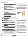
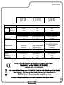
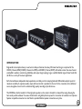
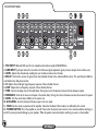
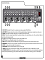
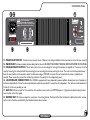
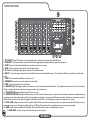
CD100
CD200
CD300
WARNING: When using electrical products, basic cautions should always be followed, including the following:
1. Read these instructions.
2. Keep these instructions safe.
3. Heed all warnings.
4. Follow all instructions.
5. Do not use this apparatus near water.
6. Clean only with a dry cloth.
7. Do not block any of the ventilation openings. Install in accordance with manufacturer’s instructions.
8. Do not install near any heat sources such as radiators, heat registers, stoves or other apparatus (including amplifiers) that produce heat.
9. An apparatus with Class I construction shall be connected to a mains socket outlet with a protective connection. Do not defeat the safety purpose of the
polarized or grounding-type plug. A polarized plug has two blades with one wider than the other. A grounding type plug has two blades and a third grounding
prong. The wide blade or third prong is provided for your safety. If the provided plug does not fit into your outlet, consult an electrician for replacement of the
obsolete outlet.
10. Protect the power cord from being walked on or pinched, particularly at plugs, convenience receptacles, and the point they exit from the apparatus.
11. Only use attachments/accessories provided by the manufacturer.
12. Use only with a cart, stand, tripod, bracket, or table specified by the manufacturer, or sold with the apparatus. When a cart is used, use caution when
moving the cart/apparatus combination to avoid injury from tip-over.
13. The mains plug or appliance coupler is used as the disconnect device and shall remain readily operable. The user should allow easy access to any mains
plug, mains coupler and mains switch used in conjunction with this unit thus making it readily operable. Unplug this apparatus during lightning storms or when
unused for long periods of time.
14. Refer all servicing to qualified service personnel. Servicing is required when the apparatus has been damaged in any way, such as when power-supply
cord or plug is damaged, liquid has been spilled or objects have fallen into the apparatus, the apparatus has been exposed to rain or moisture, does not
operate normally, or has been dropped.
15. Never break off the ground pin. Connect only to a power supply of the type marked on the unit adjacent to the power supply cord.
16. If this product is to be mounted in an equipment rack, rear support should be provided.
17. Note for UK only: If the colours of the wires in the mains lead of this unit do not correspond with the terminals in your plug‚ proceed as follows:
a) The wire that is coloured green and yellow must be connected to the terminal that is marked by the letter E‚ the earth symbol‚ coloured green or
coloured green and yellow.
b) The wire that is coloured blue must be connected to the terminal that is marked with the letter N or the colour black.
c) The wire that is coloured brown must be connected to the terminal that is marked with the letter L or the colour red.
18.This electrical apparatus should not be exposed to dripping or splashing and care should be taken not to place
objects containing liquids, such as vases, upon the apparatus.
19. Exposure to extremely high noise levels may cause a permanent hearing loss. Individuals vary considerably in
susceptibility to noise-induced hearing loss, but nearly everyone will lose some hearing if exposed to sufficiently
intense noise for a sufficient time.
The U.S. Government’s Occupational Safety and Health Administration (OSHA) has specified the following
permissible noise level exposures: According to OSHA, any exposure in excess of the above permissible limits could
result in some hearing loss. Earplugs or protectors to the ear canals or over the ears must be worn when operating this
amplification system in order to prevent a permanent hearing loss, if exposure is in excess of the limits as set forth
above. To ensure against potentially dangerous exposure to high sound pressure levels, it is recommended that all
persons exposed to equipment capable of producing high sound pressure levels such as this amplification system be
protected by hearing protectors while this unit is in operation.
ATTENTION: L’utilisation de tout appareil électrique doit être soumise aux precautions d’usage incluant:
1. Lire ces instructions
2. Gardez ce manuel pour de futures références.
3. Prétez attention aux messages de précautions de ce manuel.
4. Suivez ces instructions.
5. N’utilisez pas cette unité proche de plans d’eau.
6. N’utilisez qu’un tissu sec pour le nettoyage de votre unité.
7. N’obstruez pas les systèmes de refroidissement de votre unité et installez votre unité en fonction des instructions de ce manuel.
8. Ne positionnez pas votre unité à proximité d’une source de chaleur.
9. Un appareil avec la construction de la classe I sera relié à une sortie de douille de forces à un raccordement protecteur. Connectez toujours votre unité
sur une alimentation munie de prise de terre utilisant le cordon d’alimentation fourni.
10. Protégez les connecteurs de votre unité et positionnez les cablages pour éviter toutes déconnexions accidentelles.
11. N’utilisez que des fixations approuvées par le fabriquant.
12. Lors de l’utilsation sur pied ou pole de support, assurez dans le cas de déplacement de l’ensemble enceinte/support de prévenir tout basculement
intempestif de celui-ci.
13. La fiche d’alimentation sert au debranchement de l’apareil et doit rester aisement accessible. L’utilisateur doit laisser l’accès libre à tout cables, prises ou
interupteur connectés à cette appareil. En cas d’orage ou de longue période de non-utilisation débrancher cet apareil.
14. Seul un technicien agréé par le fabriquant est à même de réparer/contrôler votre unité. Celle-ci doit être contrôlée si elle a subit des dommages de
manipulation, d’utilisation ou de stockage (humidité,…).
15. Ne déconnectez jamais la prise de terre de votre unité.
16. Si votre unité est destinée a etre montée en rack, des supports arriere doivent etre utilisés.
17. Note pour les Royaumes-Unis: Si les couleurs de connecteurs du cable d’alimentation ne correspond pas au guide de la prise secteur, procédez comme
suit:
a) Le connecteur vert et jaune doit être connectrer au terminal noté E, indiquant la prise de terre ou correspondantaux couleurs verte ou verte et
jaune du guide.
b) Le connecteur bleu doit être connecter au terminal noté N, correspondant à la couleur noire du guide.
c) Le connecteur marron doit être connecter au terminal noté L, correspondant à la couleur rouge du guide.
18. Cet équipement électrique ne doit en aucun cas être en contact avec un quelconque liquide et aucun objet contenant un liquide, vase ou autre ne
devrait être posé sur celui-ci.
19. Une exposition à de hauts niveaux sonores peut conduire à des dommages de l’écoute irréversibles. La
susceptibilité au bruit varie considérablement d’un individu à l’autre, mais une large majorité de la population
expérimentera une perte de l’écoute après une exposition à une forte puissance sonore pour une durée prolongée.
L’organisme de la santé américaine (OSHA) a produit le guide ci-dessous en rapport à la perte occasionnée:
D’après les études menées par le OSHA, toute exposition au delà des limites décrites ci-dessus entrainera des
pertes de l’écoute chez la plupart des sujets. Le port de système de protection (casque, oreilette de filtrage,…) doit
être observé lors de l’opération cette unité ou des dommages irréversibles peuvent être occasionnés. Le port de ces
systèmes doit être observé par toutes personnes susceptibles d’être exposées à des conditions au delà des limites
décrites ci-dessus.
ACHTUNG: Beim Einsatz von Elektrogeräten müssen u.a. grundlegende Vorsichtsmaßnahmen befolgt werden:
1. Lesen Sie sich diese Anweisungen durch.
2. Bewahren Sie diese Anweisungen auf.
3. Beachten Sie alle Warnungen.
4. Befolgen Sie alle Anweisungen.
5. Setzen Sie dieses Gerät nicht in der Nähe von Wasser ein.
6. Reinigen Sie es nur mit einem trockenen Tuch.
7. Blockieren Sie keine der Lüftungsöffnungen. Führen Sie die Installation gemäß den Anweisungen des Herstellers durch.
8. Installieren Sie das Gerät nicht neben Wärmequellen wie Heizungen, Heizgeräten, Öfen oder anderen Geräten (auch Verstärkern), die Wärme erzeugen.
9. Ein Apparat mit Aufbau der Kategorie I wird an einen Hauptleitungseinfaßungsanschluß mit einem schützenden Anschluss angeschlossen.
Beeinträchtigen Sie nicht die Sicherheitswirkung des gepolten Steckers bzw. des Erdungssteckers. Ein gepolter Stecker weistzwei Stifte auf, von denen einer breiter
ist als der andere. Ein Erdungsstecker weist zwei Stifte und einen dritten Erdungsstift auf.Der breite Stift bzw. der dritte Stift dient Ihrer Sicherheit. Sollte der
beiliegende Stecker nicht in Ihre Steckdose passen, wenden Sie sich bitte an einen Elektriker, um die ungeeignete Steckdose austauschen zu lassen.
10. Schützen Sie das Netzkabel, sodass niemand darauf tritt oder es geknickt wird, insbesondere an Steckern oder Buchsen und ihren Austrittsstellen aus dem Gerät.
11. Verwenden Sie nur die vom Hersteller erhältlichen Zubehörgeräte oder Zubehörteile.
12. Verwenden Sie nur einen Wagen, Stativ, Dreifuß, Träger oder Tisch, der den Angaben des Herstellers entspricht oder zusammen mit dem Gerät verkauft wurde.
Wird ein Wagen verwendet, bewegen Sie den Wagen mit dem darauf befindlichen Gerät besonders vorsichtig, damit er nicht umkippt und möglicherweise jemand
verletzt wird.
13. Die Hauptleitungen verstopfen, oder Gerätekoppler wird während die Trennung Vorrichtung benutzt und wird bereitwillig funktionell bleiben. Der Benutzer sollte
einfachen Zugang zu allen möglichen Hauptleitungen Stecker, zu den Hauptleitungen Koppler und zum Hauptleitungen Schalter erlauben, der in Verbindung mit dieser
Maßeinheit benutzt wird, die folglich ihn bereitwillig funktionell bildet. Trennen Sie diesen Apparat während der Blitzstürme oder wenn unbenutzt, für lange
Zeitabschnitte.
14. Lassen Sie sämtliche Wartungsarbeiten von qualifizierten Kundendiensttechnikern durchführen. Eine Wartung ist erforderlich, wenn das Gerät in irgendeiner Art
beschädigt wurde, etwa wenn das Netzkabel oder der Netzstecker beschädigt wurden, Flüssigkeit oder Gegenstände in das Gerät gelangt sind, das Gerät Regen oder
Feuchtigkeit ausgesetzt wurde, nicht normal rbeitet oder heruntergefallen ist.
15.Der Erdungsstift darf nie entfernt werden. Schließen Sie nur an die Stromversorgung der Art an, die am Gerät neben dem Netzkabel angegeben ist.
16. Wenn dieses Produkt in ein Geräte-Rack eingebaut werden soll, muss eine Versorgung über die Rückseite eingerichtet werden.
17. Hinweis – Nur für Großbritannien: Sollte die Farbe der Drähte in der Netzleitung dieses Geräts nicht mit den Klemmen in Ihrem Stecker übereinstimmen, gehen Sie
folgendermaßen vor:
a) Der grün-gelbe Draht muss an die mit E (Symbol für Erde) markierte bzw. grüne oder grün-gelbe Klemme angeschlossen werden.
b) Der blaue Draht muss an die mit N markierte bzw. schwarze Klemme angeschlossen werden.
c) Der braune Draht muss an die mit L markierte bzw. rote Klemme angeschlossen werden.
18. Dieses Gerät darf nicht ungeschützt Wassertropfen und Wasserspritzern ausgesetzt werden und es muss darauf
geachtet werden, dass keine mit Flüssigkeiten gefüllte Gegenstände, wie z. B. Blumenvasen, auf dem Gerät abgestellt
werden.
19. Belastung durch extrem hohe Lärmpegel kann zu dauerhaftem Gehörverlust führen. Die Anfälligkeit für durch Lärm
bedingten Gehörverlust ist von Mensch zu Mensch verschieden, das Gehör wird jedoch bei jedem in gewissem Maße
geschädigt, der über einen bestimmten Zeitraum ausreichend starkem Lärm ausgesetzt ist. Die US-Arbeitsschutzbehörde
(Occupational and Health Administration, OSHA) hat die folgenden zulässigen Pegel für Lärmbelastung festgelegt:
Laut OSHA kann jede Belastung über den obenstehenden zulässigen Grenzwerten zu einem gewissen Gehörverlust
führen. Sollte die Belastung die obenstehenden Grenzwerte übersteigen, müssen beim Betrieb dieses
Verstärkungssystems Ohrenstopfen oder Schutzvorrichtungen im Gehörgang oder über den Ohren getragen werden, um
einen dauerhaften Gehörverlust zu verhindern. Um sich vor einer möglicherweise gefährlichen Belastung durch hohe
Schalldruckpegel zu schützen, wird allen Personen empfohlen, die mit Geräten arbeiten, die wie dieses
Verstärkungssystem hohe Schalldruckpegel erzeugen können, beim Betrieb dieses Geräts einen Gehörschutz zu tragen.
CUIDADO: Cuando use productos electrónicos, debe tomar precauciones básicas, incluyendo las siguientes:
1. Lea estas instrucciones.
2. Guarde estas instrucciones.
3. Haga caso de todos los consejos.
4. Siga todas las instrucciones.
5. No usar este aparato cerca del agua.
6. Limpiar solamente con una tela ceca.
7. No blacker ninguna de las salida de ventilación. Instalar de acuerdo a las instrucciones del fabricante.
8. No instalar cerca de ninguna Fuentes de calor come radiators, estufas, hornos u otros aparatos (incluyendo amplificadores) que produzcan calor.
9. Un aparato con la construcción de la clase I será conectado con un enchufe de zócalo de las cañerías con una conexión protectora. No retire la patilla
protectora del enchufe polarizado o de tipo “a Tierra”. Un enchufe polarizado tiene dos puntas, una de ellas más ancha que la otra. Un enchufe de tipo “a Tierra” tiene dos
puntas y una tercera “a Tierra”. La punta ancha (la tercera ) se proporciona para su seguridad. Si el enchufe proporcionado no encaja en su enchufe de red, consulte a un
electricista para que reemplaze su enchufe obsoleto.
10. Proteja el cable de alimentación para que no sea pisado o pinchado, particularmente en los enchufes, huecos, y los puntos que salen del aparato.
11. Usar solamente añadidos/accesorios proporcionados por el fabricante.
12. Usar solamente un carro, pie, trípode, o soporte especificado por el fabricante, o vendido junto al aparato. Cuando se use un carro, tenga cuidado al mover el conjunto
carro/aparato para evitar que se dañe en un vuelco. No suspenda esta caja de ninguna manera
13. Las cañerías tapan o el acoplador de la aplicación se utiliza mientras que el dispositivo de la desconexión y seguirá siendo fácilmente operable. El usuario debe
permitir el acceso fácil a cualquier cañería enchufe, a las cañerías acoplador y al interruptor de las cañerías usado conjuntamente con esta unidad así que lo hace
fácilmente operable. Desenchufe este aparato durante tormentas del relámpago o cuando es inusitado por períodos del tiempo largos.
14. Para cualquier reparación, acuda a personal de servicio cualificado. Se requieren reparaciones cuando el aparato ha sido dañado de alguna manera, como cuando el
cable de alimentación o el enchufe se han dañado, algún líquido ha sido derramado o algún objeto ha caído dentro del aparato, el aparato ha sido expuesto a la lluvia o la
humedad, no funciona de manera normal, o ha sufrido una caída.
15. Nunca retire la patilla de Tierra. Conecte el aparato sólo a una fuente de alimentación del tipo marcado al lado del cable de alimentación.
16. Si este producto va a ser enracado con más equipo, use algún tipo de apoyo trasero.
17. Nota para el Reino Unido solamente: Si los colores de los cables en el enchufe principal de esta unidad no corresponden con los terminales en su enchufe‚ proceda
de la siguiente manera:
a) El cable de color verde y azul debe ser conectado al terminal que está marcado con la letra E‚ el símbolo de Tierra (earth)‚ coloreado en verde o en verde y amarillo.
b) El cable coloreado en azul debe ser conectado al terminal que está marcado con la letra N o el color negro.
c) El cable coloreado en marrón debe ser conectado al terminal que está marcado con la letra L o el color rojo.
18. Este aparato eléctrico no debe ser sometido a ningún tipo de goteo o salpicadura y se debe tener cuidado para no poner
objetos que contengan líquidos, como vasos, sobre el aparato.
19. La exposición a altos niveles de ruido puede causar una pérdida permanente en la audición. La susceptibilidad a la
pérdida de audición provocada por el ruido varía segúnla persona, pero casi todo el mundo perderá algo de audición si se
expone a un nivel de ruido suficientemante intenso durante un tiempo determinado. El Departamento para la Salud y para la
Seguridad del Gobierno de los Estados Unidos (OSHA) ha especificado las siguientes exposiciones al ruido permisibles:
De acuerdo al OSHA, cualquier exposición que exceda los límites arriba indicados puede producir algún tipo de pérdida
en la audición. Protectores para los canales auditivos o tapones para los oídos deben ser usados cuando se opere con este
sistema de sonido para prevenir una pérdida permanente en la audición, si la exposición excede los límites indicados más
arriba. Para protegerse de una exposición a altos niveles de sonido potencialmente peligrosa, se recomienda que todas las
personas expuestas a equipamiento capaz de producir altos niveles de presión sonora, tales como este sistema de
amplificación, se encuentren protegidas por protectores auditivos mientras esta unidad esté operando.
After unpacking your amplifier check that it is factory fitted with a
three pin ‘grounded’ (or earthed) plug. Before plugging into the
power supply ensure you are connecting to a grounded earth outlet.
If you should wish to change the factory fitted plug yourself, ensure
that the wiring convention applicable to the country where the
amplifier is to be used is strictly conformed to. As an example in
the United Kingdom the cable colour code for connections are as
follows.
NOTE
This manual has been written for easy access of information. The
front and rear panels are graphically illustrated, with each control
and feature numbered. For a description of the function of each
control feature, simply check the number with the explanations
adjacent to each panel.
Your Laney amplifier has undergone a thorough two stage, predelivery inspection, involving actual play testing.
When you first receive your Laney amplifier, follow these simple
procedures:
(i) Ensure that the amplifier is the correct voltage for the
country it is to be used in.
(ii) Connect your equipment with a high quality shielded cable.
You have probably spent considerable money on your amplifier
and equipment - don’t use poor quality cable, it won’t do your
gear justice.
Please retain your original carton and packaging so in the unlikely
event that some time in the future your amplifier should require
servicing you will be able to return it to your dealer securely
packed.
Care of your Laney amplifier will prolong it’s life.....and yours!
SPECIFICATIONS
CD100
~115V
~220V/~230V
Output Power Rating
Inputs
Phantom Power
EQ
Loudspeaker Outputs
Record Out
DSP
Size (mm)
Net Weight (kg)
Gross Weight (kg)
CD300
~115V, ~220V/~230V 50/60Hz
Supply Voltage on all models:
Mains Fuse:
CD200
T3.15A L
T1.6A L
80W RMS
4 x Balanced Mic(XLR)/Line(Jack)
Aux In (RCA) w/Level control
No
Hi & Low controls per channel
T4A L
T2A L
2 x 80W RMS
5 x Balanced Mic(XLR)/Line(Jack)
Aux In (RCA) w/Level control
No
Hi & Low controls per channel
T5A L
T2.5A L
300W RMS
7 x Balanced Mic(XLR)/Line(Jack)
Aux In (RCA) w/Level control
+15V Global
Hi & Low controls per channel
7 Band Graphic (±12dB at 50,
–
–
100,400,1k,2k5,6k3,16k Peaking)
2 x Parallel Jack
4 x Jack (2 x parallel per side)
2 x Parallel Speakon
(4 ohms min.)
(4 ohms min. per side)
(4 ohms min.)
Yes (RCA)
Yes (RCA)
Yes (RCA)
Delay with time and feedback controls, Master level, and Level per channel
160*415*275 (H*W*D)
160*500*280 (H*W*D)
235*475*300 (H*W*D)
6kg
7.5kg
10.5kg
7.5kg
9kg
12.5kg
INTRODUCTION
Engineered to be simple and easy to use but not skimp on features, the Laney CD mixer head range is comprised of the
CD100 (4 channel, 80W), CD200 (5 channel, 2 x 80W) and CD300 (7 channel, 300W). All models contain the same channel
preamplifiers, auxiliary connections, global delay, and output stage topology to give a unified, flexible range of mixer heads that
will fit into a variety of live music applications.
Each channel features independent level, equalisation, and delay controls accepting balanced XLR/unbalanced jack inputs for
maximum versatility. A separate auxiliary input with level control is provided on the rear for the connection of an additional
source, alongside a record out for uncluttered high quality recordings of performances.
The CD300 also has the benefit of a 7-band graphic equaliser on the master channel for increased fine tuning, allowing the
best sound possible whatever the venue characteristics, and global phantom power for connection of condenser microphones.
Speakon compatible connectors are also fitted to provided faultless speaker connection every time.
CD100 FRONT PANEL
TIME
DELAY
DELAY
DELAY
FEEDBACK
DELAY
DELAY
1. MIC INPUT Balanced XLR input for low impedance microphone signals (200-600 Ohms).
2. LINE INPUT Jack input socket for connection of all line level signals (keyboard, signal processor, sample, drum machine, etc.).
3. LEVEL Adjusts the channel level, enabling the user to balance levels across channels.
4. DELAY Controls the amount of signal sent by the individual channel to the onboard effects section. The overall level of effects is
controlled via the delay Level control.
5. HI Adjusts the mid & high range frequency response of the individual channel.
6. LOW Adjusts the low frequency response of the individual channel.
7. TIME Controls the delay time of the inbuilt delay. Turning the control clockwise increases the time between repeats.
8. FEEDBACK Controls the amount of repeats in the inbuilt delay. Turning the control clockwise increases the amount of repeats.
9. LEVEL Sets the overall level of effects in the master mix.
10. AUX LEVEL Controls the level of the Aux input on the rear panel.
11. MAIN Sets the master output level of the amplifier. Note that the Record Out socket is not affected by this control.
12. POWER SWITCH Turns the amplifier on and off. Ensure that the master level control is set to minimum before switching on
and off to prevent potential damage to your speakers. Make all speaker connections before switching on power to the amplifier.
CD100 REAR PANEL
13. MAINS INLET SOCKET Connect to your power source. Make sure the voltage indicated on the rear panel is correct for your country!
14. MAINS FUSE This drawer contains the main safety fuse for the unit. USE ONLY THE CORRECT SIZE AND RATING SPECIFIED ON THE PANEL.
15. VOLTAGE SELECT SWITCH This is factory set to the correct voltage for the region the product is supplied to. If necessary it can be
reset by removing the mains lead and then loosening (but not removing) the screws securing the cover. The cover can then be pivoted away
from the switch which can be moved to select the alternate voltage. DO NOT reconnect the mains lead until the cover is replaced and
secured. Please ensure the correct fuse is fitted (as printed on the panel) for the voltage being used.
16. LOUDSPEAKER CONNECTIONS Two parallel jack sockets are provided for connection of loudspeakers. The minimum total
impedance is 4 ohms (2 x 8 ohm in parallel).
17. AUX IN RCA stereo input for the connection of an auxiliary source such as a CD/MP3 player etc. Signal level is adjusted using the Aux
Level control on the front panel.
18. RECORD OUT RCA stereo output for connection of recording devices. The Record Out feed is taken from before the master volume
control, and is therefore controlled by the individual channel level controls.
CD200 FRONT PANEL
TIME
DELAY
DELAY
DELAY
DELAY
FEEDBACK
DELAY
DELAY
1. MIC INPUT Balanced XLR input for low impedance microphone signals (200-600 Ohms).
2. LINE INPUT Jack input socket for connection of all line level signals (keyboard, signal processor, sample, drum machine, etc.).
3. LEVEL Adjusts the channel level, enabling the user to balance levels across channels.
4. DELAY Controls the amount of signal sent by the individual channel to the onboard effects section. The overall level of effects is
controlled via the delay Level control.
5. HI Adjusts the mid & high range frequency response of the individual channel.
6. LOW Adjusts the low frequency response of the individual channel.
7. TIME Controls the delay time of the inbuilt delay. Turning the control clockwise increases the time between repeats.
8. FEEDBACK Controls the amount of repeats in the inbuilt delay. Turning the control clockwise increases the amount of repeats.
9. LEVEL Sets the overall level of effects in the master mix.
10. AUX LEVEL Controls the level of the Aux input on the rear panel.
11. MAIN Sets the master output level of the amplifier. Note that the Record Out socket is not affected by this control.
12. POWER SWITCH Turns the amplifier on and off. Ensure that the master level control is set to minimum before switching on
and off to prevent potential damage to your speakers. Make all speaker connections before switching on power to the amplifier.
CD200 REAR PANEL
MAXIMUM POWER CONSUMPTION
240 WATTS 50/60Hz
CAUTION: TO REDUCE THE RISK OF FIRE REPLACE
FUSE WITH SAME TYPE AND RATING.
ATTENTION: POUR RÉDUIRE LE RISQUE DU FEU
REMPLACEZ AVEC LE MÊMES TYPE ET ESTIMATION.
WARNING: THIS APPARATUS MUST BE EARTHED.
www.laney.co.uk
N15039
SUPPLY VOLTAGE & FUSE RATING:
120 V
MODEL
VOLTAGE SELECT
SPEAKER OUTPUT A
(MINIMUM 4 OHM)
SERIAL NUMBER
SPEAKER OUTPUT B
(MINIMUM 4 OHM)
CAUTION - RISK OF ELECTRIC SHOCK DO NOT OPEN
ATTENTION - RISQUE DE DÉCHARGE ÉLECTRIQUE, NE S'OUVRE PAS
CAUTION - HOT SURFACE!
DESIGNED IN THE UK BY LANEY
13. MAINS INLET SOCKET Connect to your power source. Make sure the voltage indicated on the rear panel is correct for your country!
14. MAINS FUSE This drawer contains the main safety fuse for the unit. USE ONLY THE CORRECT SIZE AND RATING SPECIFIED ON THE PANEL.
15. VOLTAGE SELECT SWITCH This is factory set to the correct voltage for the region the product is supplied to. If necessary it can be
reset by removing the mains lead and then loosening (but not removing) the screws securing the cover. The cover can then be pivoted away
from the switch which can be moved to select the alternate voltage. DO NOT reconnect the mains lead until the cover is replaced and
secured. Please ensure the correct fuse is fitted (as printed on the panel) for the voltage being used.
16. LOUDSPEAKER CONNECTIONS The CD200 is equipped with two independent power amplifiers, allowing two sets of speakers to
be driven independently. On each side, two parallel jack sockets are provided for connection of loudspeakers. The minimum total impedance is
4 ohms (2 x 8 ohm in parallel) per side.
17. AUX IN RCA stereo input for the connection of an auxiliary source such as a CD/MP3 player etc. Signal level is adjusted using the Aux
Level control on the front panel.
18. RECORD OUT RCA stereo output for connection of recording devices. The Record Out feed is taken from before the master volume
control, and is therefore controlled by the individual channel level controls.
CD300 FRONT PANEL
DELAY
DELAY
DELAY
DELAY
DELAY
DELAY
DELAY
FEEDBACK
TIME
DELAY
1. MIC INPUT Balanced XLR input for low impedance dynamic or condenser microphone signals (200-600 Ohms).
2. LINE INPUT Jack input socket for connection of all line level signals (keyboard, signal processor, sample, drum machine, etc.).
3. LEVEL Adjusts the channel level, enabling the user to balance levels across channels.
4. LOW Adjusts the low frequency response of the individual channel.
5. HI Adjusts the mid & high range frequency response of the individual channel.
6. DELAY Controls the amount of signal sent by the individual channel to the onboard effects section. The overall level of effects is controlled via the delay Level
control.
7. LEVEL Sets the overall level of effects in the master mix.
8. FEEDBACK Controls the amount of repeats in the inbuilt delay.
9. TIME Controls the delay time of the inbuilt delay.
10. GRAPHIC EQ A 7-Band graphic equaliser to fine tune your sound and help eliminate feedback issues. This is applied to the master mix. EQ is best used subtly.
Cutting or boosting all bands, or using extreme settings can reduce clarity and dynamics.
11. PHANTOM LED Indicates whether Phantom Power is on or off.
12. PHANTOM SWITCH Enables global Phantom power on the XLR sockets. Phantom power is required for most condenser microphones. Unpowered dynamic
microphones can be used simultaneously, and will not be damaged by connecting them to an input when Phantom is activated. However, use caution when connecting
sensitive ribbon mics, as these may easily be damaged if connected to Phantom Power. If in doubt, please consult your microphone’s user manual.
13. LEVEL LEDS Displays the master level of the amplifier. Adjust the Main control so that the volume peaks in your signal cause the yellow LED to light, only very
occasionally moving into red. Running the amplifier with the red LEDs lit all the time will result in output distortion and compromise signal quality.
14. MAIN Sets the master output level of the amplifier. Note that the Record Out socket is not affected by this control.
15. AUX LEVEL Controls the input level of the Aux input on the rear panel.
CD300 REAR PANEL
MAXIMUM POWER CONSUMPTION
450 WATTS 50/60Hz
VOLTAGE SELECT
N15039
SUPPLY VOLTAGE & FUSE RATING:
16. MAINS INLET SOCKET Connect to your power source. Make sure the voltage indicated on the rear panel is correct for your country!
17. MAINS FUSE This drawer contains the main safety fuse for the unit. USE ONLY THE CORRECT SIZE AND RATING SPECIFIED ON THE PANEL.
18. VOLTAGE SELECT SWITCH This is factory set to the correct voltage for the region the product is supplied to. If necessary it can be
reset by removing the mains lead and then loosening (but not removing) the screws securing the cover. The cover can then be pivoted away
from the switch which can be moved to select the alternate voltage. DO NOT reconnect the mains lead until the cover is replaced and
secured. Please ensure the correct fuse is fitted (as printed on the panel) for the voltage being used.
19. POWER SWITCH Turns the amplifier on and off. Ensure that the master level control is set to minimum before switching on and
off to prevent potential damage to your speakers. Make all speaker connections before switching on power to the amplifier.
20. AUX IN RCA stereo input for the connection of an auxiliary source such as a CD/MP3 player etc. Signal level is adjusted using Aux Level
on the front panel.
21. RECORD OUT RCA stereo output for connection of recording devices. The Record Out feed is taken from before the master volume
control, and is therefore controlled by the individual channel level controls.
22. LOUDSPEAKER CONNECTIONS Two parallel speakon compatible connectors are provided for the connection of loudspeakers.
For both sockets, signal is present between pins +1 and -1. The minimum total impedance is 4 ohms (2 x 8 ohm in parallel).
23. FAN OUTLET The CD300 is fan cooled. Do not obstruct the vents, and ensure adequate ventilation.
BLOCK DIAGRAM
Aux In
Channel 1 only shown
Mic
Inputs 2, 3, etc.
LOW
Rec Out
HI
Aux Level
Level
Line
Power amp
2 Band EQ
Time (Rate)
Feedback (Repeats)
Loudspeakers
Main Level
DELAY
DELAY
Delay CH2, CH3, etc.
Level
CD100
Aux In
Channel 1 only shown
Mic
Rec Out
Power amp
Loudspeakers
Inputs 2, 3, etc.
LOW
HI
Aux Level
Level
2 Band EQ
Time (Rate)
Line
Feedback (Repeats)
DELAY
Loudspeakers
Power amp
Main Level
DELAY
Delay CH2, CH3, etc.
Level
CD200
Mic
Aux In
Channel 1 only shown
Phantom Power
Rec Out
Inputs 2, 3, etc.
+12V
LOW
HI
Aux Level
Level
1+
Time (Rate)
Line
Loudspeakers
Power amp
2 Band EQ
DELAY
1-
Main Level
7 Band EQ
1+
DELAY
22+
Feedback (Repeats)
22+
1-
Delay CH2, CH3, etc.
CD300
Level
SAMPLE SETUP
RECORD OUT
AUX IN
REC OUT
SPEAKER OUT
SPEAKER OUT
PA ENCLOSURE
8Ω
MP3
PA ENCLOSURE
8Ω
CH1
CH2
CH3
CH4
CH5
CH6
CH7
E-DRUM KIT
MIC
MIC
BASS COMBO
MIC
FX UNIT
KEYBOARD
*CD300 shown
BASS
GUITAR
NOTES
NOTES
.3