1
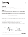
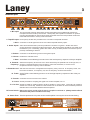
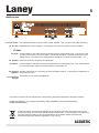
Laney
LA30C & LA65C
USER MANUAL
Laney
1
IMPORTANT SAFETY INSTRUCTIONS
WARNING: When using electric products, basic cautions should always be followed, including the following.
1.
Read all safety and operating instructions before using this product
2.
The product should be powered by a three pin `grounded (or earthed) plug connected to a power socket
with a grounded earth outlet.
3.
All safety and operating instructions should be retained for future reference
4.
Obey all cautions in the Operating instructions and on the back of the unit
5.
All operating instructions should be followed
6.
This product should not be used near water, i.e. a bathtub, sink, swimming pool, wet basement, etc.
7.
This product should be located so that its position does not interfere with its proper ventilation. It should
not be placed flat against a wall or placed in a built up enclosure that will impede the flow of cooling air.
8.
This product should not be placed near a source of heat such as stove, radiator, or another heat
producing amplifier.
9.
Connect only to a power supply of the type marker on the unit adjacent to the power supply cord.
10.
Never break off the ground pin on a power supply cord.
11.
Power supply cords should always be handled carefully. Never walk or place equipment on power supply
cords.Periodically check cords for cuts or signs of stress, especially at the plug and the point where the
chord exits the unit.
12.
The power supply cord should be unplugged when the unit is to be unused for long periods of time.
13.
If this product is to be mounted in an equipment rack, rear support should be provided.
14.
The user should allow easy access to any mains plug, mains coupler and mains switch used in
conjunction with this unit thus making it readily operable.
15.
Metal parts can be cleaned with a damp cloth. The vinyl covering used on some units can be cleaned
with a damp cloth or ammonia based household cleaner if necessary. Disconnect the unit from the power
supply before cleaning.
16.
Care should be taken so that objects do not fall and liquids are not spilled into the unit through any
ventilation holes or openings. On no account place drinks on the unit.
17.
A qualified service technician should check the unit if:
! The power cord has been damaged
! Anything has fallen or spilled into the unit
! The unit does not appear to operate correctly
! The unit has been dropped or the enclosure damaged.
18.
The user should not attempt to service the equipment. All service work is done by a qualified service
technician.
19.
Exposure to extremely high noise levels may cause a permanent hearing gloss. Individuals vary
considerably in susceptibility to noise induced hearing loss, but nearly everyone will lose some hearing if
exposed to sufficientlyintense noise for a sufficient time. The U.S. Government's Occupational Safety and
Health Administration (OSHA) has specified the following permissible noise level exposure.
Duration Per Day In Hours
Sound Level dBA, slow response
8
90
6
92
4
95
3
97
2
100
1½
102
1
105
½
110
¼ or less
115
According to OSHA, any exposure in excess of the above permissible limits could result in some hearing loss.
Ear plugs or protectors in the ear canals or over the ears must be worn when operating this amplification system
in order to prevent a permanent hearing loss if exposure exceeds the limits set forth above. To ensure against
potentially dangerous exposure to high sound pressure levels it is recommended that all persons exposed to
equipment capable of producing high sound pressure levels such as this amplification system be protected by
hearing protectors while this unit is in operation.
SAVE THESE INSTRUCTIONS
ACOUSTIC
Laney
2
INTRODUCTION
Congratulations on your decision to purchase a Laney amplifier.
Laney products are designed with ease of operation as a primary objective, however to ensure you derive the best from
your new amplifier, it is important you take time to read this user manual and to familiarise yourself with the control
functions and facilities available.
BEFORE
SWITCHING ON
After unpacking your amplifier check that it is factory fitted with a three pin 'grounded' (or earthed) plug. Before
plugging into the power supply ensure you are connecting to a grounded earth outlet.
If you should wish to change the factory fitted plug yourself, ensure that the wiring convention applicable to the
country where the amplifier is to be used is strictly conformed to. As an example in the United Kingdom the cable
colour code for connections are as follows;
EARTH OR GROUND - GREEN/YELLOW
NEUTRAL - BLUE
LIVE - BROWN
This manual has been written for easy access of information. The front and rear panels of each unit are
graphically illustrated, with each control and feature numbered. For a description of the function of each control
feature, simply check the number with the explanations adjacent to each panel.
Your Laney dedicated ACOUSTIC amplifier has undergone a thorough two stage, pre-delivery inspection, involving
actual play testing, as well as burn in.
When you first receive your Laney dedicated ACOUSTIC amplifier, follow these simple procedures:
(I) Ensure that the amplifier is set at the correct voltage for the country it is to be used in.
(ii) Connect your instrument with a high quality shielded instrument cable. Use of cheap cables will compromise
the sound of your instrument and your amplifier.
If there is a problem with your Laney amplifier
DON'T
DO
PHONE YOUR DEALER!
Care of your Laney amplifier will prolong it's life.....and yours!.
ACOUSTIC
Laney
3
LA30C front panel
1
4
5
2
Instrument
3
8
1
Gain
1
2
3
8
1
10
0
CD In
Passive
4
- 0+
Anti-Feedback
1
5
1
1K
- 0+
4
LA30C
5
5
5
1
7
8
32
4
Acoustic Amplifier
6
2 3
4
5
5
4
1
33
4
100
1
2 2
3
3
4
5
- 0+
2
2
4
10
500
1
3
9
0
Active
1
2
7
2
9
Mic
6
3
7
2
5
4
6
1
9
0
0
10
Paramid
Volume Chorus Bass
Freq
Level
Treble
Reverb
Insert
Line Out
Power
6
8
9
10
11
12
13
14
5
7
1. Mic Input: The input socket has been designed to accept both balanced and unbalanced signals from
microphones with an XLR input connector. Good quality low impedance condensor or dynamic
mics should preferably be used for best results, these will ensure the best possible results from
hand-held instruments or closely mic'd instruments.
2. Tape/CD input: Phono (RCA) sockets are provided for the connection of tape/CD machines.
3. Gain: Controls the overall signal level of the mic and the tape/CD auxiliary inputs.
4. Guitar Inputs: Active and Passive/Active inputs are provided for connection of guitars. Guitars with active
circuitry should be connected via the Active socket. Non-active guitars should be connected using
the Passive input. Incidentally, guitars with active circuitry could be placed in the Passive input if
pre-amp overloading is desired.
5. Volume: Controls the overall listening volume of the guitar inputs.
6. Chorus: Enables the onboard chorus.
7. Bass: Active Bass control allowing boost and cut of the low-frequency response of the pre-amplifier.
8. Paramid- Selects the frequency at which the cut or boost selected by the paramid level control (9) acts; to
Frequency: access LO mid frequencies turn the frequency control anti-clockwise, to access HI mid
frequencies turn the frequency control clockwise.
9. Paramid-Level: Sets the level of boost or cut applied to the frequency set by control 8: for frequency boost, turn
the control clockwise; for frequency cut, turn the frequency control anti-clockwise.
10. Treble: Active Treble control allowing boost or cut of the high frequency response of the of the preamplifier.
11. Reverb: Controls the level of reverb on the channel.
12. Insert: Socket provided for accepting the signal from another amplifier, see 13
13. Line Out: Socket provided for sending signal to another amplifier or mixing desk. Connecting an LA30C to
another non chorus amp, such as an LA30 via the Line out socket to an insert socket will produce a
dramatic stereo chorus effect between the two amplifiers.
14. Power Switch: Main power switch, the led will be lit when the amplifier is switched on. (Always switch off and
disconnect the power cord when not in use).
15. Power Fuse: This fuse protects the AC power of the overall amplifier. Use only the correct size and rating.
LA30C
MODEL
POWER SOURCE
~100VAC 50/60HZ
~120VAC 50/60HZ
T500MA L / 125V
POWER CONSUMPTION
50 WATTS ~50/60HZ
SERIAL
NUMBER
~230V AC 50/60HZ
~240V AC 50/60HZ
T250MA L / 250V
ABC- 1 2 3 4 5 4 6 7 8 9 0 - 1 2 3 4 5 6 7 8 9
DESIGNED IN THE UK BY LANEY
15
LA30C rear panel
N15039
CAUTION
RISK OF ELECTRIC SHOCK DO NOT OPEN
!
Laney
P O W E R TO T H E M U S I C
www.laney.co.uk
MADE IN CHINA FABRIQUE EN CHINE
WARNING - TO REDUCE THE RISK OF FIRE OR ELECTRIC SHOCK
DO NOT EXPOSE THIS APPLIANCE TO RAIN OR MOISTURE.
CAUTION - FOR CONTINUED PROTECTION AGAINST RISK OF
FIRE REPLACE ONLY WITH SAME TYPE AND RATED FUSE.
CAUTION - TO REDUCE THE RISK OF ELECTRIC SHOCK DO NOT
REMOVE COVERS.NO USER SERVICEABLE PARTS INSIDE. REFER
SERVICING TO QUALIFIED PERSONNEL ONLY.
WARNING - THIS EQUIPMENT MUST BE EARTHED.
ATTENTION - REMPLACER LE FUSIBLE SEULEMENT PAR LE
MEME TYPE ET LE MEME CALIBRE.
AVIS - RISQUE DE CHOC ELECTRIQUE - NE PAS OUVRIR.
ATTENTION - DEBRANCHER LE CORDON D’ALIMENTATION
AVANT TOUTE INTERVENTION.
ACOUSTIC
Laney
4
LA65C front panel
Instrument Channel 1
Auxillary Channel 2
4
5
6
3
1
7
8
2
1
9
10
0
- 0+
1
2
1
2
- 0+
4
4
5
5
3
4
6
8
1
5
1
7
2
4
5
5
3
2
3 3
3
4
1
2
9
10
0
- 0+
Anti-Feedback
1
2
1
2
- 0+
4
4
5
5
1
3
4
3
Aux
Input
Gain
Bass
Treble
Input
Gain
Bass
5
1K
100
1
2
3
4
5
6
7
8
Treble Phase
4
5
9
10
Level
11
12
6
1
13
4
7
5
9
0
10
Reverb
2 4 5
6
3
8
1
0
10
Depth
14
15
16
7
9
0
CD In
17 18
1
8
1
10
Level
6
2
9
0
5
3
8
1
1
4
7
2
9
Rate
LA65C Acoustic Amplifier
6
3
7
8 2
1
5
Freq
5
2
Paramid
Mic
4
3
2
4
Chorus
2
1
3
4
5
- 0+
2
2
3 3
3
500
1
2
10
0
Volume
Power
19
20
Auxillary Channel 2:
1. Mic Input: The input socket has been designed to accept both balanced and unbalanced signals from
microphones with an XLR input connector. Good quality low impedance condensor or dynamic
mics should preferably be used for best results, these will ensure the best possible results from
hand-held instruments or closely mic'd instruments.
2. Aux Input: Auxilluary jack input for jack equipped mics and sound sources such as keyboards drum
machines etc.
3. Gain: Controls the signal level for instruments connected to Auxilluary Channel 2.
4. Bass: Active Bass control allowing boost and cut of the low-frequency response of the instruments
connected to Auxilluary Channel 2.
5. Treble: Active Treble control allowing boost or cut of the high frequency response of the instruments
connected to Auxilluary Channel 2.
Instrument Channel 1:
6. Input: Jack input for Instrument Channel, connect guitars and other musical instruments via this
7. Gain: socket.
8. Bass: Controls the signal level for instruments connected to Instrument Channel 1.
Active Bass control allowing boost and cut of the low-frequency response of the instruments
9. Treble: connected to Instrument Channel 1.
Active Treble control allowing boost or cut of the high frequency response of the instruments
Anti-Feedback:
10. Phase Switch: Phase switch assists in the cancellation of low frequency oscillations which are associated with
acoustic guitar feedback.
11/12. Paramid- Paramid controls: Used in conjunction with each other to to eliminate feedback, by determining
Freq/Level: the boosted or cut frequency and the boosted or cut level of frequency.
Chorus:
13. Chorus Assign: Assigns Chorus to either channel 1, channel 2 or both.
14/15. Chorus- Chorus controls: Used in conjunction with each other to determine the rate and depth of the
Rate/Depth: selected chorus sweep.
Reverb:
16. Reverb Assign: Assigns reverb to either channel 1, channel 2 or both.
17. Reverb Level: Controls the level of reverb on the channel.
18. Tape/CD input: Phono (RCA) sockets are provided for the connection of tape/CD machines.
19. Volume: Controls the overall listening level of the amplifier.
20. Power Switch: Main power switch, the led will be lit when the amplifier is switched on. (Always switch off and
disconnect the power cord when not in use).
ACOUSTIC
Laney
5
LA65C rear panel
22 23
21
24
25
26 27
21. Fuse Holder: This fuse protects the AC power of the overall amplifier. Use only the correct size and rating.
22. D.I. Out: Balanced Direct Inject output for connecting to external mixing desk or power amplifier.
FX Loop:
23. Send: Jack provided for use with external processing devices such as delays etc. Can also be used
as a line out providing a line level signal. This socket should be connected to the input of the
effects device. The output of the effects device should be connected to the FX return - 25.
24. Disable: Removes the effects loop from the signal path.
25. Return: Jack provided for use with external processing devices such as delays etc. This socket should
be connected to the output of the effects device connected to 23.
26. External Speaker connection for connecting an external speaker cabinet - total minimum impedance of
Speaker: no less than 8 ohms.
27. Headphone Jack socket for connecting headphones.
Socket:
This product conforms to the requirements of the following European Regulations, Directives & Rules:CE Mark (93/68/EEC), Low Voltage (72/23/EEC), EMC (93/68/EEC), RoHS (EU2002/95/EC),
WEEE (EU2002/96/EC)
In order to reduce environmental damage, at the end of its useful life, this product must not be
disposed of along with normal household waste to landfill sites. It must be taken to an approved
recycling centre according to the recommendations of the WEEE (Waste Electrical and
Electronic Equipment) directive applicable in your country.
ACOUSTIC
1.
Laney
POWER TO THE MUSIC
LANEY AMPLIFICATION
w w w. l a n e y. c o . u k
In the interest of continued product development, Laney reserves the right to amend product specification without prior notification.