1
Precision Cooling
For Business-Critical Continuity™
Liebert® DM Chilled Water Series
User Manual
LIEBERT_DM Chilled Water Series Cooling Unit
User Manual
Version: V1.0
Revision date: Nov. 03, 2012
ROM: 31012828
Emerson Network Power provides customers with technical support. Users may contact the nearest
Emerson local sales office or service center.
Copyright © 2010 by Emerson Network Power Co., Ltd.
All rights reserved. The contents in this document are subject to change without notice.
Emerson Network Power Co., Ltd.
Address: No.1 Kefa Rd., Science & Industry Park, Nanshan District 518057, Shenzhen China
Homepage: www.emersonnetworkpower.com.cn
E-mail: [email protected]
Contents
Chapter 1 Overview ............................................................................................................................................................ 1
1.1 Model description .....................................................................................................................................................................1
1.2 Product introduction .................................................................................................................................................................1
1.3 Key parts ..................................................................................................................................................................................1
1.4 Options .....................................................................................................................................................................................2
1.4.1 Remote monitor............................................................................................................................................................2
1.4.2 Energy-saving card .......................................................................................................................................................2
1.5 Environmental requirement ......................................................................................................................................................2
1.5.1 Operating environment .................................................................................................................................................2
1.5.2 Storage environment ....................................................................................................................................................2
Chapter 2 Mechanical Installation ....................................................................................................................................... 3
2.1 Unpacking inspection ...............................................................................................................................................................3
2.2 Installation precaution ..............................................................................................................................................................3
2.3 System installation layout.........................................................................................................................................................3
2.3.1 General layout ..............................................................................................................................................................3
2.3.2 Mechanical parameters .................................................................................................................................................4
2.4 Unit installation ........................................................................................................................................................................7
2.4.1 Equipment room requirement .......................................................................................................................................7
2.4.2 Installation space requirement ......................................................................................................................................8
2.4.3 Installation steps ...........................................................................................................................................................8
2.5 Installation of unit pipes .........................................................................................................................................................11
2.6 Items for inspection ................................................................................................................................................................12
Chapter 3 Electric Installation............................................................................................................................................ 13
3.1 Task description .....................................................................................................................................................................13
3.2 Precautions .............................................................................................................................................................................13
3.3 Connection of unit power cable ..............................................................................................................................................13
3.4 Connection of control cable....................................................................................................................................................14
3.4.1 Connection of control terminal ...................................................................................................................................14
3.4.2 Connection of monitoring cable .................................................................................................................................15
3.5 Connection of energy-saving card ..........................................................................................................................................16
3.6 Items for inspection ................................................................................................................................................................18
Chapter 4 System Test...................................................................................................................................................... 19
4.1 Startup inspection ...................................................................................................................................................................19
4.2 Function test ...........................................................................................................................................................................19
Chapter 5 Microprocessor ................................................................................................................................................. 20
5.1 Features ..................................................................................................................................................................................20
5.2 Appearance .............................................................................................................................................................................20
5.3 Display ...................................................................................................................................................................................21
5.4 Control key .............................................................................................................................................................................21
5.4.1 Function description ...................................................................................................................................................21
5.4.2 Operation example .....................................................................................................................................................22
5.5 Control interface .....................................................................................................................................................................22
5.5.1 Shutdown interface .....................................................................................................................................................22
5.5.2 Startup interface .........................................................................................................................................................22
5.5.3 Normal interface.........................................................................................................................................................23
5.5.4 Password interface .....................................................................................................................................................23
5.6 Menu structure........................................................................................................................................................................23
5.6.1 Main menu .................................................................................................................................................................23
5.6.2 Alarm menu................................................................................................................................................................24
5.6.3 Setting point ...............................................................................................................................................................27
5.6.4 System status ..............................................................................................................................................................27
5.6.5 System menu ..............................................................................................................................................................28
5.6.6 Help menu ..................................................................................................................................................................31
Chapter 6 System Maintenance ........................................................................................................................................ 33
6.1 Electric inspection ..................................................................................................................................................................33
6.2 Unit maintenance....................................................................................................................................................................33
6.2.1 Filter ...........................................................................................................................................................................33
6.2.2 Fan .............................................................................................................................................................................34
6.2.3 Drainage pipe .............................................................................................................................................................34
6.2.4 Water flow regulating valve .......................................................................................................................................34
6.3 Maintenance checklist ............................................................................................................................................................36
Chapter 7 Failure Diagnosis and Troubleshooting ............................................................................................................ 37
Appendix 1 Menu Structure Diagram ................................................................................................................................ 41
Appendix 2 List of Parameters .......................................................................................................................................... 42
Appendix 3 Introduction to SiteMonitor Software .............................................................................................................. 44
Appendix 4 Symbol Table for Toxic/Hazardous Substances and Elements ...................................................................... 46
Chapter 1
Overview
1
Chapter 1 Overview
This chapter mainly introduces the model description, product profile, main parts, optional parts and environment
requirement of Liebert_DM chilled water series cooling unit.
1.1 Model description
The model description of Liebert_DM chilled water series cooling unit is as shown in Fig. 1-1
DM H 09 U M H 2
Version
Cooling System . C:cooling onl y: O:with heater;
H: with heater and humid itier
Power Supply. M:3-ph/380V/50Hz
Air Discharge. U:upflow; F:downflow; D:duct
Cooling Capactity. 09:8.2kW; 12:11.6kW; 17:16.3kW; 25:23.2kW
Chilled Water.
Liebert_DM
Fig.1- 1 Model description
1.2 Product introduction
The Liebert_DM chilled water series cooling unit is a small precise environment control system. It is especially
designed for the cooling of electronic equipment and applicable to the environment control of equipment room or
computer room. It is highly reliable and able to provide a proper running environment for the precision equipment, such
as sensitive equipment, industry process equipment, communication equipment and computer.
The Liebert_DM chilled water series cooling unit is equipped with microprocessor and able to automatically switch
functions according to the setting values of the program and the indoor environment conditions.
1.3 Key parts
The unit is composed of such key parts as chilled water coil, fan, microprocessor, screen and water flow regulating
valve. For the optional parts, please refer to 1.4 Options.
Chilled water coil
Fin type heat exchanger is adopted. The chilled water coil is designed and verified for specific models to ensure the
distribution evenness of chilled water in all the loops and maximize the heat exchange efficiency.
Fan
Centrifugal fan of high efficiency and high reliability is adopted, which features large blast volume, long air supply
distance, direct drive and convenient maintenance.
Microprocessor
User interface of simple operation is provided. Multi-level password protection, auto power recovery, high/low voltage
protection and phase loss protection are provided. Expert level failure diagnosis system is configured to automatically
display the failure contents and facilitate the equipment maintenance by the service personnel.
User Manual of Liebert_DM Chilled Water Series Cooling Unit
2
Chapter 1
Overview
Water flow regulating valve
The water flow regulating valve can regulate the chilled water flow according to the cooling demand. The water flow
regulating valve adopts union swivel for the connection with the system pipes, which is convenient for the onsite
installation and maintenance.
Filter
High polymer dust absorption filtering material is adopted. It has compact structure and is easy for maintenance.
1.4 Options
1.4.1 Remote monitor
The Liebert_DM chilled water series cooling unit adopts the standard protocols of Ministry of Information Industry. For
details, please refer to Centralized Power Equipment, Air Conditioning and Environment Monitoring and Management
System for Communication Stations, Part III: Protocol for Front-end Intelligent Equipment. It realizes the
communication with the host computer through the RS485 port and is controlled by the host software. For details
about the monitoring software of Emerson, SiteMonitor, please refer to Appendix IV Introduction to SiteMonitor
Monitoring Software.
1.4.2 Energy-saving card
The Liebert_DM chilled water series cooling unit adopts external energy-saving card to monitor the maximum
temperature in the room. The energy-saving card is deployed in the place with large thermal load and high
temperature. This cooling unit can be equipped with up to 4 energy-saving cards. When the temperature values
measured by all the energy-saving cards are lower than the setting value of “sleep temperature”, and only the internal
fan needs to run, if “sleep mode” is set as “enabled”, the cooling unit will shut down the internal fan and enter the sleep
mode, so as to realize energy efficiency.
1.5 Environmental requirement
1.5.1 Operating environment
The operating environment shall meet the standards of GB4798.3-90. For details, please refer to Table 1-1.
Table 1-1 Requirement of operating environment
Item
Requirement
Vertical installation, with the installation base ≥150mm
Indoor temperature: 4ºC~40ºC
Chilled water inlet temperature: 5ºC~12ºC
Installation
Ambient temperature
altitude
<1000m, derated when it is more than 1000m
Operating voltage range
3N~380V (-15%~+20%) , 50Hz
1.5.2 Storage environment
The storage environment shall meet the standards of GB4798.3-1996. For details, please refer to Table 1-2.
Table 1-2 Requirement of storage environment
Item
Storage environment
Ambient humidity
Ambient temperature
Storage time
Requirement
Indoor, clean (free of dust)
5%RH~85%RH
-20ºC~+54ºC
No more than 6 months in total (transportation plus storage), performance needs to be reevaluated after
6 months
User Manual of Liebert_DM Chilled Water Series Cooling Unit
Chapter 2
Mechanical Installation
3
Chapter 2 Mechanical Installation
This chapter will describe the mechanical installation of the Liebert_DM chilled water series cooling unit in detail,
including unpacking inspection, unit installation and pipe installation.
2.1 Unpacking inspection
Move the equipment to the place closest to the final installation site before unpacking.
In case any loss or damage of any parts is discovered during inspection, the same shall be reported to the carrier
immediately. Concealed damages noted shall also be reported to the carrier and the local office of the goods supplier.
Please do not accept the damaged equipment.
2.2 Installation precaution
1. The Liebert_DM chilled water series cooling unit adopts standalone installation mode. The unit must be installed on
the ground of the equipment room or computer room.
2. Before installing the equipment, check if the installation environment meets the relevant requirements as specified in
1.5 Environmental Requirement. And check if the building needs to be reformed for the pipe laying, wiring and
ventilation pipe mounting.
3. Install the equipment strictly according to the design drawing, and reserve corresponding installation/maintenance
space. Please refer to the engineering dimensions provided by the manufacturer.
2.3 System installation layout
2.3.1
General layout
The general layout of the system is as shown in Fig.2-1.
Air discharge valve
放气阀
换热器盘管
Heat
exchanger coil
水流量调节阀
Water
flow regulating valve
Holding平衡阀或隔离阀*
valve or isolating valve *
Chilled冷冻水进口
water inlet
Water
filter *
水过滤器*
Isolating
隔离阀*
valve *
Chilled 冷冻水出口
water outlet
Chilled water
冷冻水进出
软接口*
Soft
joint * 口螺纹连接
inlet/outlet
threaded joint
排水阀*
Water discharge valve *
Fig.2-1 General layout diagram
Note
1.
: Pipeline provided by the manufacturer.
2.
: Pipeline laid onsite (by the technical staff)
3.*: These components are not provided by Emerson Network Power Co., Ltd, but they are recommended to be used
for the normal operation of the system and maintenance.
4. After finishing the installation, air discharge must be carried out before pouring water so as to ensure the heat
transfer effect of the heat exchanger.
5. In winter in the northern region, the air conditioning unit must be emptied of water to prevent frosting the heat
exchanger if it will be idle for a long time.
User Manual of Liebert_DM Chilled Water Series Cooling Unit
4
Chapter 2
Mechanical Installation
2.3.2 Mechanical parameters
Dimensions (mm)
For the mechanical parameters of the unit, please refer to Fig.2-2 and Table 2-1.
60 8
57
5
5 10
38
1740
1900
6
DMH09 unit
DMH12 unit
1202
38
5
6
DMH17 unit
1900
1740
1102
57
DMH25 unit
Fig.2-2 Outline dimensions of the units (unit: mm)
User Manual of Liebert_DM Chilled Water Series Cooling Unit
Chapter 2
Mechanical Installation
Table 2-1 Outline dimensions and weights of the units
Product model
DMH09
DMH12
DMH17
DMH25
Size (W×D×H) (mm)
510×386×1740
608×575×1900
1102×386×1740
1202×575×1900
Net Weight (kg)
≤90
≤127
≤169
≤210
Base cutting position and dimensions
The base cutting position and dimensions are as shown in Fig.2-3.
Bac k of the unit
Chilled w ater outlet
Right s ide of the unit
Lef t s ide of the unit
Chilled w ater inlet
Cablet
inlet
Condens ed w ater
drainage hole
4 ground retaining holes
Front of the unit
Base cutting position of DMH09 unit
Back of the unit
Chilled water outlet
Chilled water inlet
Right side of the unit
Left side of the unit
Condensed water
drainage hole
Cablet inlet
4 ground retaining holes
Front of the unit
Base cutting position of DMH12 unit
User Manual of Liebert_DM Chilled Water Series Cooling Unit
5
6
Chapter 2
Mechanical Installation
Bac k of the unit
Chilled w ater outlet
Lef t s ide of
the unit
Chilled w ater inlet
Right s ide
of the unit
Condens ed w ater drainage hole
Cablet inlet
4 ground retaining holes
Front of the unit
Base cutting position of DMH17 unit
Bac k of the unit
Chilled w ater outlet
Chilled w ater inlet
Lef t s ide
of the unit
Right s ide of
the unit
Cablet
Condens ed w ater drainage hole
inlet
4 ground retaining holes
Front of the unit
Base cutting position of DMH25 unit
Fig.2-3 Base cutting position and dimensions (unit: mm)
Side plate cutting position dimensions
If it is unable to lay pipes and cables from the base, side connection may be adopted. The position and size of the
knock-out holes are as shown in Fig.2-4. The inlet and outlet can be selected according to the actual situation, but any
two of the pipes, power cables and signal cables shall not enter/exit the unit through the same hole.
User Manual of Liebert_DM Chilled Water Series Cooling Unit
Chapter 2
F ro n t o f t h e u n it
Mechanical Installation
7
B a c k o f t h e u n it
C h ille d wa t e r o u t le t
C h ille d wa t e r in le t
DMH09/DMH17 side
Back of the unit
Front of the unit
Chilled water outlet
Chilled water inlet
plate
DMH09/DMH25 side plate
Fig.2-4 Side plate knock-out hole (unit: mm)
2.4 Unit installation
2.4.1 Equipment room requirement
The detailed requirements on equipment room are as follows:
1. The equipment room shall have good thermal insulation and air-tight damp course.
Note
To ensure the normal operation of the environment control system in the air conditioning room, damp proof and
thermal insulation are the most important factors.
2. The outdoor air shall be prevented from entering the equipment room. The entry of the outdoor air will increase the
cooling and dehumidification load of the system. It is suggested to maintain the absorption amount of the outdoor air
below 5% of the air circulating in the equipment room.
User Manual of Liebert_DM Chilled Water Series Cooling Unit
8
Chapter 2
Mechanical Installation
3. All the doors and windows shall be air-tight, and the gaps shall be as small as possible.
2.4.2 Installation space requirement
Note
The DMH chilled water series cooling unit will produce condensed water. If there exists any water leakage, the
adjacent precision equipment may be damaged. Therefore, the cooling unit shall not be installed near the precision
equipment, and drainage pipe shall be provided at the installation site.
The detailed requirements on installation site are as follows
1. To ensure the normal operation of the unit, spacious and open place shall be selected as the installation site.
2. The unit shall not be installed in the narrow space. Otherwise, the air flow will be blocked, and the cooling cycle will
be shortened, causing return airflow short circuit and air noise.
3. The unit shall not be installed in cavity or at the end of the slender room.
4. To avoid crossover of airflow, unbalanced load and competitive operation, do not install several units side by side.
5. To facilitate the routine maintenance, do not install any equipment (e.g., smoke detector) above the cabinet.
6. A maintenance clearance of at least 600mm shall be reserved in front of the cooling unit.
The unit installation position diagram is as shown in Fig.2-5.
Proper position
合理位置
Cooling
unit
空调机组
600
Cooling unit
空调机组
Improper position
不合理位置
Note:
注:
Indicates the maintenance clearance reserved for installation
表示安装时需预留的维修空间
Fig.2-5 Unit installation position diagram Installation
steps
1. Use the M10X20 expansion bolts to fix the self-made installation base to the selected unit installation position. The
installation base and size are as shown in Fig.2-6.
User Manual of Liebert_DM Chilled Water Series Cooling Unit
Chapter 2
Mechanical Installation
4 个4机
组mounting
安 装 孔 holes
unit
0
5
1
>
H
Rubber
橡 胶gasket
垫 ( 8(8mm~10mm)
m m ~ 1 0 m m 厚thick
)
Rubber
gasket
thick
橡胶垫
( 8 m8mm
m厚 )
角
钢(
4 0 ×(40
4 0×
×40
3)
Steel
angle
× 3)
4个
expansion
bolt
holes
膨胀螺栓
安 mounting
装孔
Footer
(100
100
脚 掌 钢steel
板 (plate
100×
1 0×
0×
4)
× 4)
D M E 9diagram
/ D M E 1 2for
机组
安 装 底 座 示 unit
意 图installation
Schematic
DMH9/DMH12
DME9/DME12
unit
installation base
base
后
Back
面
后
面
Back
前面
Front
Front
前面
M E 9 of
机 DMH9
组 安 装unit
底座
俯 视 图 bas
Top Dview
DME9
installation
M E 1 2of机DMH12
组 安 装unit
底座
俯 视 图 base
TopDview
DME12
installation
User Manual of Liebert_DM Chilled Water Series Cooling Unit
9
10
Chapter 2
Mechanical Installation
4 unit mounting
4个 机 组 安 装 孔
holes
6 expansion bolt
6个 膨 胀 螺 栓 安 装 孔
mounting holes
Rubber gasket
橡 (8mm~10mm)
胶 垫 ( 8 m m ~ 1thick
0mm厚 )
0
5
1
>
H
Steel
angle
角钢(
4 0 ×(40
4 0××40
3)
× 3)
Footer
steel
脚
掌钢板
( 1plate
0 0 × (100
1 0 0×
×100
4 )×4)
8mm thick
橡Rubber
胶 垫 (gasket
8mm厚 )
D M E 1diagram
7 / D M E 2 5for
机DMH17/DMH25
组安装底座示意
图 installation
Schematic
DME17/DME25
unit
unit
installation base
base
后Back
面
前
面
Front
M E 1 7of
机 DMH17
组安装底
座installation
俯视图
TopDview
DME17
unit
base
Back
后
面
前
面
Front
D M E 2of
5机
组 安 装unit
底座
俯 视 图 base
Top view
DME25
DMH25
installation
Fig.2-6 Installation base (unit: mm)2. Apply a layer of 8mm~10mm thick rubber gasket to the base, as shown in Fig.
2-6.
3. Place the unit on the installation base and fix it with M8X70 bolts.
User Manual of Liebert_DM Chilled Water Series Cooling Unit
Chapter 2
Mechanical Installation
11
2.5 Installation of unit pipes
The pipes to be connected include:
1. Drainage pipe of the unit:
2. Inlet and outlet pipes of chilled water.
Connection of the drainage pipe
The external diameter of the condensed water drainage pipe of the unit heat exchanger is 19mm. The condensed
water drainage pipe is fixed to the right side of the unit base. It shall be connected to a water pipe with the inner
diameter of 19 mm and fixed with pipe hoop.
Note
1. A Φ19 pipe hoop is delivered as an option for connecting the drainage pipe.
Connection of chilled water inlet and outlet pipes
The chilled water inlet and outlet pipes are connected to the chilled water unit through threaded joint, as shown in Fig.
2-7.The inlet and outlet pipes should be connected according to labels on the unit. Please do not reverse the
connection. The chilled water inlet and outlet pipes can be connected through the bottom plate or the side plate. For
the pipe inlet and outlet position, please refer to Fig. 2-3 and Fig. 2-4. The chilled water inlet and outlet pipes should
have soft connector at the unit connections. The chilled water inlet pipes should be equipped with the water filter with
over 60 meshes to facilitate the clearance of impurities in the pipes. The chilled water inlet and outlet pipes need to be
equipped with several isolating valves, which can cut off water sources during the period of maintenance. One of the
isolating valves can be balance valve. Chilled water system with a balance valve would be more efficient and more
accurate in controlling water distribution. For detailed distribution, please refer to Fig. 2-2.Water pressure should be
able to overcome the water pressure drop caused by all the components of water system. Considering the possibility
that water pressure drop would increase due to incrustant and impurities resulted from long-time running of the system.
Therefore, when choosing the head components (e.g. pump), we should consider making 20% ~ 25% redundancy.
The weight of water pipes connected with the unit should not be assumed by the unit. The chilled water inlet and outlet
pipes must be kept warm. Table 2-2 shows the connecting dimensions of chilled water inlet and outlet pipes of various
units.
Note
Be careful when connecting the chilled water inlet and outlet pipes. Before the operation, please read carefully the
following precautions:
1. Remove the dust shield.
2. Wipe the connecting base and threaded surface carefully with clean cloth.
3. Wind hemp thread or Teflon tape evenly on the threaded surface.
4. Tighten the threaded joint, ensuring accurate alignment of the threads.
5. Draw a vertical line from the male connector to the female connector with a marker.
6. Verify the sealing status by filling it with nitrogen or water. If any leakage is found, tighten it immediately or reconnect
the joint.
User Manual of Liebert_DM Chilled Water Series Cooling Unit
12
Chapter 2
Mechanical Installation
Chilled water inlet pipe
冷冻水进水管
Chilled water outlet pipe
冷冻水出水管
Fig.2-7 Schematic diagram for connection of chilled water pipeTable2-2 External diameter and specifications for chilled water
inlet and outlet pipes
Product model
External diameter for chilled water inlet
and outlet pipes (mm)
Specifications for threaded joint of chilled water
inlet and outlet pipes
DMH09
25
G 1″
DMH12
25
G 1″
DMH17
32
G 1-1/4″
DMH25
32
G 1-1/4″
2.6 Items for inspection
After the mechanical installation, check and verify that:
1. Certain clearance has been reserved around the unit for maintenance;
2. The equipment is vertically erected, and the fastening pieces have been locked;
3. The pipes connecting the unit have been connected;
4. The chilled water pump has been installed (if necessary);
5. The drainage pipe has been connected;
6. The joints for chilled water inlet and outlet pipes have been tightened and there is no leakage;
7. The equipment installation has been completed, and the foreign materials inside and around the equipment (e.g.,
transportation materials, structural materials, tools, etc.) have been cleared.
8. Rotate the fan blade to check if the fan rotates smoothly without any noise.
After all the above items have been inspected and confirmed, carry out the electric installation.
User Manual of Liebert_DM Chilled Water Series Cooling Unit
Chapter 3
Electric Installation
13
Chapter 3 Electric Installation
This chapter introduces the electric installation of the Liebert_DM chilled water series cooling unit, including the task
description, precautions, unit wiring and items for inspection.
3.1 Task description
The wires to be connected onsite include:
1. The unit power cable: 3×L+N+PE.
2. The unit monitor control cable (if remote monitoring is configured).
3. The energy-saving card connecting wire (if energy-saving card is configured).
3.2 Precautions
1. The connection of all the power cables, control cables and grounding cables shall comply with the national and local
electrician regulations.
2. For the full load current, please refer to the equipment nameplate. The cable size shall comply with the local wiring
rules.
3. Main power requirement: 380Vac, 50Hz, 3×L+N+PE.
4. The electric installation must be carried out by the trained and qualified personnel.
5. Before connecting the circuit, measure the input power voltage with the voltage meter to ensure that the power
supply has been disconnected.
3.3 Connection of unit power cable
Open the unit front door, and then you can see the electric control box of the unit. Insert the unit power cable through
the through-hole, and connect one end to the unit power input terminals L1, L2, L3, N and PE (fix the cable with cable
tie), and the other end to the external AC power, as shown in Fig.3-1 and Fig.3-2. When selecting the cables, please
refer to the maximum running current value on the unit nameplate.
电控盒
Electric control box
电缆固定夹
Cable tie
Fig.3-1 Connecting position of unit power cable
L2
线
端
子
L3
线
端
子
L3 line terminal
L1 line terminal
L1
线
端
子
L2 line terminal
Through hole
过线孔
Grounding wire
terminal
地线端子
N line terminal
N线端子
Fig.3-2 Amplified view of power connecting
terminal
User Manual of Liebert_DM Chilled Water Series Cooling Unit
14
Chapter 3
Electric Installation
Note
1. Only the copper wire can be used, all the wires shall be firmly connected.
2. Ensure that the power supply voltage is equal to the rated voltage on the equipment nameplate.
3. Install a disconnecting switch before the unit power input, so that the power supply can be easily disconnected for
equipment maintenance. Connect the power cable to the disconnecting switch first, and then to the equipment.
4. The equipment has high voltage. Power supply shall be cut off before performing any maintenance inside the
equipment.
3.4 Connection of control cable
3.4.1 Connection of control terminal
The control terminals are on the PCB of the electric control box, as shown in Fig.3-3.
The PCB where the control
terminals are located
控制端子所在印制板
Fig.3-3 Position of the control terminals The arrangement of the control terminals is as shown in Fig.3-4.
Note
Before connecting the control cables, the operator shall prepare corresponding antistatic measures.
Custom
自定义11
J67
J14
Smoke
烟感
detector
J22
J8
Fire
火感
detector
Remote
远程关机
Custom 2
自定义2
Master/slave
request
主备请求
J68
J18
J9
shutdown
J10
Common
Master/slave
主备切换 公共报警
alarm
switching
Fig.3-4 Arrangement diagram of control terminals
User Manual of Liebert_DM Chilled Water Series Cooling Unit
Chapter 3
Electric Installation
15
Remote shutdown, smoke detector and fire detector terminals
Remote shutdown terminal J8, smoke detector terminal J14 and fire detector terminal J22 can be used to control the
remote startup/shutdown of the unit and the connection of the external smoke detector and fire detector, so that the
cooling unit can stop operation at special times. If the inputs of the three terminals are shorted, and the power input
switch of the cooling unit is closed, the cooling unit has normal output. If any of the three terminals is disconnected, the
cooling unit will stop output. The three terminals are shorted before delivery. If the control cables for smoke detector,
fire detector or remote startup/shutdown need to be connected onsite, remove the short circuited wire and connect the
external controller, smoke detector and fire detector respectively to J8, J14 and J22.
Custom 1 and custom 2 terminals
Custom 1 terminal J67 and custom 2 terminal J68 can be connected to the alarm signals beyond the cooling system.
Any external alarm can be connected to the custom terminal if it has normally open dry contact. After connecting
external alarm signals to the custom terminals, you should set the corresponding customized alarm trigger conditions
through the microprocessor. For details, please refer to the customized alarm in 5.6.2 alarm menu. When there is no
external alarm, the input status of the custom terminal is consistent with the setting. When the external alarm occurs,
the input status of the custom terminal is inconsistent with the setting, the cooling unit will generate audible alarm, and
the microprocessor LCD will display the corresponding alarm contents. If computer with Emerson monitoring software
is connected, the alarm will also be displayed on the computer.
If power supply surge protector is configured, custom 1 terminal J67 will be connected to the surge protector alarm
signal upon delivery. The alarm is set as NC.
Common alarm terminals.
The common alarm relay connected to the common alarm terminal J10 has a group of normally open dry contacts.
When there exists critical alarm, the contacts are closed. It can be used to trigger remote alarms, send signals to the
building management system or dial the paging system automatically.
Master/slave switching and Master/slave request terminals
The Master/slave switching terminal J9 and Master/slave request terminal J18 are used to connect the two cooling
units working in master/slave mode. The connecting method is as shown in Fig.3-5.
主备请求J18
Master/slave
request J18
主备切换J9switching J9
Master/slave
主机
Master
主备切换J9
Master/slave
switching J9
Slave
从机
Master/slave
request J18
主备请求J18
Fig.3-5 Schematic diagram for the connection of Master/slave operating modeConnection
of monitoring cable
The RS485 port of the Liebert_DM chilled water series cooling unit is located at the back of the unit front door and
connected to the upstream unit with the twisted communication cable. The position of the RS485 port is as shown in
Fig.3-6.
User Manual of Liebert_DM Chilled Water Series Cooling Unit
16
Chapter 3
Electric Installation
RS485
port
RS485接口
Fig.3-6 Position of the RS485 port
The simultaneous monitoring of several Liebert_DM chilled water series cooling units can be realized through the
RS485 bus. Fig.3-7 is the schematic diagram for the networking of two Liebert_DM chilled water series cooling units
monitored simultaneously through the RS485 bus, taking Emerson SiteMonitor software as the example.
PChost
PC
后台(installed
( 安装
with SiteMonitor
SiteMonitor
后台监
software)
控软件 )
Converter
转换器
RS232/RS485
Liebert_DM
1)
(机组编号位置为
Unit No.: 1
Liebert_DM
( 机组编号位置为
Unit No.: 2 2 )
RS485
RS485总线
Bus
Fig.3-7 Schematic diagram of the networking for monitoring two cooling units
Connection of energy-saving
card
The energy-saving card is as shown in Fig.3-8.
User Manual of Liebert_DM Chilled Water Series Cooling Unit
D
Chapter 3
Electric Installation
17
ERR
COMM
RUN
Front cover
前盖
Toggle switch
拨码开关
接口Port
前视图
DME07MC1A2
底视图
Fig.3-8 Energy-saving cardThe energy-saving card adopts 4-core shielded cable for connection, and the
2
recommended cable size shall be no less than 20AWG (0.52mm ) .The reliable grounding of the shielded cable and
the energy-saving card shall be ensured to enhance the immunity capacity. All the wires shall be firmly connected.
Use the energy-saving card according to the following procedures:
GND
GND
12V
+12V
CANL
ON
CANL
CANH
CANH
1. Open the front cover of the plastic enclosure of the energy-saving card and take out the energy-saving card board
through the slot of the plastic enclosure. The board is as shown in Fig.3-9.
拨码开关
Toggle switch
J8.1
J8.2
J8.3
Grounding terminal
接地端
Fig.3-9 Energy-saving card board2. Short circuit J8.1 and J8.2 of the energy-saving card at the far end, and short
circuit J8.2 and J8.3 of other energy-saving cards.
3. Reliably ground the energy-saving card.
4. Insert the energy-saving card along the slot into the plastic enclosure and close the front cover.
5. Use 4-core shielded cables to connect the Liebert_DM control board at the back of the unit front door to the 12V,
GND, CANH and CANL ports of the energy-saving card.
6. Use the 4-core shielded cables to connect 12V, GND, CANH and CANL ports of the energy-saving cards in turn (if
there is more than one energy-saving card).
7. Reliably ground the shielded cable.
8. Set Bits 1 and 2 of the toggle switch as the energy-saving card address, and other bits as 0 (ON is 0, OFF is 1)
User Manual of Liebert_DM Chilled Water Series Cooling Unit
18
Chapter 3
Electric Installation
9. Use screws or the slot on the enclosure of the energy-saving card to fix the energy-saving card to the place with
large thermal load in the room.
10. Enter the “sleep mode” menu to check if the temperature of the energy-saving card is normal.
Fig.3-10 and Fig.3-11 are the connection schematic diagrams of single energy-saving card and several energy-saving
cards respectively.
Energy -saving card 0
节能卡0
Short
J8.1短接
and J8.2
J8.1circuit
(
与J8.2
)
Liebert_DM
控制板
Control
board
Fig.3-10 Connection of single energy-saving card
DataMate 3000
控制板
Control
board
Energy-saving
节能卡0card 0
Short circuit
(J8.2与J8.3短接)
J8.1 and J8.2
Energy-saving
节能卡1card 1
Short circuit
(J8.2与J8.3短接)
J8.2 and J8.3
Energy-saving
节能卡2 card 2
Short circuit
(J8.2与J8.3短接)
J8.2 and J8.3
Energy-saving
节能卡3 card 3
Short circuit
(J8.1与J8.2短接)
J8.1 and J8.2
Fig.3-11 Connection of several energy-saving cards
3.6 Items for inspection
After the electric installation is completed, the system shall meet the following requirements:
1. The electric loop of the system shall have no open circuit or short circuit.
2. The power supply voltage is equal to the rated voltage on the equipment nameplate.
3. The cables to the circuit breaker, power cable and grounding cable have been connected.
4. The circuit breaker and fuse have the proper rated value.
5. The control cable has been connected.
6. All the cables and circuit connectors have been fixed, and the tightening screws are not loose.
When the above items have been checked and verified, close the electric cover and carry out startup inspection and
function test.
User Manual of Liebert_DM Chilled Water Series Cooling Unit
Chapter 4
System test
19
Chapter 4 System Test
This chapter introduces the startup inspection and function test of the Liebert_DM chilled water series cooling unit.
4.1 Startup inspection
Before starting the system, check the part status according to Table 4-1.
Table 4-1 Items for inspection before startup
Item
Panel
Screen
Power supply
Fan
Inspection requirement
There is no damage, the insulation is intact, and the appearance is clean
All the screens are installed in place, there is no damage, and the appearance is clean
Measure and record the voltage value before powering up the system. The power
supply wire shall not be loose.
There is no obstacle at the inlet and outlet zones.
If the inspection result is OK, power up and run the system. The items for inspection after power-up are as shown in
Table 4-2.
Table 4-2 Items for inspection after startup
Item
Inspection requirement
The fan has correct rotation. Record the rated full load current and actual current of the
fan motor.
Record the user set value. Record the return air temperature, absorption pressure,
exhaust pressure, compressor current and air supply temperature.
Fan
Others
4.2 Function test
Note
The cooling unit has high voltage inside. Please cut off the power supply to the equipment before the test and operate
under the guidance of the professional maintenance personnel of Emerson or other trained and qualified maintenance
personnel.
Cooling function commissioning
Adjust the temperature setting value according to 5.6.3 setting point, so that it is 5ºC (9℉) lower than the indoor
ambient temperature. At this time, the control system shall be able to trigger the cooling demand, and the water flow
regulating valve will open. After running for at least 3 minutes, adjust the temperature setting value to 5ºC (9℉) higher
than the indoor ambient temperature. If the water flow regulating valve is closed, it indicates that the cooling function is
normal.
Dehumidification function commissioning
Adjust the humidity setting value according to 5.6.3 setting point, so that it is 10% lower than the indoor relative
humidity (the temperature setting is the same as the indoor ambient temperature). At this time, the control system shall
be able to trigger the dehumidification demand, the water flow regulating valve will open, and the fan will switch to low
speed. After running for at least 3 minutes, adjust the humidity setting value to 10% higher than the indoor relative
humidity. If the water flow regulating valve is closed, it indicates that the dehumidification function is normal.
Note
Adjust the temperature setting value to the default value or initial setting value after the test.
User Manual of Liebert_DM Chilled Water Series Cooling Unit
20
Chapter 5
Microprocessor
Chapter 5 Microprocessor
This chapter introduces the features, appearance, LCD, control keys, control interface and menu structure of the
microprocessor of Liebert__DM cooling unit.
Note
Because the Liebert_DM Air cooling and chilled water series units share the same model of microprocessor, the
contents related to the compressor control are applicable to the Air cooling series unit only.
5.1 Features
The microprocessor has the following features:
1. It adopts menu operation and is able to monitor and display the running status of the precision cooling unit, helping
to maintain the environment conditions within the set range.
2. It adopts 128×64 lattice blue backlighting LCD and features simple UI operation.
3. It has multi-level password protection and is able to effectively prevent unauthorized operation.
4. It has such functions as power recovery, high/low voltage protection, phase loss protection, and auto phase
switching upon reverse phase.
5. Component running time can be accurately displayed through menu operation.
6. Expert level failure diagnosis system is configured to automatically display the failure contents and facilitate the
equipment maintenance by the service personnel.
7. It can store 30 history alarms.
8. It is configured with RS485 port, adopting standard communication protocol of the Ministry of Information Industry.
5.2 Appearance
The microprocessor panel is as shown in Fig.5-1.
液晶显示屏
LCD
控制键
Control key
Fig.5-1 Microprocessor panel
User Manual of Liebert_DM Chilled Water Series Cooling Unit
Chapter 5
Microprocessor
21
5.3 Display
The LCD adopts Chinese menu and blue backlight. When the system is in normal operation, the LCD will display the
indoor temperature and humidity (users may select whether to display humidity or not. For the setting method, please
refer to 5.6.5 system setting), equipment output status (cooling, heating, dehumidification, humidification), unit
property (single unit, master unit, slave unit), unit running status (running, standby, locked), alarm message and
current time, as shown in Fig.5-2.
21 C
Cool
SIG
50%rh Hum RUN
High Temp
1/4
2009/01/11 00:00
Fig.5-2 Display
More detailed information of the part running status or alarm may be obtained from the main menu. When browsing the
menu, the current menu will be highlighted. When modifying the setting, the currently modified part will be highlighted.
5.4 Control key
5.4.1 Function description
The microprocessor has 9 control keys, as shown in Fig.5-3.
Alarm
silence key
报警消音键
上移键UP key
RIGHT key
右移键
开/关键
ON/OFF
key
HELP
key
帮助键
EXIT
key
退出键
DOWN key
下移键
左移键
LEFT
key
回车键
ENTER
Fig.5-3 Control key
The functions of the control keys are listed in Table 5-1.
Table 5-1 Control key function description
Control key
ON/OFF key
HELP key
EXIT key
LEFT key
DOWN key
ENTER key
RIGHT key
UP key
Alarm silence key
Function description
Turn on or off the unit
Display the help description
Exit the current menu interface to normal interface or upper level menu interface. When you are modifying
the parameter, if you press this key, the modification will be abandoned.
Move the existing bit for modification of the parameter setting value to the left.
Move down the cursor in the menu or reduce the displayed parameter setting value. If the parameter has
several options, when you press this key, the relevant options will be scrolled. When the menu is displayed in
several screens, press this key, the screen will be scrolled down.
Enter the selected menu interface or confirm the parameter setting value
Move the existing bit for modification of the parameter setting value to the right.
Move up the cursor in the menu or increase the displayed parameter setting value. If the parameter has
several options, when you press this key, the relevant options will be scrolled. When the menu is displayed in
several screens, press this key, the screen will be scrolled up.
Clear the alarm prompt interface on the LCD and silence the alarm sound.
User Manual of Liebert_DM Chilled Water Series Cooling Unit
22
Chapter 5
Microprocessor
5.4.2 Operation example
Example 1: Enter the password and enter the main menu
After the system starts up, you can enter the main menu on the normal interface through the following operations:
1. Press ENTER and enter the password interface.
2. Press ENTER on the password interface to highlight the password entering position.
3. Press UP or DOWN key to modify the password bit value.
4. Press ENTER to confirm the password and enter the main menu interface.
Example 2: Modify the parameter
Take the high temperature alarm item of the alarm output menu as an example.
1. Press UP or DOWN key on the main menu interface to move the cursor to alarm menu.
2. Press ENTER to enter the alarm menu interface.
3. Press UP or DOWN key on the alarm menu interface to move the cursor to alarm output.
4. Press ENTER to enter the alarm output interface.
5. Press UP or DOWN key on the alarm output interface to move the cursor to high temperature alarm.
6. Press ENTER to highlight the high temperature alarm parameter.
7. Press UP or DOWN key to select the parameter.
Note
If a numeric value is set, press the LEFT or RIGHT key, the cursor will move to the bits for modification.
8. After selecting the parameter, press ENTER for confirmation, and the parameter becomes valid.
9. Press EXIT to return to the upper level menu interface.
Note
After changing the parameter, if you don’t press ENTER for confirmation, the high temperature alarm parameter will
remain the same.
5.5 Control interface
5.5.1
Shutdown interface
When the unit is in standby mode after power-up, the LCD displays the shutdown interface, as shown in Fig.5-4. If the
user presses the ON/OFF key to shut down the unit during the running process of the unit, the LCD also displays the
shutdown interface. Press LEFT, RIGHT and ENTER keys on this interface, you can select Chinese or English display
language.
Unit off
English
中文
Fig.5-4 Shutdown interface
5.5.2
Startup interface
When the unit is started up, or when it is in auto startup state, or when ON/OFF key is pressed to start the unit on the
shutdown interface, the LCD will display the startup interface, as shown in Fig.5-5.
User Manual of Liebert_DM Chilled Water Series Cooling Unit
Chapter 5
Microprocessor
23
Starting
10s
Fig.5-5 Startup interface
5.5.3 Normal interface
After startup, when 10s (default setting) of hot startup delay is passed or ENTER key is pressed, the normal interface
will be displayed, as shown in Fig.5-6. The normal interface displays the current temperature, humidity, equipment
running status (cooling, heating, dehumidification, humidification), unit property (single unit, master, slave), unit
running status (running, standby, locked), alarm message and the current date and time.
28 C
Cool
SIG
50%rh Hum RUN
High Temp
1/4
2009/01/11 00:00
Fig.5-6 Normal interface
5.5.4 Password interface
Press ENTER on the normal interface, the password interface will display, as shown in Fig.5-7.
Password: 1 ***
Fig.5-7 Password interface
There are three levels of password for entering the menu, as shown in Table 5-2.
Table 5-2 Password level
Password
level
Level 1
Level 2
Level 3
user
Initial
password
Remark
Common
operator
0001
User of this level is able to browse all the menu information, but he/she can only
set the temperature/humidity setting point (as shown in Fig.5-17), and cannot
modify any other value or setting.
Maintenance e
personnel
Manufacturer’s
technician
User of this level is able to set all the parameters
For the detailed operation of password entry, please refer to 5.4.2 Operation example.
If wrong password is entered, you cannot change any setting value, you can only browse the menu contents. At this
time, you can press EXIT key to return to the normal interface and then press ENTER to enter the password interface.
Note
Directly press ENTER rather than entering the password on the password interface, you can view the setting value of
the menu, but cannot change any parameter.
5.6 Menu structure
5.6.1 Main menu
Enter the password and press OK on the password interface, the main menu will be displayed, as shown in Fig.5-8.
For the menu structure, please refer to Appendix II Menu structure diagram. When any menu item is selected, this
menu item will be highlighted. The menu items include settable parameter and unsettable parameter. For the detailed
User Manual of Liebert_DM Chilled Water Series Cooling Unit
24
Chapter 5
Microprocessor
operation of parameter setting, please refer to 5.4.2 Operation example. The setting range of all the settable
parameters is shown in appendix III List of parameters.
Help Menu
Alarm Menu
Set Points
System Status
System Menu
Fig.5-8 Main menu interface
The menu items in the main menu interface are as shown in Table 5-3.
Table 5-3 Main menu description
Item
Alarm menu
Setting point
System Status
System menu
Help menu
Description
To set the alarm parameter, inquire the alarm history record and alarm status record
To set the temperature/humidity setting value and the temperature/humidity precision
To inquire the ambient temperature/humidity, system output status, system running record; to inquire
and set the system time
To set the system parameter and system option, calibrate the sensor, change the password, output
system diagnosis, and restore to leave-factory value
To inquire the manufacturer information, product information and maintenance information
5.6.2 Alarm menu
Enter the alarm menu on the main menu. This menu is displayed in two screens, as shown in Fig.5-9. Press the UP or
DOWN key, the menu items will be scrolled up or down.
Alarm Status
Alarm History
Alarm Setpoint
Alarm Output
Custom Alarm
Service Interval
Fig.5-9 Alarm menu
Alarm status
The alarm status menu is used to monitor the current alarm status of the cooling unit and it will prompt “no alarm” or
the alarm status information.
The alarm status information includes XX/YY, alarm type, and alarm occurrence time, as shown in Fig.5-10. XX is the
alarm number, indicating the alarm status record no. of the current alarm. YY is the total number of the alarm status
records.
Active:
1/4
Hi Temp
2009/01/11 00:00
Fig.5-10 Alarm status menu
Note
1. The no. of the latest alarm is 1. When several alarms occur, press UP or DOWN key, the relevant alarm status
information will be scrolled up or down.
2. Up to 25 pieces of alarm status record can be stored, which will be automatically cleared upon power loss.
Alarm history
The alarm history menu is used to search the history alarm information of the cooling unit, including XX/YY, alarm type,
alarm occurrence time, and alarm ending time (if the current alarm has not ended, “alarm not ended” will be displayed),
as shown in Fig.5-11. XX is the alarm number, indicating the alarm history record no. of the current alarm. YY is the
total number of the alarm history records.
User Manual of Liebert_DM Chilled Water Series Cooling Unit
Chapter 5
History:
1/4
Hi Temp
2009/01/11 00:00
2009/01/11 01:22
Microprocessor
25
History:
1/4
Hi Temp
2009/01/11 00:00
Not Ended Yet
Fig.5-11 Alarm history menu
Note
1. When several alarms occur, press UP or DOWN key, the relevant alarm history information will be scrolled up or
down.
2. Up to 50 pieces of alarm status record can be stored, which will not be cleared upon power loss.
Alarm setting point
The alarm setting point can be saved permanently. The alarm setting point menu interface is as shown in Fig.5-12.For
the parameter setting range, please refer to appendix III list of parameters.
Note
It is suggested not to change the default value of the alarm setting point. If it is necessary, perform the relevant
operation under the instruction of the trained and qualified personnel.
Hi Temp
Lo Temp
30 C
18 C
Hi Hum
Lo Hum
60%rh
40%rh
Lo Press
30sec
Fig.5-12 Alarm setting point menu
Alarm output
The alarm output setting can be saved permanently. The alarm output menu interface is as shown in Fig.5-13.
Hi Press
Lo Press
Hi Temp
Lo Temp
Coil Froze
Humid Fail
SnsrB Fail
Dschg Temp
ENAB
ENAB
ENAB
ENAB
ENAB
ENAB
ENAB
ENAB
Hi Hum
Lo Hum
Customer 1
Customer 2
Power Lost
Power OLV
Power PL
Power FS
ENAB
ENAB
ENAB
ENAB
Rpr MnFan
Rpr Humid
ENAB
ENAB
ENAB
ENAB
Water UF
HP LOCK
Rpr Filter
Comm Fail
LP LOCK
Dschg LOCK
Fig.5-13 Alarm output menu
User Manual of Liebert_DM Chilled Water Series Cooling Unit
ENAB
ENAB
ENAB
ENAB
ENAB
ENAB
ENAB
ENAB
26
Chapter 5
Microprocessor
The alarm output items can be set as enabled, suspended or disabled. The alarm output logic is as shown in Table
5-4.
Table 5-4 Alarm output logic
Set value
Enabled
Suspended
Disabled
Alarm history record
Available
Available
None
Alarm status record
Available
Available
None
Alarm sound
Available
None
None
Alarm prompt
Available
Available
None
Note
The high voltage alarm, low voltage alarm and high temperature alarm in the alarm output are critical failure alarms
and cannot be set as disabled. They can only be set as enabled or suspended.
Customized alarm
The customized alarm can be saved permanently. The customized alarm menu interface is as shown in Fig.5-14.
Customer 1
NO
Customer 2
NO
Fig.5-14 Customized alarm menu
The cooling unit has two customized alarms: customized alarm 1 and customized alarm 2, which correspond to control
terminals J67 and J68 respectively (refer to Fig.3-4 for the position).
The customized alarm can be set as NO or NC according o the property of the alarm signal connected to control
terminals J67 and J68. If power supply surge protector is configured, customized alarm 1 terminal J67 will be
connected to the surge protector alarm signal upon delivery. The alarm is set as NC.
Maintenance cycle
The maintenance cycle is set for the parts in need of regular maintenance (e.g., main fan, humidifier and screen).
When the running time of the relevant part reaches the set maintenance cycle, alarm will be triggered to remind the
maintenance personnel to maintain the system or the relevant parts.
The maintenance cycle setting can be saved permanently. The maintenance cycle menu interface is as shown in
Fig.5-15. For the parameter setting range, please refer to appendix III list of parameters.
Main Fan
Humidifier
Filter
Fig.5-15 Maintenance cycle menu
The main fan, humidifier and screen have the same submenus. Take the main fan as an example, the menu interface
is as shown in Fig.5-16.
Run Time
100d
Rpr Time
360d
Reset
N
Fig.5-16 Maintenance cycle submenu of main fan
The running time indicates the elapsed running time of the part, which cannot be changed, but is automatically
accumulated by the equipment. Replacement time indicates the recommended running time of the part, which can be
changed (it is suggested to use the default value or configure according to the actual situation).Replacement
confirmation indicates whether the existing part has been maintained or replaced. If YES is selected for replacement
confirmation, the running time of the existing part will be automatically cleared, and the equipment will automatically
recalculate the running time of the new part.
User Manual of Liebert_DM Chilled Water Series Cooling Unit
Chapter 5
Microprocessor
27
5.6.3 Setting point
You can enter the setting point menu from the main menu interface, as shown in Fig.5-17.
The setting point can be saved permanently. For the parameter setting range, please refer to appendix III list of
parameters.
TempStpt
TempSens
24 C
3 C
Hum Stpt
Hum Sens
50%rh
5%rh
Fig.5-17 Setting point menu
5.6.4 System status
You can enter the system status menu from the main menu interface, as shown in Fig.5-18.
Temp/Hum
Time/Date
Output Status
Run Time
Fig.5-18 System status menu
Ambient temperature and humidity
The ambient temperature/humidity menu displays the indoor temperature, humidity and outdoor temperature in real
time, and the displayed value has one figure after the decimal point reserved, as shown in Fig.5-19.
24.6 C
In Temp
In Hum
67.8%rh
Out Temp
24.6 C
Fig.5-19 Ambient temperature and humidity menu
Time and date
The time and date menu displays the current system time of the equipment in the following mode: YY/MM/DD and
HOUR/MINUTE/SECOND, as shown in Fig.5-20.
When the time and date are successfully changed, the interface will automatically refresh with the changed system
time and date. If the change fails, the current system time and date will not be changed.
2009/01/11
00:01:22
Fig.5-20 Time/date menu
Output status
The output status menu interface is as shown in Fig.5-21.You can inquire the output status of the equipment in this
menu.
Fan
Cool
Run
Stop
NewFlow
Hi Press
Stop
Norm
Hum
Unit
Stop
Run
Heat
Dehum
Stop
Stop
Lo Press
DsTemp
Norm
Norm
Switch
Rotate
Fig.5-21 Output status menu
Note
The switching reason will be displayed only when the master is switched to the slave. The switching reasons include
master/slave switching and polling.
User Manual of Liebert_DM Chilled Water Series Cooling Unit
28
Chapter 5
Microprocessor
Running time
The running time menu is as shown in Fig.5-22.You can inquire the running time of the equipment in this menu.
Fan
Cool
800h
200h
Heat
Hum
200h
200h
Fig.5-22 Running time menu
5.6.5 System menu
You can enter the system menu from the main menu interface, as shown in Fig.5-23.
Setup System
Select Options
Change Password
Factory Reset
N
Sensor Calibrate
Diagnostics
Fig.5-23 System menu
System setting
The system setting can be saved permanently. The menu interface is as shown in Fig.5-24.Except for the remote
monitoring, multi-unit joint control and delay time, other submenus do not have lower level submenus. For the
parameter setting range, please refer to appendix III list of parameters.
Monitor
Teamwork
Delay Time
C/F Degrees
C
Hum Control
Beeper
Abs
ON
Backlight
Contrast
ON
100%
LowFanSpeed OFF
TempCompsen OFF
ON
Hum Display
Fig.5-24 System setting menu
1. Remote monitoring
The remote monitoring menu is as shown in Fig.5-25.The unit number can be set as 1~244, and the default value is 1.
Unit No
1
Fig.5-25 Remote monitoring menu
2. Multi-unit joint control
The multi-unit joint control menu is as shown in Fig.5-26.The Liebert_DM chilled water series cooling unit does not
provide multi-unit joint control function, and this parameter cannot be set.
Cntl Board
Unit No
01
01
Fig.5-26 multi-unit joint control submenu
3. Delay time
The delay time menu is as shown in Fig.5-27.
User Manual of Liebert_DM Chilled Water Series Cooling Unit
Chapter 5
UnitStart
Main Fan
180s
30s
Cp Start
Cp MinOn
90s
180s
Cp MinOff
LP Switch
Microprocessor
29
180s
180s
Fig.5-27 Delay time submenu
Optional functions
The optional function setting can be saved permanently. The optional function menu interface is as shown in Fig.5-28.
For the parameter setting range, please refer to appendix III list of parameters.
Heat
Hum
OFF
OFF
CostSave Mod
Standby
Fig.5-28 Optional function menu
The energy-saving mode and master/slave have lower level submenus. The detailed description is as follows:
1. Energy-saving mode
The energy-saving mode menu interface is as shown in Fig.5-29.
Economy Mod
Sleep Mod
Fig.5-29 Energy-saving mode menu
The economic mode submenu interface is as shown in Fig.5-30.
Economy Mod
Start At
End At
Zoom
OFF
22:00
7:00
0 C
Fig.5-30 Economic mode menu
The sleep mode submenu interface is as shown in Fig.5-31.
T/H Num
Sleep At
#0:--#2:---
0
22:00
#1:--#3:---
Fig.5-31 Sleep mode menu
Note
The sleep mode can be enabled only when the number of energy-saving cards is larger than 0 Only the Liebert_DM
chilled water series cooling unit with more than 1 energy-saving card can enter the sleep mode (this energy-saving
card is exclusive for the Liebert_DM chilled water series cooling unit). In the master/slave mode, the master and slave
cannot share the same energy-saving card.
2. master/slave
The master/slave menu interface is as shown in Fig.5-32.
Unit Status
Switch Mod
HST
Standby
Rt Time
Rt At
1D
12:00
Fig.5-32 Master/slave submenu
User Manual of Liebert_DM Chilled Water Series Cooling Unit
30
Chapter 5
Microprocessor
Note
In the master/slave mode, one unit must be set as the master. If the two units are set as slave, neither of the two units
can operate normally.
Sensor calibration
The sensor calibration menu allows the technician to calibrate the temperature or humidity sensor with the reference
instrument (precision: 0.1ºC or 0.1%RH), and the sensor calibration setting will be saved permanently. The sensor
calibration menu is as shown in Fig.5-33. For the parameter setting range, please refer to appendix III list of
parameters.
Temp Snsr
Hum Snsr
0.0 C
Reset
No
0.0%rh
Fig.5-33 Sensor calibration menu
Note
If the sensor reset setting is set as YES, the temperature and humidity sensor calibration value will be reset to default
value.
Output diagnosis
The output diagnosis menu is used to display the output status of the cooling unit parts, including main fan,
compressor, electric heater and humidifier. The output diagnosis menu interface is as shown in Fig.5-34.
Main Fan
Compressor
Heater
Humidifier
ON
ON
OFF
OFF
Fig.5-34 Output diagnosis menu
If the main fan is subject to output diagnosis, the main fan will output according to the output diagnosis status, and the
outputs of other parts are all disabled. If the part for output diagnosis is not the main fan, the main fan must be turned
on, and the relevant part will output according to the output diagnosis status, while all the other outputs will be
disabled.
The output diagnosis has time limit. If the output diagnosis status remains the same for certain period of time (15
seconds for compressor, 5 minutes for other components) after it enters the output diagnosis, the system will
automatically exit from output diagnosis and resume normal operation.
Change Password:
The change password setting can be saved permanently. The change password menu interface is as shown in
Fig.5-35.
Level One
Level Two
****
****
Fig.5-35 Change password menu
Restore to leave-factory value
In the system menu, you can move the cursor to “Restore to leave-factory value” by pressing UP or DOWN key, and
then press ENTER, press UP or DOWN key to select YES or NO, and then press ENTER for confirmation. If YES is
selected, all the system setting values will be restored to leave-factory values, but the running time record, alarm
history record and other relevant information will not be cleared.
User Manual of Liebert_DM Chilled Water Series Cooling Unit
Chapter 5
Microprocessor
31
Note
Because “Restore to leave-factory value” will clear all the setting values set by the user, please use this function
carefully.
5.6.6 Help menu
You can enter the help menu from the main menu interface, as shown in Fig.5-36. The version information and
barcode information are not available to the users.
Normal Info
Service Info
Version Info
Bar Code Info
Fig.5-36 Help menu
General information
The general information menu is used for the inquiry of manufacturer information, product information and operation
help, as shown in Fig.5-37.
Supplier Info
Product Info
Operation Help
Fig.5-37 General information interface
1. The manufacturer information interface is as shown in Fig.5-38.
EMERSON NETWORK
POWER Co., Ltd
Fig.5-38 Manufacturer information
2. The product information interface is as shown in Fig.5-39.
Fig.5-39 Product information
3. The operation help information is not available to the users.
Maintenance information
The maintenance information menu interface is as shown in Fig.5-40.
Service By
Service Phone
Version ACK
Service Record
N
Fig.5-40 Maintenance information
Press UP or DOWN key to move the cursor to Maintenance Conformation, and then press LEFT or RIGHT key to
select YES, and press ENTER for confirmation, the maintenance record (including the maintenance personnel and
maintenance time) will be automatically recorded to the Maintenance Record.
Press UP or DOWN key to move the cursor to Maintenance Record, and then press ENTER, you can inquire the
history maintenance information, as shown in Fig.5-41.
User Manual of Liebert_DM Chilled Water Series Cooling Unit
32
Chapter 5
Microprocessor
Service Record
3/10
2009/01/11
11:45
Fig.5-41 Maintenance record
User Manual of Liebert_DM Chilled Water Series Cooling Unit
Chapter 6
System Maintenance
33
Chapter 6 System Maintenance
This chapter describes the system maintenance of the Liebert_DM chilled water series cooling unit, including the
electric inspection, unit maintenance and maintenance checklist.
Note
1. During the equipment maintenance, the circuit breaker shall be disconnected, and the equipment power supply
shall be cut off, unless power supply is needed for the commissioning.
2. Even when the power supply of the unit is disconnected, the fan or other live component may still have dangerous
voltage. Therefore, during the maintenance, the power supply of the circuit breaker shall be disconnected.
6.1 Electric inspection
The interface board, control board and temperature/humidity sensor board shall be subject to appearance inspection
once every half a year to check if the electric connection is loosened and if the circuits are rusted.
The microprocessor has 3 circuit boards which are jointly responsible for the failure detection and input/output of the
system.
Check the following items one by one during the maintenance:
1. Carry out electric insulation test on the system, so as to detect and correct any unqualified contact.
2. Check if the pull-on of the contactors is flexible, or if there is any obstacle.
3. Clean the electric and control components with brush or dry compressed air.
4. Check if there is any arcing or burnt sign upon the pull-on of the contacts.
5. Tighten the electric contacts.
6. Check if there is temperature rise on the contacts or the circuit breaker and the contactors.
Note
It is prohibited to plug and unplug the circuit boards under live conditions. Live plugging/unplugging will produce huge
transient current, which may cause unrepairable damage to the circuit. All the maintenance on the control board must
be carried out after the microprocessor is powered down.
6.2 Unit maintenance
6.2.1 Filter
The filter is a consumable for routine maintenance, and its replacement cycle is directly related to the sealing status
and cleanness of the equipment room. To ensure the normal and effective operation of the equipment, the filter shall
be inspected monthly, replaced or cleaned when the cleanness is poor.
The unit filter is installed at the front of the unit. Open the front door, remove the clips at the two sides of the filter with a
screwdriver, and then you can directly take out the screen, as shown in Fig.6-1.
User Manual of Liebert_DM Chilled Water Series Cooling Unit
34
Chapter 6
System Maintenance
Fig.6-1 Take out filter
6.2.2 Fan
The monthly inspection of the fan components includes the motor operating status, fan impeller status, fixing of the fan
components and the fit clearance between the fan and impeller.
The operating status of the motor bearing and fan blades shall be checked monthly. If any damaged blade is found, the
fan impeller shall be replaced in time.
Check if the blades are firmly fixed to the motor rotator, and if the rotating blades will cause friction on the nearby metal
parts.
The fan components run for 24 hours a day uninterruptedly. Any abnormal factors that will block the airflow shall be
removed in time, so as to avoid the damage to the cooling system and other system components because of the
reduction of the blast volume.
6.2.3 Drainage pipe
To ensure the normal operation of the drainage pipe, the defrosting pan shall be inspected regularly. There shall be no
small foreign objects or leakage in the drainage pipe.
6.2.4 Water flow regulating valve
The water flow regulating valve collects the cooling demand signal to adjust the opening of the valve, so as to control
the water flow that passes the heat exchanger coil. When the load is heavy, it allows more water flow, while if the load
is light, it will request for reducing the water flow. The regulating valve is composed of the valve body, connector and
actuator, as shown in Fig.6-2.
User Manual of Liebert_DM Chilled Water Series Cooling Unit
Chapter 6
System Maintenance
35
Actuator
执行器
Connector
连接件
阀体
Valve body
Fig.6-2 Water flow regulating valve
Adjusting method
The water flow regulating valve will automatically adjust the opening of the valve according to the cooling demand, so
as to ensure that the temperature and humidity within the air conditioning room are controlled within the precision
range.
When the cooling demand is big, the valve would open wider and the water flow increases.
When the cooling demand is small, the valve would open narrower and the water flow decreases.
Test function
When there is refrigeration and dehumidification requirement, the valve would open to allow for water flow. When there
is no refrigeration or dehumidification requirement, the valve would close and there is no water flow.
User Manual of Liebert_DM Chilled Water Series Cooling Unit
36
Chapter 6
System Maintenance
6.3 Maintenance checklist
Note
To ensure the normal operation of the equipment, routine maintenance and inspection shall be carried out regularly.
Table 6-1 Maintenance checklist
Liebert_DM cooling unit
Date
Equipment model:
Maintenance personnel:
Number on the unit body:
Type
Items for inspection
Objects for maintenance
Screen
Monthly
maintenance
item
Fan
Drainage system (including
condensed water pump)
Water flow regulating valve
Screen
Items for
maintenance
every half a
year
Fan
Chilled water coil
Electric control
Airflow obstacle
Inspect the screen
Clean the screen
The blades have no foreign objects and rotate freely
The bearing runs freely
Check and clean the equipment drainage pipe, humidifier and
defrosting pan, condensed water pump and building drainage pipe
Check the water flow
Check the hydraulic resistance
Airflow obstacle
Inspect the screen
Clean the screen
The blades have no foreign objects and rotate freely
The bearing runs freely
Check and fasten the circuit connector.
Clean water pipe system.
Check whether there is leakage in water system.
Check the circuit connectors
Check if the board surface is corroded.
Examine fuse and circuit breaker.
Check the control program
Check the contactor pull-on status
Note:
Signature:
Copy this form to facilitate the record.
User Manual of Liebert_DM Chilled Water Series Cooling Unit
Maintain or
not
Chapter 7
Failure Diagnosis and Troubleshooting
37
Chapter 7 Failure Diagnosis and Troubleshooting
This chapter introduces the failure diagnosis and troubleshooting of the Liebert_DM chilled water series cooling unit.
For the failure diagnosis and troubleshooting measures, please refer to Table 7-1.
Table 7-1 Failure Diagnosis and Troubleshooting
Failure symptom
The equipment cannot
be started
Potential causes
The equipment has not been connected
to the power supply
The control voltage circuit breaker has
been disconnected (on the transformer)
The water level of the condensed water
pump is too high, and the water level
switch relay is closed.
The crossover cable is mis-connected
The 24V power supply to the water flow
regulating valve is disconnected
Unable to refrigerate
The 0-10V control signal of the water
flow regulating valve is lost
The filter is blocked
The chilled water temperature is too
high
The fan cannot be
started
The display is
abnormal
There is no display,
the key has no
reaction, but the
equipment operates
normally
There is no display,
the key has no
reaction, all the
equipment outputs are
closed
High temperature
alarm
Low temperature
alarm
High humidity alarm
Low humidity alarm
Maintenance alarm
Handling measures
Check the equipment input voltage
Detect the short circuit and reset the circuit breaker
Check if the drainage pipe and pipeline are blocked, and if
the condensed water pump is damaged.
Check the crossover cable of the interface board
Check if the voltage between terminal 9 and terminal 10 is
24Vac±2Vac.If yes, check the water flow regulating valve. If
not, check the 24V transformer and the fuse of the circuit.
Check if there exists a voltage higher than 0V but lower than
10V between terminal 9 and terminal 11. If yes, check the
water flow regulating valve. If not, check the control board
and interface board.
Clean or replace the filter
Check the supply water temperature
The connection between the keypad
board and the control board is loosened
The output of the keypad board and the
control board is interrupted
Check if the voltage of J79 or J78 of the interface board is
24Vac±2Vac.If yes, check the contactor.
Check if the cable connection in the fan power supply circuit
is in proper conduction.
When there exists static interference, power cycle the
system.
Power down the system and tighten the connection of the
two boards, and then power up.
Check the connection between the keypad board and the
control board
Keypad board failure
Replace the keypad board
Low power supply voltage
Check the power supply voltage
The communication between the control
board and the interface board is
interrupted
Check the connection between the control board and the
interface board
The fan contactor has poor contact
The fan input cable is loosened
Static interference
The setting value of the high
temperature alarm is improper
The load indoor exceeds the designed
capacity of the equipment
The setting value of the low temperature
alarm is improper
The operating current of the heater is
improper
The setting value is improper
The room does not have dampness
resistant measures
The setting value is improper
It is time for maintenance
Reset the setting value of the high temperature alarm
Check the room sealing or further expand the system
capacity
Reset the value
Check the heater operating status
Reset the value
Check the dampness resistant measures of the environment
Reset the value
Maintain the corresponding part and reset the alarm
User Manual of Liebert_DM Chilled Water Series Cooling Unit
Appendix 2
Menu Structure Diagram
41
Appendix 1 Menu Structure Diagram
主菜单
Main menu
Alarm menu
报警菜单
Setting
point
设定点
System
status
系统状态
Temperature
温度
Temperature
温度精度
precision
Outdoor
报警状态
temperature
Alarm history
报警历史
Alarm setting point
报警设定点
High temperature
高温报警
alarm
Time/date
时间/日期
Remote
monitoring
远程监控
YY/MM/DD
年/月/日
Hour: minute:
Multi-unit joint
时:分:秒
second
多级联控
control
Low temperature
低温报警
alarm
High humidity
高湿报警
alarm
Low humidity
低湿报警
alarm
Fresh air
新风
Delay time
延时时间
Temperature
System
setting
系统设置
Humidity
control
湿度控制
Low
pressure
低压
Beeper
蜂鸣器
Exhaust
排气
LCD
backlight
液晶背光
Unit
机组
Temperature
Heating
加热
Humidification
加湿状态status
Humidification
加湿
Alarm output
通讯故障
Fresh air status
新风状态
节能模式
saving mode
Coil frozen
盘管冻结
加湿器故障
Humidifier failure
压缩机
Compressor
running record
运行记录
Running time
运行时间
Energy
Optional
function
选配功能
Master/slave
主备机
Exhaust
排气温度
temperature
Temperature
温度偏差
deviation
Sensor
传感器校准
calibration
Sensor reset
传感器复位
Power
phase loss
电源却相
Main fan
主风机
Output
输出诊断
diagnosis
Floor flooding
地板溢水
High pressure
高压锁定
locked
Change
更改密码
password
Exhaust
locked
排气锁定
Maintenance
cycle
维护周期
Customized
alarm 1
自定义报警1
Economic
mode
经济模式
Switch mode
切换模式
Polling cycle
轮巡周期
Polling time
轮巡时刻
Compressor
压缩机
电加热
Electric
heater
Humidifier
加湿器
Low pressure
低压锁定
locked
Customized
alarm
自定义报警
Humidification
加湿偏差
deviation
Power over/under
电源过欠压
voltage
Power frequency
电源频偏
offset
Sleep mode
休眠模式
Unit status
机组状态
Start time
启动时间
Sensor failure
传感器故障
Power loss
电源丢失
Low pressure
低压开关
switch
温度显示
display
Screen
过滤网维护
maintenance
Running time
运行时间
Compressor
Temperature
温度补偿
compensation
Heating status
加热状态
加湿器维护
maintenance
NO
常开
Customized
alarm 2
自定义报警2
NC
常闭
Main fan
主风机
Running time
运行时间
加湿器
Humidifier
更换时间time
Replacement
Screen
过滤网
Replacement
更换确认
confirmation
Restore to leave恢复出厂
factory value
Version
版本信息
information
Compressor
压机停机
shutdown
Level 1
一级密码
password
Level 2
二级密码
password
Alarm history reset
报警历史复位
User Manual of Liebert_DM Chilled Water Series Cooling Unit
维护电话
telephone
Maintenance
维护确认
confirmation
Maintenance
维护记录
record
压机运行
running
Contrast
对比度
Refrigerating
status
制冷状态
Main fan
主风机维护
maintenance
Compressor
startup
压机启动
Fan in low air
风机低风
supply
speed
Fan running
风机运行
Customized
alarm 2
自定义报警2
温度显示
display
High
pressure
高压
Reason
for switching
切换原因
Customized
alarm 1
自定义报警1
Maintenance
Maintenance
维护信息
information
Main fan
主风机
Heating
加热
Output status
输出状态
Maintenance
维护人员
personnel
Control
board
控制板
Equipment
No.
设备号
Product
产品信息
information
Operation
help
操作帮助
Unit No.
机组编号
Unit startup
机组启动
Low air supply speed/
低风/除湿
dehumidification
Low pressure
低压报警
alarm
Coil frozen
报警输出
常用信息
information
Refrigerating
制冷
Low humidity
低湿报警
alarm
Humidifier
General
Indoor humidity
室内湿度
Fan
风机
High humidity
高湿报警
alarm
High temperature
高温报警
alarm
Manufacturer
厂商信息
information
Outdoor
室外温度
temperature
Low temperature
低温报警
alarm
High pressure
高压报警
alarm
Help menu
帮助菜单
Indoor
temperature
室内温度
Ambient
Temperature
环境温湿度
/humidity
Humidity
湿度
Temperature
湿度精度
precision
System menu
系统菜单
Barcode
条码信息
information
Unit model
整机型号
Control board
控制板版本
version
整机条码
Unit barcode
Control board
控制板条码
barcode
42
Appendix 3
List of Parameters
Appendix 2 List of Parameters
menu
Parameter name
High temperature
alarm
Low temperature
alarm
Alarm setting point
Alarm
menu
Customized alarm
Main fan
Maintenance
cycle
Screen
Setting point
Remote
monitor
Multi-unit
joint
control
Delay
time
System
setting
System setting
System
menu
optional function
Optional function _
energy-saving mode _
economic mode
Optional function _
energy-saving mode _
sleep mode
Default value
30ºC
18ºC
High humidity alarm
60%RH
Low humidity alarm
40%RH
Alarm output (minor
alarm)
Alarm output
(critical alarm)
Customized alarm
Customized alarm 1
Customized alarm 2
Replacement cycle
Replacement
confirmation
Replacement cycle
Replacement
confirmation
Temperature
Temperature
precision
Humidity
Humidity precision
Setting range
The larger of (the temperature setting
points +5ºC, 28ºC) ~45ºC
5ºC~the smaller of ( the temperature
setting points -5ºC, 18ºC)
The larger of (the humidity setting
points +10%, 65%) ~90%RH
10%RH~the smaller of ( the humidity
setting points -10%, 5%)
Enabled
Disabled, enabled
Enabled
Suspended, enabled
None
Normally open
Normally open
360 days
None, other alarm
Normally open, normally closed
Normally open, normally closed
180 days to 720 days
N
Y, N
180 days
90 days to 360 days
N
Y, N
24ºC
15ºC~35ºC
3ºC
1ºC~5ºC
50%RH
5%RH
20%RH~80%RH
1%RH~10%RH
Unit no.
1
1~254
Control board
0
0~15
Equipment No.
0
0~15
Unit startup
Main fan
Temperature
display
Humidity control
Beeper
LCD backlight
Contrast
Fan in low air supply
speed
Temperature
compensation
humidity display
heating
Humidificaton
Economic operation
Starting time
Ending time
Precision
amplification
Qty. of
energy-saving cards
Sleep temperature
10 seconds
30 seconds
10 seconds to 240 seconds
10 seconds to 240 seconds
ºC
ºC, ℉
relative
On
On
30%
Relative, absolute
Off, on
Off, on
28%~38%
Off
Off, on
Off
Off, on
On
N
N
N
22: 00
7: 00
Off, on
Y, N
Y, N
Y, N
18: 00~3: 00
5: 00~10: 00
0ºC~ (high temperature - temperature
precision -temperature setting-1 )
0ºC
0
0~4
27ºC
15ºC~40ºC
User Manual of Liebert_DM Chilled Water Series Cooling Unit
Appendix III List of Parameters
menu
Optional function _
mater/slave
System
menu
Sensor calibration
Output diagnosis
Change Password:
System menu
Parameter name
Unit status
Switching mode
Polling cycle
Polling time
Temperature
deviation
Humidity deviation
Sensor reset
Main fan
Level 1 password
Level 2 password
Restore to
leave-factory value
Default value
Single unit
Master/slave
1 day
12: 00
Setting range
Single unit, master
Master/slave, polling
1 day to 7 days
0: 00~23: 00
0.0ºC
-5.0ºC~5.0ºC
0.0%RH
N
On
0001
0002
-10.0%RH~10.0%RH
Y, N
On, off
0000~9999
0000~9999
N
Y, N
User Manual of Liebert_DM Chilled Water Series Cooling Unit
43
44
Appendix 4
Introduction to SiteMonitor Software
Appendix 3 Introduction to SiteMonitor Software
SiteMonitor is the equipment monitoring software developed by Emerson. It can monitor the UPS, cooling units (CM+,
Liebert_DM, Deluxe) and LTS series static transfer system (STS) developed by Emerson, control and handle various
environment parameter values (such as temperature, humidity, smoke detector, flooding, infrared signal) through the
equipment room signal adaptor and other relevant options.
SiteMonitor can run on Windows, Linux, Solaris, AIX or HP-UX operating system, and can be accessed through WEB
browser. You can log on this software through any connected computer to carry out equipment monitoring and
maintenance management. The software interface is as shown in Fig.1.
Fig. 1 Software interface
Its main functions include:
Simple and quick installation. It supports such operating systems as Windows, Linux, Solaris, AIX and HP-UX and
provides cross-platform management.
Auto search and configuration of equipment, eliminating the trouble of manual configuration.
Inquiry of existing data. It can be used to inquire the existing running data and alarm data of the equipment.
Alarm notice. When the equipment has alarm, it will notify the user by sending email, SMS or making phone call.
Remote control. It can provide remote control for the equipment with remote control functions.
Remote regulating. It can provide remote regulating for the equipment with remote regulating functions.
Real time monitoring of equipment room environment. It can monitor the environment parameters (including
temperature, humidity, smoke, flooding, infrared signal, etc.) and the power parameters (including three-phase AC
power and DC power).
Convenient report lookup. It can provide equipment alarm report, running data report and operation record report, and
support the multi-page display of reports and data export function.
Powerful personnel management function. It can be used to add, modify and delete personnel information and grant
different software operation authorities to different personnel according to their work nature.
Powerful online backup and recovery function. It can quickly back up and restore the system data without affecting
other users.
User Manual of Liebert_DM Chilled Water Series Cooling Unit
Appendix 4
Symbol Table for Toxic/Hazardous Substances and Elements
45
Note
1. SiteMonitor supports and works together with safe shutdown software to protect the computer data. For detailed
information, please refer to User Manual for Safe Shutdown Software (Windows) and User Manual for Network Safe
Shutdown Software (UNIX & Novell Netware).
2. For detailed description about SiteMonitor, please refer to User Manual of SiteMonitor Monitoring Software.
User Manual of Liebert_DM Chilled Water Series Cooling Unit
46
Appendix 5
Symbol Table for Toxic/Hazardous Substances and Elements
Appendix 4 Symbol Table for Toxic/Hazardous Substances and
Elements
Toxic/hazardous substance or element
Part name
Lead
Pb
Mercury
Cadmium
Hexavalent
chromium
Polybrominated
biphenyls
Polybrominated
diphenyl ethers
Hg
Cd
Cr6+
PBB
PBDE
Cabinet
×
○
○
○
○
○
Cooling component
×
○
○
○
○
○
Fan unit
×
○
×
○
○
○
Electric control unit
×
○
×
○
○
○
Display
×
×
○
○
○
○
PCBA
×
○
○
○
○
○
Heat exchanger
×
○
○
○
○
○
Copper pipe
×
○
○
○
○
○
cable
×
○
○
○
○
○
○: It means the content of this toxic/hazardous substance in all the homogeneous materials of this part is below the limit regulated in
SJ/T-11363 –2006.
It means the content of this hazardous substance in at least one homogeneous material of this part is above the limit regulated in
SJ/T-11363 –006;
Emerson Network Power Co., Ltd. has always been devoted to designing and manufacturing environment friendly products. We will
try to reduce and eliminate the toxic/hazardous substances in the products through continuous research. The following parts or the
toxic/hazardous substances do not have reliable replacement or mature solutions due to the limitation of current technical level.
1. The lead-containing applications include: copper alloy, solder, glass resistor, and electronic ceramics.
2. The backlight lamp contains hydrargyrum.
3. The switch contact of the distribution unit contains cadmium.
Description about EFUP: This product’s EFUP (which has been marked on the product body) refers to the period, which starts from
the production date, when the toxic/hazardous substance or element contained in this product (battery is excluded) does not exert
serious impact on environment, human body and property, under normal application terms and in compliance with the product’s
safety precautions.
Applicable scope: Liebert_DM Chilled Water Series Cooling Unit
User Manual of Liebert_DM Chilled Water Series Cooling Unit
Emerson Network Power Asia
Australia
T: 1800-065345
F: 61-2-97810252
Pakistan
T: 92-42-36622526 to 28
F: 92-42-36622530
Indonesia
T: 62-21-2513003
F: 62-21-2510622
Philippines
T: 63-2-7207400
F: 63-2-6203693
Japan
T: 81-3-54038564
F: 81-3-54032919
Singapore
T: 65-64672211
F: 65-64670130
Korea
T: 82-2-34831500
F: 82-2-5927886
Thailand
T: 66-2-6178260
F: 66-2-6178277 to 78
Malaysia
T: 603-78845000
F: 603-78845188
Vietnam
T: 84-4-37628908
F: 84-4-37628909
New Zealand
T: 64-3-3392060
F: 64-3-3392063
While every precaution has been taken to ensure the
accuracy and completeness of this literature, Emerson
Network Power assumes no responsibility and
disclaims all liability for damages resulting from use of
this information or for any errors or omissions.
Emerson, Business-Critical Continuity and Emerson
Network Power are trademarks of Emerson Electric Co.
or one of its affiliated companies.
©2013 Emerson Electric Co.
All rights reserved throughout the world. Specifications
subject to change without notice.
Emerson Network Power.
The global leader in enabling Business-Critical Continuity™.
www.EmersonNetworkPower.Asia
AC Power
Embedded Computing
Infrastructure Management & Monitoring
Precision Cooling
Connectivity
Embedded Power
Industrial Power
Outside Plant
Power Switching & Controls
Racks & Integrated Cabinets
Services
DC Power
AP13DPG-LiebertDM_ChilledWater-UM


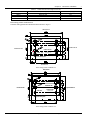
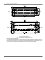


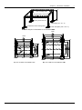
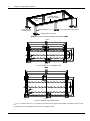


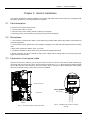

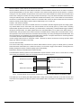

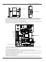

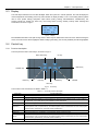

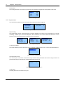
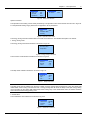

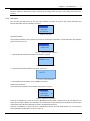


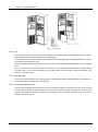
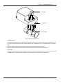


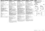
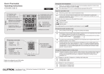


![特長など[PDF]](http://vs1.manualzilla.com/store/data/006533751_2-ccb7b66d18eb674acf28c93e1b51fc82-150x150.png)