1
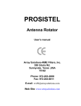
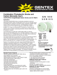
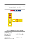
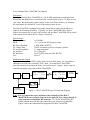
Array Solutions Bias-T MASTER User Manual
Description
The Array Solutions Bias-T MASTER is a 1.8-54 MHz stand-alone weatherproof unit
that permits the application or extraction of DC control signals of up to 1.5 amps on your
coax cable. By inserting the control voltage on the coax cable feed-line, you eliminate
the requirement for external DC wires for powering remote devices.
The Bias-T MASTER weatherproof assembly means that it can be placed indoors or
outdoors for maximum flexibility. Typically, one Bias-T MASTER will be placed
indoors for inserting DC on your coax feed-line, and one Bias-T MASTER will be placed
at the remote device where the DC voltage is extracted.
Specifications
Frequency Range:
SWR:
RF Power Handling:
DC voltage limit:
DC current capability:
DC Interface:
RF Interfaces:
Size:
1.8-54 MHz
<1.1:1 across the full frequency range
1.5KW SSB/CW/RTTY
50VDC maximum, positive or negative polarity
1.5 amps maximum
2.1x5.5mm jack
SO-239 UHF connectors (RF, RF+DC)
4x4x2.5”
Installation and Control
Typically one Bias-T MASTER will be located in your shack where it is convenient to
attach the coax feed and a switched 12VDC input. A second Bias-T MASTER is
typically remotely located near the device you wish to power. Figure 1 shows a typical
connection diagram using a pair of Bias-T MASTERs.
XCVR
AMP
Bias-T MASTER
RF ONLY
RF +DC
DC IN/OUT
DC IN
Bias-T MASTER
RF +DC
RF ONLY
Remote
Autotuner
DC IN/OUT
DC IN
DC OUT
• •
Pwr Control
+13.8VDC
Power Supply
Figure 1 – Bias-T MASTER Typical Connection Diagram
Note: It is very important to pay attention to the orientation of the Bias-T
MASTER in your system so that you do not apply DC bias voltage directly to
your transceiver or amplifier RF connector. I.e., the DC-blocked side (RF
ONLY) should always be the side connected to your transceiver or amplifier.
Figure 2 shows the connection/flow diagram of the Bias-T MASTER.
RF ONLY
DC IN/OUT
1.5A MAX
WX0B
BIAS-T
MASTER
ARRAY SOLUTIONS
160-2 MTR
Full Legal Limit
RF + DC
Figure 2: Bias-T MASTER Cover Label
Depending on your powering requirements, you may wish to apply either positive or
negative voltage to the Bias-T MASTER. This may be desirable for providing control for
up to a 3-way remote RF switch (plus, zero, and minus voltages for control). However, if
a negative control voltage is used, it MUST be derived from an isolated DC source where
the negative lead of the isolated source does not connect to the common station ground.
The use of a “wall wart” type of power source is perfect for this application.
Warning: Always ensure that your control voltage polarity is compatible with the
requirements of your remote device. Applying the incorrect polarity could
damage a remote auto-tuner or other device.
Warning: Always verify that there are no items on the coax feed-line which could cause
a DC short or very low impedance on the coax line. Such items would include
baluns or remote switches that ground the coax when not in use. A DC low
impedance or short on the coax will draw excess current through the Bias-T
MASTER and may damage the inductors in the Bias-T MASTER.
For a power control switch, you may wish to use one position of an Array Solutions
RatPAK controller, an Array Solutions Power Control switch, or you may wish to build
your own switch assembly.
Array Solutions Power Control Switch
The Array Solutions Power Control Switch houses the switch control function in a
convenient package. Two cables enter the rear of the switch assembly: 1) A 3-foot DC
input wire with stripped and tinned ends for attaching to your connector of choice, and 2)
A 5-foot cable terminated with a 2.1x5.5mm DC connector that plugs directly into the
Bias-T MASTER. Double-sided tape is provided so that the Power Control Switch may
be conveniently and firmly mounted at your operating position.
Array Solutions Power Control Switch