1
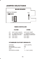
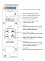
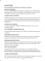
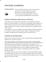
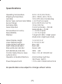
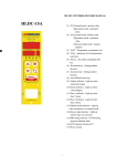
MICROPROCESSOR-BASED TEMPERATURE CONTROLLER
DUAL DIGITAL DISPLAY INDICATIING
DUAL TYPE THERMOCOUPLE SENSOR
HLDC-15 & HLDC-10 USER MANUAL
HOT RUNNER TEMPERATURE CONTROLLER
LKMHEATLOCK CO. LTD
HEAD OFFICE ADDRESS:
2/F., Cheung Kong Electronic
Building 4 Hing Yip Steet,
Kwun Tong,HongKong
TEL:(852)2341 2321
FAX:(852)2343 0990
E-MAIL :[email protected]
ADRESS IN CHINA:
Qiao Li Lnd.Area,Chang Ping,
DongGuan Guangdong,China
TEL:(86)0769-333 0020
FAX:(86)0769-393 9020
CAUTION
Never insert or remove a controller from a mainframe with the AC power on.
Hazardous potentials exist on components inside the mainframe and controller.
Always disconnect AC power to the mainframe when servicing ! Because these
temperature controls or associated equipment may not always fail safe, an
approved temperature and/or pressure safety control should be used for safe
operation.
GENERAL DESCRIPTION
The Series zone temperature controller is a PID-controlled instrument
specifically designed for runnerless (hot runner) plastic injection molding
applications. The controller is self-adjusting and capable of maintaining a very
high degree of temperature accuracy over a wide rage of operating conditions.
Simplified controls and the use of status indicators allow the operator to make
adjustments easily. The status display also provides visual indication of normal
or abnormal operating conditions existing in both the controller and/or load.
INSTALLATION
Set jumper configuration to desired operation (see jumper table). To install the
controller in a mainframe, release the locking device on the lower edge of the
unit by pulling the plunger gently away from the panel. Align the upper and lower
edges of the controller printed circuit board with the respective card guides on the
mainframe and slide the unit all the way into the mainframe until the rear
connector is completely engaged. Lock the controller into the frame by
depressing the plunger on the locking device.
Safety Warning
In addition to presenting a potential fire hazard , high voltage and high temperature
can damage equipment and cause severe injury or death.
When installing or using this instrument, follow all instructions carefully and use
approved safety controls (high limit, etc.). Only suitably trained personnel should
perform electrical wiring of connections.
Do not locate this instrument electrical where it may be subjected to excessive
shock, vibration, dirt, moisture, oil, or other liquids.
Safe operating temperature rang is 32 to 131 F (0 to 55 c ) .
(1)
JUMPER SELECTIONS
MAIN BOARD
DISPLAY BOARD
TOP
JP5
JP4
JP3
JP2
JP1
J9
WHEN INSTALLED
CLOSE
JP1
JP2
JP3
JP4
JP5
OPEN
SOFT START ALWAYS
"K" THERMOCOUPLE
DEGREES CELSIUS
NOT USED
NOT USED
AUTO SOFT START
"J" THERMOCOUPLE
DEGREES FAHRENHEIT
NOT USED
NOT USED
STANDARD FACTORY DEFAULTS
392 F (200 c )
DIS
13
7
+/- 33 F (20 c )
SETPOINT
AUTOTUNE
PROPORTIONAL BAND
RATE
DEVIATION ALARMS
(2)
INTRODUCTION
Thank you for choosing this Control. Congratulation on your purchase.
Used properly, this precision instrument will provide you with many years of
trouble-free and productive service.
The Series zone controllers offer many advanced features designed to
increase productivity and ensure fast, accurate and repeatable mold temperature
control.
--> Compatible with all G units and all existing Hot Runner Controls for easy
retrofit/replacement. ** (G Is Registered Trademark Of The DME CO. )
--> Simultaneous display of both process/setpoint temperature and process
temperature/percent power output or Heater current.
--> Autotuning independently adjusts zone control characteristics.
--> Built-in diagnostics alert operator to fault conditions.
--> AdjCompStep circuitry provides for safe heater warm-up through
gradual phase-angle fired voltage control (Soft Start).
PRODUCT DESCRIPTION
The Zone is a microcontroller-based "Hot-Runner" family control module
that provides temperature control and operator interface function. It controls
one temperature zone by sensing a J or K thermocouple (see jumper table).
The Zone operator input is via a 4-button keypad. The controller has two
displays comprised of seven-segment LED's. The upper display is a three
character display and the lower display is a four character display. Additionally
the unit has 3 discrete LED indicators to indicate system status.
The Controller consists of two electronics boards (Microcontroller and Display),
a triac /heat-sink assembly, and a front-panel assembly. It is physically and
electrically compatible with the existing other brands mainframe system.
The Zone is intended for use in an industrial environment by both technical
and nontechnical personnel. With this in mind, the Controller hardware and
software are designed for straightforward use with a high level of fault tolerance.
(3)
ENTERING AND CHANGING PARAMETER VALUES
The Parameter menu contains two items. Enter the menu by holding down
the DISPLAY key for three seconds. Exit the menu by holding down the
DISPLAY key for three seconds.
PID.
(2) Par.
(1)
Parameter Menu.
Parameter Menu.
-->To select next item in menu use the DISPLAY key.
The PID menu contains three items.
1). Pb
2). rAte
3). A.tun
Proportional Band
Tacking integral
Autotune Operation
(On/OFF)
-->To adjust parameters use the up or down keys.
-->To select next item in menu use the MODE key.
PROPORTIONAL BANDWIDTH
This item is accessible within the Menu. This PID control parameter is
adjustable from 0.1 to 999 F / 537 c
RATE
This item is accessible within the Menu. This PID control parameter is
adjustable from 0.0 to 999.
AUTOTUNE
On
ENABLE: Tunes every time power is applied.
OFF
DISABLE: Uses currently stored PID values.
The Par. menu contains two items.
1). LPb.t
Loop Break Time
This item is accessible within the Menu. This parameter is adjustable OFF
or from 10 to 999 seconds.
2). HT.SU
Heater Save Temperature
This item is accessible within the Menu. This parameter is adjustable OFF
or from 1 to 999 F / 537 c heater limited temperature.
(5)
Modes of Operation
Manual Mode
To switch to Manual Mode from Auto Mode, press the Mode key until the
"Manual" LED illuminates. This mode allows the operator to adjust the
Manual Output Percentage (0 to 100%) by pressing the UP/DOWN arrow keys.
There are two different parameters that can be viewed on the lower display
while in MANUAL mode. Pressing the DISPLAY key will toggle between them.
1. Manual Control Output percent: display followed by "P" (modifiable by user)
2. Measured Heater Current (display followed by "A")
AUTO MODE
To select Auto Mode, press the MODE key until the manual LED turns off.
This mode allows the operator to adjust the Setpoint temperature value by
pressing the UP/DOWN arrow keys.
There are three different parameters that can be viewed on the lower display
while in Auto Mode. Pressing the DISPLAY key will toggle between them.
1). Setpoint value (modifiable by user)
2). Output Percent (display followed by "P")
3). Measured Heater Current (display followed by "A")
(6)
FUNCTIONS
The controller provides the following functions:
SENSOR SAMPLING
A "J "or " K " (OPTIONAL) thermocouple is sampled using a 16-bit dual-slope
integrating A/D converter. Input voltages corresponding to temperatures from
32 to 999 F (0 to 537 c ) are processed with a resolution of 1 F ( c )
CLOSED-LOOP CONTROL
A PID control algorithm is used to adjust the amount of power delivered to the
load. The Proportional Band and Derivative parameters are individually and
directly adjustable. The Integral parameter tracks the Derivative parameter by
a fixed ratio.
OPEN-LOOP CONTROL
In open-loop (MANUAL CONTROL MODE),the operator is able to set the
output percentage.
ADJCOMPSTEP (HEATER BAKE-OUT)
Graduated phase-angle activation of the TRIAC is provided for drying heaters
on startup.
L00P-BREAK PROTECTION
Software will monitor the response of the system to changes in the output for
the purpose of detecting a control loop break. Display will read ("Er.01").
TEMPERATURE INDICATION
Actual process temperature is indicated on the Process Display (upper display).
Units ( F or c ) for this display are determined by a jumper (see page 2.) and
displayed on the lower display.
HEAT ON INDICATION
A single Blue LED is lit whenever the output is on. For additional output
state information, the operator will also be given the ability to directly monitor
the heater output percentage form the front panel's lower display.(see page 4.)
CURRENT MONITORING
The Controller is capable of monitoring and displaying the average current being
delivered to the load. The display is in 0.1 ampere increments.
(7)
FUNCTIONS (CONTINUED)
MANUAL CONTROL MODE
AUTO/MANUAL has easy accessibility from the front panel. Pressing the
"MODE" Key until the LED adjacent to "MANUAL" legend is illuminated will
cause manual control to begin. Manual Control is also activated at zero percent
when input error conditions arise and under these circumstances is activated
automatically regardless of the "MODE" key Enable state. The initial control
percent, established when manual control is activated, is dependent upon the
cause of activation. When entered normally because of operator actions, a
bumpless transfer is attempted. Pressing the "MODE" Key again (when in
manual mode) returns the control to automatic mode.
AdjCompStep/BAKE OUT/SOFT START
Gradually applying power to the heaters extends the life of the heaters and the
mold. Phase angle firing is used to implement the AdjCompStep feature. The
AdjCompStep will last for 5 minutes or until the temperature reaches 221 F.
AdjCompStep is a self-terminating feature but the operator may also terminate
it by pressing the MODE key.
AUTOTUNE
The tune operation will follow AdjCompStep. The tuner looks for stability in the
process temperature before it proceeds. If system stability cannot be achieved
within a fixed time period then the tune process will terminate. The operator
has the ability to terminate Autotuner execution by pressing the MODE key while
the Autotuner is active. During autotuning, the display alternately flashes "A.tu."
and the process value.
NORMAL CONTROL MODE (AUTO)
The control algorithm used for Normal control MODE is PID. The rate and
proportional band parameters appear in the menu system. The reset parameter
is always set to a value equal to five times the rate. The Controller has a fixed
cycle time of 100 ms (10Hz).
BUMPLESS TRANSFER
The Controller employs an intelligent bumpless transfer. When the process is
within five degrees of setpoint, the controller periodically records the output
percent necessary to maintain setpoint. When an operator initiated transition to
Manual Control occurs, the recorded output percentage is used.
(8)
FUNCTIONS (CONTINUED)
CURRENT MONITOR/ OUTPUT FAILURE DETECTION
The Current Monitor processor continually monitors heater current readings to
insure that they correlate with output activity.
If the output device signal (HEAT) is off and a current flow is detected then the
processor will post a triac short error, the Lower Display will toggle flash "Er.02"
error message, the Alarm LED will light, all other indicators are set off, and
all control processing will terminate.
If the output device is on but no current flow is detected then the processor will
post a bad heater error, the Lower Display will toggle flash "Er.03" error message,
the Alarm LED will light, all other indicators are set off, and all control
processing will terminate.
If either of these error conditions is detected, the OPTIONAL Power Interrupt
Relay provided by the hardware will open to interrupt power between the
TRIAC and the heater.
There is no automatic recovery from either of these problems. Once detected
and posted, power to the unit must be cycled for control processing to resume.
SENSOR ERROR DETECTION
When a sensor error is detected, the upper display will toggle between "TC" and
the cause of the thermocouple error: "r.tc." if the thermocouple is reversed,
"o.tc." if the thermocouple is open. The alarm LED will light, and the output
will turn off.
NORMAL OPERATING MODE
The following summarizes key functionality within Normal Operating MODE:
Pressed briefly, this key indexes to the next available
lower display item. Pressed for an extended time
(three seconds), menu system entry will occur.
UPARROW
This key will increment the current value of the item
presented is one that can be incremented. A setpoint
value is an example of a lower display item which
can be incremented. The measured Heater Current
value is an example of a lower display item which
cannot be incremented.
(9)
FUNCTIONS (CONTINUED)
DOWN ARROW This key will decrement the current value of the item
presented on the lower display when the item
presented is one that can be decremented.
This key will terminate AUTOTUNE or Soft Start
or will change the AUTO/MANUAL mode selection.
NORMAL OPERATING MODE DISPLAY FUNCTIONS
In the absence of any special circumstances or error conditions, the upper
display (3-character display) of the Controller is dedicated to the presentation of
the Process Value when the unit is in Normal Operating MODE. The Process
Value is displayed in accordance with the temperature scale established by the
"Units" jumper.
In the absence of any error conditions, the lower display (4 character display) of
the Controller is used to present a variety of items. The operator can index
through the available items with brief presses of the DISPLAY key.
AUTOTUNE ACTIVE INDICATOR
Whenever the Autotune Process is active, the upper display will toggle between
Autotune (A.tu.) and Process Value.
The Autotune process can terminate itself for two reasons. Self-termination
occurs because the process has either completed or an error has been detected.
When the process has completed, the Autotune Active Indicator (A.tu.) is
removed and the display reverts to a steady display of the process Value. When
the process self-terminates due to an error condition the Autotune Active
Indicator will toggle with a mnemonic, indicating the specific error condition
that has occurred.
The Autotune process can also be terminated by pressing the MODE key while
the Autotune process is active. The unit will go directly to Normal Control Mode,
the Autotune Active Indicator (A.tu.) is removed and the display reverts to a steady
display of the Process Value.
(10)
Specifications
Operating Temperature
Shipping Temperature
Humidity
Sensor Type (Jumper Selectable)
Sensor Range
Sampling Rate
Noise Rejection
Temperature Accuracy
Repeatability
Displays
32 to 131 F (0 to 55 c )
-40 to 158 F (-40 to 70 c )
10 to 95% Non-Condensing
J or K Thermocouple
32 to 999 F (0 to 537 c )
10 Hz (100 ms)
Common Mode> 100 dB
Series Mode> 70 dB
+/- 0.3% of span.
+/- 0.1% of span.
7-Segment LEDs; 3-digit upper
(Red) and 4-digit lower (Red)
Upper Display Height
Lower Display Height
Output Status Indication
Alarm Status Indication
Manual Mode Indicator
Soft-Start Mode Indicator
Control Output Device Type
optional 30 A
14.2 mm/ 0.4"
9.15 mm/ 0.36"
Blue LED
Red LED
Green LED
ORG LED
Triac, 15 A at 120/240 Vac
Operator Activation/Interface
4 Momentary Switches,
16A Power Switch
115 to 240 V 50/60 Hz Nominal
Power Requirements
All specifications are subject to change without notice.
(11)
ERROR CODE DSIPLAY
ERROR CODE
DESCRIPTION
Er.01
Er.02
o.tc.
r.tc.
Er.03
Loop Break Down
Output Short
Open Thermocouple
Reverse Thermocouple
Open Heater
(Display
(Display
(Display
(Display
Flash)
Flash)
Flash)
Flash)
Manual End
(12)