1
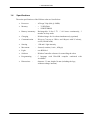
Kilobot
User manual
Version 1.3
AUGUST 2013
Documentation Author
Julien Tharin
K-Team S.A.
Z.I des Plans-Praz
CH-1337 Vallorbe
Switzerland
Email: [email protected]
Url: www.k-team.com
Documentation version
Version
1.0
1.1
1.2
1.3
Date
09.12.2011
15.03.2012
13.07.2012
12.08.2013
Author
J. Tharin
J. Tharin
F.Lambercy
J. Tharin
Description
First draft
Updated for new Kilobots version
Colour of OHC led corrected (chapter 4.2.3)
Usb cable connection (only one, chapter 4.2.3); added V-REP simulation
Trademark Acknowledgements:
IBM PC
Macintosh
SUN Sparc-Station
LabVIEW
Matlab
Webots
Logitech
Gumstix
Khepera
V-REP
:
:
:
:
:
:
:
:
:
:
International Business Machines Corp.
Apple Corp.
SUN Microsystems Corp.
National Instruments Corp.
MathWorks Corp.
Cyberbotics Ltd
Logitech Int. SA
Gumstix Inc.
K-Team SA
Coppelia Robotics
LEGAL NOTICE:
•
•
•
The contents of this manual are subject to change without notice
All efforts have been made to ensure the accuracy of the content of this manual.
However, should any error be detected, please inform K-Team.
The above notwithstanding, K-Team can assume no responsibility for any error in this
manual.
TABLE OF CONTENTS
1.
INTRODUCTION ................................................................................................. 1
1.1
1.2
1.3
1.4
2.
UNPACKING AND INSPECTION..................................................................... 4
2.1
2.2
3.
HOW TO USE THIS HANDBOOK ..................................................................................... 1
SAFETY PRECAUTIONS ................................................................................................. 2
RECYCLING ................................................................................................................. 2
SPECIFICATIONS .......................................................................................................... 3
PACKAGE CONTENTS................................................................................................... 4
INSPECTION ................................................................................................................. 5
DESCRIPTION ..................................................................................................... 6
3.1
OVERVIEW .................................................................................................................. 6
3.1.1
KILOBOT ROBOT .................................................................................................. 6
3.1.2
OVERHEAD CONTROLLER (OHC) ........................................................................ 7
3.2
KILOBOT HARDWARE .................................................................................................. 8
4.
USAGE ................................................................................................................. 10
4.1
REQUIRED HARDWARE / SOFTWARE .......................................................................... 10
4.1.1
REQUIRED HARDWARE: ..................................................................................... 10
4.1.2
REQUIRED SOFTWARE: ...................................................................................... 10
4.2
INSTALLATION........................................................................................................... 12
4.2.1
INSTALL THE SOFTWARE.................................................................................... 12
4.2.2
OVERHEAD CONTROLLER (OHC) SOFTWARE INSTALLATION ........................... 12
4.2.3
OVERHEAD CONTROLLER (OHC) HARDWARE INSTALLATION .......................... 13
4.2.4
KILOBOT BOOTLOADER PROGRAMMING ............................................................ 14
4.3
USAGE ....................................................................................................................... 17
4.3.1
PROGRAMMING A KILOBOT GROUP WITH A NEW PROGRAM ............................... 17
4.3.2
OHC USE .......................................................................................................... 18
4.3.3
CHARGER .......................................................................................................... 21
4.3.4
DEBUGGING ...................................................................................................... 22
4.3.5
KILOBOTS API .................................................................................................. 23
4.3.6
MOTORS CALIBRATION ...................................................................................... 26
4.3.7
SIMULATION ...................................................................................................... 28
5.
ANNEXES ............................................................................................................ 30
5.1
EXAMPLES OF SOURCE CODE ..................................................................................... 30
5.1.1
TRANSMITS DATA TO NEIGHBORS, AND BLINKS LED WHEN THE MESSAGE IS
RECEIVED: ......................................................................................................................... 30
5.1.2
NON-BLOCKING TIMED MOVEMENT:.................................................................. 30
5.1.3
RANDOM MOVE IN SEE NEIGHBORS, STOP ELSE .................................................. 32
6.
WARRANTY ....................................................................................................... 34
1. INTRODUCTION
1.
INTRODUCTION
Thank you for buying Kilobot robots!
Kilobots are low cost robots designed at Harvard University's Self-Organizing Systems
Research Lab http://www.eecs.harvard.edu/ssr. The robots are designed to make testing
collective algorithms on hundreds or thousands of robots accessible to robotics researchers.
Though the Kilobots are low-cost, they maintain abilities similar to other collective robots.
These abilities include differential drive locomotion, on-board computation power, neighbor-toneighbor communication, neighbor-to neighbor distance sensing, and ambient light sensing.
Additionally they are designed to operate such that no robot requires any individual attention by
a human operator. This makes controlling a group of Kilobots easy, whether there are 10 or 1000
in the group.
You can find more information directly on the designer website:
http://www.eecs.harvard.edu/ssr/projects/progSA/kilobot.html
1.1
How to use this handbook
This handbook introduces the Kilobot and its various operating modes. For a quick start,
jump to chapter 4 ”USAGE”.
If this handbook does not answer one of the problems you wish to solve, please consult
the K-Team web site (http://www.k-team.com) and especially the Forum and the FAQs.
•
Unpacking and Inspection :
Kilobot package description and first use.
•
Description
:
Kilobot description.
•
Usage
:
Kilobot usage descriptions.
•
Annexes
:
Examples of source code.
Kilobot User Manual
1
1. INTRODUCTION
1.2
Safety precautions
Here are some recommendations on how to correctly use the Kilobot:
1.3
•
Keep the board away from wet area. Contact with water could cause malfunction
and/or breakdown.
•
Store your board in a stable position. This will avoid the risks of falling, which
could break it or cause damage to a person.
•
Do not plug any connectors while the board is powered on. To avoid any damage,
make all connections when the board power is off.
•
Keep the board away of conducting materials. To avoid any short-circuit and
damage to the robots, avoid contact with metallic lonely wires and other conducting
materials.
Recycling
Think about the end of life of your product! Parts of the board can be recycled and it is
important to do so. By recycling you can help to create a cleaner and safer environment for
generations to come. For those reasons please take care to the recycling of your product at the
end of its life cycle, for instance sending back the product to the manufacturer or to your local
dealer.
Thanks for your contribution to a cleaner environment!
2
Kilobot User Manual
1. INTRODUCTION
1.4
Specifications
The main specifications of the Kilobot robot are listed below:
•
Processor
:
ATmega 328p (8bit @ 8MHz)
•
Memory
:
○ 32 KB Flash
○ 1KB EEPROM
•
Battery/ autonomy:
Rechargeable Li-Ion 3.7V / 3-10 hours continuously, 3
months in sleep mode
•
Charging
:
Kilobot charger for 10 robots simultaneously (optional)
•
Communication
:
IR (up to 7cm, up to 32kb/s and 1kbyte/s with 25 robots),
serial (256000 baud)
•
Sensing
:
1 IR and 1 light intensity
•
Movement
:
forward, rotation (1cm/s , 45deg/s)
•
Light
:
one RGB led
•
Software
:
Kilobot Controller software for controlling the robot
•
Programming
:
C language with WinAVR compiler combined with
AvrStudio
•
Dimensions
:
diameter: 33 mm, height 34 mm (including the legs,
without recharge antenna).
Kilobot User Manual
3
2. UNPACKING AND INSPECTION
2.
UNPACKING AND INSPECTION
2.1
Package Contents
They are 3 different packages sold separately. They are containing the following items:
•
The robot package:
1 CD-ROM*
10 Kilobot robots
•
The overhead controller package:
1 overhead controller
1 CD-ROM*
3 cables (1 usb, a 6-wire cable and a 2–wire cable)
•
The charger package:
1 charger
1 transformer
1 CD ROM*
* If multiple packages are ordered together, only one CD-ROM will be shipped.
4
Kilobot User Manual
2. UNPACKING AND INSPECTION
2.2
Inspection
The material should be checked after unpacking.
For the Kilobots robots, check that their legs are not bended. The charging tab also must
not be bended. The jumper and the battery should be present (see figure 3.1). The battery
should be plugged with the negative on top (opposite of the battery holder +/- marks).
For the Overhead controller, check that the LEDS are not bended or broken. The jumper
for firmware programming should be present (see figure 3.2).
Kilobot User Manual
5
3. DESCRIPTION
3.
DESCRIPTION
3.1
Overview
3.1.1 Kilobot robot
An overview of the Kilobot hardware is depicted in the Figure 3.1. The locations of various
key elements are indicated for later references.
⑧
⑪
①
③
⑦
ov
④
⑨
⑩
③
⑥
⑤
②
⑪
⑪
⑪
⑪
Figure 3.1: Kilobot overview
① 3.7-Volt Battery (- up, + down)
⑦ Direct programming socket
② Power jumper
⑧ Charging Tab
③ Vibration motors
⑨ IR Transmitter
④ LED (Red/Green/Blue)
⑩ IR Receiver
⑤ Ambient light sensor
⑪ Robot leg
⑥ Serial output header
6
Kilobot User Manual
3. DESCRIPTION
3.1.2 Overhead controller (OHC)
An overview of the Kilobot Overhead controller (OHC) is depicted in the Figure 3.1. The
locations of various key elements are indicated for later references.
⑧
⑧
⑧
①
⑧
⑧
②
⑥
⑥
⑧
③
⑦
ov
⑤
⑧
④
⑧
⑧
⑧
Figure 3.2: Overhead controller overview
① Overhead controller board
⑤ Firmware programming jumper
② Connector for USB cable
⑥ Diode for OHC connection test
③ Connector for debug cable
⑦ Power on LED
④ Connector for firmware programming
⑧ IR LED
Kilobot User Manual
7
3. DESCRIPTION
3.2
Kilobot Hardware
The hardware of the Kilobot is described thereafter.
The robot has a microcontroller ATmega 328p (8bit @ 8MHz) as CPU. It contains these
following types of memory:
○ 32 KB Flash used for both user program and bootloader
○ 1KB EEPROM for storing calibration values and other nonvolatile data and 2KB SRAM.
Its other features are described in detail below:
•
Battery
:
Rechargeable Li-Ion 3.7V, for a 3 months autonomy in
sleep mode. Each Kilobot has a built-in charger circuit,
which charges the onboard battery when +6 volts is applied
to any of the legs, and GND is applied to the charging tab.
•
Charging
:
Kilobot charger (optional)
•
Communication
:
Kilobots can communicate with neighbors up to 7 cm away
by reflecting infrared (IR) light off the ground surface.
•
Sensing
:
○ When receiving a message, distance to the transmitting
Kilobot can be determined using received signal
strength. The distance depends on the surface used as
the light intensity is used to compute the value.
○ The brightness of the ambient light shining on a Kilobot
can be detected.
○ A Kilobot can sense its own battery voltage.
•
8
Movement
:
Each Kilobot has 2 vibration motors, which are
independently controllable, allowing for differential drive
of the robot. Each motor can be set to 255 different power
levels.
Kilobot User Manual
3. DESCRIPTION
•
Light
:
Each Kilobot has a red/green/blue (RGB) LED pointed
upward, and each color has 3 levels of brightness control.
•
Software
:
The Kilobot Controller software is available for controlling
the controller board, sending program files to the robots and
controlling them.
•
Programming
:
For programming, the open source development software
WinAVR combined with AvrStudio from Amtel gives a C
programming environment. An API with basic functions
such as motor speed, led control, distance measurement,...
is available and some examples are provided.
•
Debug
:
A serial output header is available on each robot for
debugging via computer terminal.
Kilobot User Manual
9
4. USAGE
4.
USAGE
4.1
Required hardware / software
The required hardware and software to use the board and develop programs are described below.
4.1.1 Required hardware:
•
Computer with Microsoft Windows and an USB port (not included)
•
Kilobot robot
•
Over-head controller (OHC)
•
Kilobot charger
4.1.2 Required software:
Required files:
•
Microsoft .NET Framework 2.0 Service Pack 2
http://www.microsoft.com/en-us/download/details.aspx?id=1639
These files are included in the delivered from the CD_ROM:
10
•
The compiler WINAVR:
software\compiler\WinAVR-20100110-install.exe
•
The editor AVR Studio 4:
software\editor\avrstudio4.19setup.exe
•
Kilobot controller and programming skeleton project files (VERSION is the
version of the files):
software\source_code\KilobotController_VERSION.zip
This archive contains:
• dev/
development directory
• dev/default/
compiled object and program directory
• dev/KilobotSkeleton.aps AVR Studio editor project configuration
• dev/KilobotSkeleton.aws AVR Studio editor workspace file
Kilobot User Manual
4. USAGE
•
•
•
•
•
•
•
•
•
•
•
•
•
•
dev/KilobotSkeleton.c
source code skeleton where you start
programming
dev/ libkilobot.c
kilobot library source code
dev/ libkilobot.h
kilobot library source code header
FTDI32/
directory for 32 bit driver for USB driver
FTDI64/
directory for 64 bit driver for USB driver
STK500/
directory for Atmel AVR Flash
Controller.hex
controller normal firmware
KiloBot Controller.exe
Kilobot Controller program
KilobotFirstFirmware.hex robot first firmware
Kilobot_motor_cal.hex
robot calibration program
OHC_motor_cal.hex
controller "motor calibration" firmware
Program.hex
copied current robot program
Readme.txt
readme
RealTerm terminal for debugging:
software\terminal\Realterm_2.0.0.70_setup.exe
Kilobot User Manual
11
4. USAGE
4.2
Installation
The following sub-chapters explain the software and installations.
4.2.1 Install the software
1. Install WINAVR compiler if not already done.
2. Install also AVR Studio 4 editor.
If you did not install WINAVR in the default install directory (C:\WinAVR-20100110),
you will have to tell AVR studio where is the compiler and the maker:
In AVR Studio “Project” menu, select “Configuration Options” sub-menu and choose the
“Custom Option”. Under “External tools”, with the … button on the bottom right, select
for avr-gcc the file avr-gcc.exe in the WinAVR-20100110\bin directory and for make the
file make.exe in the directory WinAVR-20100110\utils\bin .
3. Decompress KilobotController_VERSION.zip in c:\
4.2.2 Overhead Controller (OHC) Software Installation
1. Open KilobotController.exe from c:\KilobotController.
2. In the Help menu of KilobotController.exe, select “Installation and programming” and
follow the instructions to install the software and drivers (Fig 4.1).
12
Kilobot User Manual
4. USAGE
Figure 4.1: OHC software
4.2.3 Overhead Controller (OHC) Hardware Installation
1. Check that the firmware jumper is plugged at the correct place (figure 4.6).
2. Connect the USB cable to the PC; the power LED of the OHC should turn green.
3. Run the KilobotController.exe program, and click the “Toggle LEDs” button to test that a
connection is made (Fig 4.2). This should blink the red LEDs on the controller.
Figure 4.2: OHC software buttons
Kilobot User Manual
13
4. USAGE
4.2.4 Kilobot bootloader programming
The Kilobot is delivered with a bootloader already installed. Therefore this step can be
SKIPPED. But If you would like to reinstall the bootloader or install a newer one, follow the
instructions below.
1. In AVR Studio, select Tools->ProgramAVR->Autoconnect .
2. In the window that pops up, under the program tab, in the flash category select the input
hex file to be KilobotFirstFirmware.hex.
3. Put the firmware programming jumper of the OHC in the “firmware mode” position and
connect the firmware cable (figure 4.3).
Figure 4.3:firmware cable and jumper in firmware mode
14
Kilobot User Manual
4. USAGE
4. Turn on the robot by adding the power jumper as shown in figure 4.4.
Figure 4.4: power jumper
5. Connect the AVRisp programmer to the robot as shown in figure 4.5. Make sure that the
programmer pins do not touch the motor on the back side. Gently press the program
cable to the side to ensure a good connection.
Figure 4.5: communication connector
Kilobot User Manual
15
4. USAGE
6. Set robot fuses: In Avr studio AVRISP programming window, go to the fuses tab. Select
only the following fuses: spien, EESAVE, BOOTSZ (boot flash size 2048 word, start
address =$3800) , SUT_CKSEL (int. RC Osc. 8 MHz; start-up time
PWRDWN/RESET: 6 CK/14CK +65 ms). This should result in the following fuse
values: extended=0xFF, high=0xD1, low=0xE2
7. In the Autoconnect pop-up window in AVRstudio, press program. It should take a few
seconds to program the robot, and the robot may vibrate.
8. Put the firmware programming jumper of the OHC in the back to the standard position.
Figure 4.6: firmware jumper: normal mode
16
Kilobot User Manual
4. USAGE
4.3
Usage
4.3.1 Programming a kilobot group with a new program
1. In c:\KilobotController\dev\ double-click on Kilobot.aps for opening the project
2. In KilobotSkeleton.c locate the following section
/////////////////////////////////////////////////////////////////////////////////////
//user program code goes here. this code needs to exit in a reasonable amount of time
//so the special message controller can also run
/////////////////////////////////////////////////////////////////////////////////////
3. Immediately after this is where the user code is written. Note that the user code should
not contain long blocking functions; otherwise the robot may not respond to the overhead
controller properly.
4. Once program is written, in AVRstudio select Build->build.
5. Run KilobotController.exe, click the button to browse for a program file as shown and
select the program [.hex] file you just built (located at c:\KilobotController\dev\
/default/KilobotSkeleton.hex).
Figure 4.7 : Kilobot Controller software
6. Press the “Program Flash” button to program the OHC (a black window will pop up).
7. Place ALL Kilobot robot in PAUSE mode (LED flashing yellow) underneath the OHC,
and press the “Bootload” button in KilobotController.exe. The Kilobot will first quickly
flash red->green->blue, to indicate it is now in the PROGRAMMING mode. Within 5
seconds, the LED will begin to flash blue and continue flashing while it is receiving the
new program. Once the LED has stopped flashing blue and switch to the flashing yellow
Kilobot User Manual
17
4. USAGE
of pause mode (approximately 30 seconds), press the “Stop” button in
KilobotController.exe.
8. To run the program on the robot, press the “Run” button in KilobotController.exe. The
new program should execute.
9. Press the “Pause” button in KilobotController.exe to stop the program. (Note: the robot
needs to be in pause mode before programming can begin).
You can find in annex 5.1 examples of source code.
4.3.2 OHC Use
System Setup
Kilobots should be operated on a smooth, flat surface to ensure proper robot mobility. To
aid communication, the surface should be glossy or reflective. A mirror or dry-erase whiteboard
oriented horizontally is recommended.
The overhead controller should be hung above the Kilobots at a distance of about one
meter. The robots beneath the OHC in a about a one meter diameter region will be able to receive
communication from the OHC as shown in figure 4.8.
Figure 4.8: System setup
18
Kilobot User Manual
4. USAGE
Overhead Controller (OHC) Interface Overview
Figure 4.9: Programming Panel
1. Program file: browse for the compiled Kilobot user program [.hex] file to be sent to the
Kilobots (usually in c:\KilobotController\dev\default).
2. Program Flash: send the program and controller files to the OHC.
Figure 4.10: Connection Status
You can see if the OHC is connected to the pc or not (fig 4.10).
Below in figure 4.11 is the Button Panel with a description of the buttons functionality.
Kilobot User Manual
19
4. USAGE
Figure 4.11: Button Panel
1. Bootload: transmit the kilobot user program from the OHC to the Kilobots, which takes
about 30 seconds. Ensure all robots are in pause mode before bootloading.
2. Sleep: put Kilobots in low-power SLEEP mode. They will wake up briefly every 60
seconds to check if a wakeup message is being sent. The robots conserve energy in this
mode and can stay in sleep for months without recharging.
3. Pause: put Kilobots in idle PAUSE mode, and is also used to prepares robots to be
reprogrammed.
4. Run: initiates Kilobots user program.
5. Battery Voltage: instructs Kilobots to indicate their battery voltage through the LED.
where green indicates a battery voltage over 4V, blue indicates a voltage between 3.75
and 4, yellow indicates a voltage between 3.5 and 3.75, and red indicates a voltage under
3.5 volts .
6. Bootloader msg: sends a message for all robots to exit their program and jump to the
bootloader.
7. Wakeup: take Kilobots out of low-power SLEEP mode. This message will transmit untill
stop is pressed. It will take a minute or two for all the robots to wake up.
8. Reset: restarts the Kilobot program.
9. Charge: instructs Kilobots to enter CHARGE mode for battery recharging. The robots
will stop the user program and blink red if they are actively charging, if not, the RGB led
will turn off.
10. Toggle LEDs: flashes the LEDs on the OHC.
11. Stop: stops whatever the OHC is doing. This can be used to stop functions that are
continuous such as wakeup or bootloading.
20
Kilobot User Manual
4. USAGE
4.3.3 Charger
A charger for up to 10 Kilobots is available as an optional item.
1. Put the Kilobots charger on a flat surface, having the bar with the red indicator below and
the black above.
WARNING: if the color position is not respected, that will not work and may damage
the charger or the robots.
2. Plug the Kilobots charger transformer to the charger and to a power socket. Pay attention
to the polarization (+ outside, - inside).
WARNING: if the polarization is not respected, that will not work and may damage the
charger or the robots.
3. Switch the Kilobots on (put the power jumper as in figure 4.4).
4. Pay attention to respect the bar side and the cable polarization as explained above in 1)
and 2), Then hang the Kilobots as specified in the figure below. The bar with the red
indicator is in contacts of the legs of the robots and is the positive.
5. With the Kilobot Controller, push the Charge button. The robot will stop the current
program and enter in charge mode indicated by a blinking red. If the charge is done, the
RGB led will turn off.
6. After the charge is finished, you can remove the robots from the charger and use them as
normal with the Kilobot Controller (push the Pause button to go back to pause mode).
cable to 6V charger
(+ outside, - inside)
connector of the 6V
cable
(+ outside, - inside)
red indicator indicating lower bar
Figure 4.12: Kilobots on charger
Kilobot User Manual
21
4. USAGE
4.3.4 Debugging
With the kprinti() and kprints() functions, you can get a feedback from the robot. You
must connect the robot to the OHC with the 2-wire cable, respecting the polarity on the robot as
shown in the figure below (see figures 3.1 and 3.2 for the connectors place).
black
red
debug cable
Figure 4.13 Debug settings
1. Install Realterm, a terminal that can use alternate baud rates.
2. Launch your program with the “Run” button of the Kilobot Controller.
3. Close the Kilobot Controller if it is open.
4. Find the USB serial port number used by the OHC in the Device Manager of your
computer.
5. Connect Realterm to the number of the USB serial port found above with a baud rate of
256000.
22
Kilobot User Manual
4. USAGE
4.3.5 Kilobots API
The different functions specially developed for the Kilobots are explained below. Numerous
other functions and AVR-C programming examples can be found on the web.
•
set_motor(cw_motor,ccw_motor)
Set motor speed PWM values for motors between 0 (off) and 255 (full on) for cw_motor
and ccw_motor
Examples:
-
for moving forward: set_motor(cw_in_straight, ccw_in_straight);
for turning right: set_motor(cw_in_place, 0);
for turning left: set_motor(0, ccw_in_place);
set_motor(100, 100);
Note that there are 4 calibration values used with the motors
cw_in_place: value for cw motor to turn the robot cw in place (note: ccw motor
should be off)
ccw_in_place: value for ccw motor to turn the robot ccw in place (note: cw motor
should be off)
cw_in_straight: value for the cw motor to move the robot in the forward direction
ccw_in_straight: value for the ccw motor to move the robot in the forward direction
•
_delay_ms(x)
Busy wait for x milliseconds, interrupts can still trigger
//max value for milliseconds = 4000
Example:
_delay_ms(250);
•
set_color(r,g,b)
Set LED color, values can be from 0(off)-3(brightest)
Example:
set_color(1,1,1);
•
kprinti(int)
Print integer over serial port - be careful can effect timing!
Example:
kprinti(12);
•
kprints(string)
Print string up to 10 characters - be careful, can effect timing!
Kilobot User Manual
23
4. USAGE
Example:
kprints("HelloWorld");
•
message_out(tx0,tx1,tx2)
Set message values to be sent over IR every .2 seconds, 3 bytes tx0,tx1,tx2
(tx2 lsb must not be used) .
Example:
message_out(0x01,0xFF,0xFE);
•
get_message()
Take oldest message off of rx buffer message. It is only new if message_rx[5]==1 !
If so, message is in message_rx[0] and message_rx[1]; distance to transmitting robot (in
mm) is in message_rx[3]. The distance depends on the surface used as the light intensity
is used to compute the value.
Example:
get_message();
if(message_rx[5]==1)
{
data=message_rx[0];
distance=message_rx[3];
}
•
enable_tx
to turn off the transmitter, set enable_tx = 0
to turn on the transmitter, set enable_tx = 1
Example:
if(Want_To_Transmit==TRUE)
enable_tx = 1;
else
enable_tx = 0;
•
measure_charge_status()
Measure if battery is charging, returns 0 if no, 1 if yes
Example:
if(measure_charge_status())
charging = TRUE;
else
charging = FALSE;
•
measure_voltage()
Measure battery voltage, returns voltage in .01 volt units
for example if 394 is returned, then the voltage is 3.94 volts
Example:
current_voltage = measure_voltage();
24
Kilobot User Manual
4. USAGE
•
get_ambient_light()
Returns the value of ambient light
note: will return -1 if there is an incoming message (which also uses a/d)
note: turns off interrupts for a short while to sample a/d
Example:
local_brightness = get_ambient_light();
Kilobot User Manual
25
4. USAGE
4.3.6 Motors calibration
If you see that the robot is no more moving forward and does not rotate well anymore,
you can try to recalibrate its motors with the instructions below. But as already said before, the
Kilobot should be operated on a smooth, flat surface to ensure proper robot mobility.
1. Upload the motors calibration receiver program Kilobot_motor_cal.hex to the robot.
2. Choose the calibration transmitter program OHC_motor_cal.hex to the OHC with the
advanced menu “Select alternative controller file” and push “Program flash button to
reprogram the Kilobot Controller in motor calibration mode (Figure 4.14).
3. In the OHC software, select the “Motor calibration” sub-menu of the advanced menu.
Figure 4.14: Advanced menu
4. Place the Kilobot under the OHC, and push the button "More cw" or "Less cw" to adjust
the calibration of the clock wise rotation for the robot.
Figure 4.15: Motors calibration
5. When clock wise rotation is good, click "More CCW" once. Now you can use the "more
CCW" and the "Less CCW" buttons to calibrate the robots CCW rotation.
26
Kilobot User Manual
4. USAGE
6. When CCW rotation is good, click the "More cw" button once. Now you can use the
"More CCW", "Less CCW", "More CW", "Less CW" buttons to adjust the robots straight
calibration value.
7. When the robots straight movement is good, click "Store values". The robot will store
calibration values in EEPROM, and then go to sleep. The motors are now calibrated.
WARNING: Don’t switch off the robot now otherwise it will go back to calibration mode
when rebooting.
8. When done, be sure to load Controller.hex back into the OHC with the Advanced menu
“Select alternative controller file”.
9. Push wake-up button on the OHC.
10. Program the robot with the KilobotFirstFirmware.hex or your program.
11. You can switch off the robot now or put it in sleep mode.
Kilobot User Manual
27
4. USAGE
4.3.7 Simulation
You can simulate the Kilobot robot with V-REP, a power physics simulator software. An
educational version is available for free at: http://www.coppeliarobotics.com/downloads.html
The Kilobot model is already available for V-REP inside the simulator.
All the functions explained in chapter 4.3.5 “Kilobots API” are implemented.
•
get_ambient_light() function is implemented only in the following because it takes 1.5
more time of simulation:
scene:
http://ftp.k-team.com/V-REP/models/Kilobot/scenes/Kilobots_light_intensity.ttt
model:
http://ftp.k-team.com/V-REP/models/Kilobot/models/Kilobot_light_intensity.ttm
•
For the _delay_ms(x) function, as it must be non-blocking, you need to implement it like
this for example _delay_ms(50): use a state variable (here substate).
substate=0
…
function user_prgm()
…
-- wait 50 ms:
if (substate==0) then
delay_start=simGetSimulationTime()
elseif (substate==1) then
if (_delay_ms(50)==1) then
-- waited
substate=0
----------------------- here put the following of your code
---------------------end
…
28
Kilobot User Manual
4. USAGE
You can find some V-REP scenes with Kilobot examples there:
http://ftp.k-team.com/V-REP/models/Kilobot/scenes
Kilobots_messages.ttt
:
5 robots move and display their distances to
each others with their led.
Kilobots_ messages.ttt
:
4 robots send messages to each other to
determinate the one that has the biggest id
number.
Kilobots_ around.ttt
:
robots move around other static robots, keeping
distance.
Kilobot User Manual
29
5. ANNEXES
5.
ANNEXES
5.1
Examples of source code
These examples of source code have different purposes described in there titles.
5.1.1 Transmits data to neighbors, and blinks led when the message is
received:
…
message_out(255,255,0);//set message to be sent over IR
enable_tx=1;//enable transmission of message every .2 seconds
//check for message
get_message();
if(message_rx[5]==1)//new message has been received
{
set_color(1,1,1);//turn RGB LED white
kprinti(message_rx[0]);//send first byte of received message over serial debug
cable
kprinti(message_rx[1]);//send second byte of received message over serial debug
cable
kprinti(message_rx[3]);//send measured distance from transmitting robot over
serial debug cable
kprints("
");
_delay_ms(10);//wait 10 ms
set_color(0,0,0);//turn RGB LED off
}
5.1.2 Non-blocking timed movement:
…
static int mode=0;//mode represents state
if(clock<40000)
{
//clockwise rotation
if(mode!=0)
{
30
Kilobot User Manual
5. ANNEXES
set_motor(0xa0,0);//spin up cw motor to overcome friction
_delay_ms(30);
set_motor(cw_in_place, 0);//set cw motor to calibrated value for good cw
rotation
mode=0;
}
}
else if(clock<80000)
{
if(mode!=1)
{
//counter clockwise rotation
set_motor(0,0xa0);//spin up ccw motor to overcome friction
_delay_ms(30);
set_motor(0, ccw_in_place);//set ccw motor to calibrated value for good
cw rotation
mode=1;
}
}
else if(clock<120000)
{
if(mode!=2)
{
//move forward
set_motor(0xa0,0xa0);//spin up both motors to overcome friction
_delay_ms(30);
set_motor(cw_in_straight, ccw_in_straight);//set both motor to calibrated
value for good forward movement
mode=2;
}
}
else if(clock<160000)
{
if(mode!=3)
{
set_motor(0x00,0x00);//turn off motors
mode=3;
}
}
else if(clock<200000)
{
mode=5;
clock=0;//reset clock to start cycle over agian
}
Kilobot User Manual
31
5. ANNEXES
5.1.3 Random move in see neighbors, stop else
static int one_time=0;
if(one_time==0)//if this is the start of the program, only run this if statement once
{
for(int i=0;i<30;i++)
randseed+=measure_voltage( );//generate some random sensor data
one_time=1;//indicate that the first time if statement has now run
srand(randseed);//seed random variable with some sensor data
}
static int neighbor=0;//1 if i've seen any neighbors, 0 if not
static int movement=0;//1 if moving, 0 if stopped
static int start_move=0;//1 if the movement has changed, 0 if not
//check to see if i have received any new messages, if so, then i have seen neighbors
get_message();
if(message_rx[5]==1)
neighbor=1;
//if i am currently not moving, and want to start moving
if(start_move==1)
{
if(movement==0)
{
set_motor(0xa0,0xa0);//spin up motors
_delay_ms(30);
set_motor(cw_in_straight, ccw_in_straight);//set to move straight
}
else if(movement==1)
{
set_motor(0, 0xa0);//spin up motor
_delay_ms(30);
set_motor(0, ccw_in_place);//set to move ccw
}
else
{
set_motor(0xa0,0);//spin up motor
_delay_ms(30);
set_motor(cw_in_place ,0);//set to move cw
}
start_move=2;//mark that i am currently moving
}
else if(start_move==0)//i do not want to move
{
set_motor(0,0); //stop motors
}
//every 2000 counts of clock, check to see if i've seen any neighbors
//if i have, there is a 20% chance i will change my movement (such as straight to ccw)
if(clock>2000)
{
32
Kilobot User Manual
5. ANNEXES
if((rand()%100)<20)//update robot movement 20% of the time
{
int rand_d=rand()%100;
if(rand_d<25)//if updating robot movement 25% of the time move ccw
{
if(movement!=1)
{
movement=1;
if(start_move==2)
start_move=1;
}
}
else if(rand_d<50)//if updating robot movement 25% of the time move cw
{
if(movement!=2)
{
movement=2;
if(start_move==2)
start_move=1;
}
}
else//if updating robot movement 50% of the time move straight
{
if(movement!=0)
{
movement=0;
if(start_move==2)
start_move=1;
}
}
}
//if i've received a message from a neighbor in the last 2000 counts of clock
//and i am not moving, start moving, and turn my rgb led red
if(neighbor==1)
{
set_color(1,0,0);
if(start_move==0)
start_move=1;
}
else
{
//if i have not received a message from a neighbor in the last 2000 counts of clock
//stop moving, and turn my RGB led off
set_color(0,0,0);
start_move=0;
}
clock=0;//reset clock
neighbor=0;//reset neighbor count
}
Kilobot User Manual
33
6. WARRANTY
6.
WARRANTY
K-TEAM warrants that the Kilobot is free from defects in materials and workmanship
and in conformity with the respective specifications of the product for the minimal legal
duration, respectively one year from the date of delivery.
Upon discovery of a defect in materials, workmanship or failure to meet the
specifications in the Product during the afore mentioned period, Customer must request
help on K-Team Internet forum on http://www.k-team.com/forum/ by detailing:
•
the type of Kilobot used (version)
•
the kernel version of the Kilobot
•
the programming environment of the robot (standard, version, OS)
•
the standard use of Product before the appearance of the problem
•
the description of the problem.
If no answers have been received within two working days, Customer can contact KTEAM support by phone or by electronic mail with the full reference of its order and
Kilobot serial number.
K-TEAM shall then, at K-TEAM's sole discretion, either repair such Product or
replace it with the equivalent product without charging any technical labor fee and repair
parts cost to Customer, on the condition that Customer brings such Product to K-TEAM
within the period mentioned before. In case of repair or replacement, K-TEAM may own
all the parts removed from the defective Product. K-TEAM may use new and/or
reconditioned parts made by various manufacturers in performing warranty repairs and
replacement of the Product. Even if K-TEAM repairs or replaces the Product, its original
warranty term is not extended.
This limited warranty is invalid if the factory-applied serial number has been altered
or removed from the Product.
34
Kilobot User Manual
6. WARRANTY
This limited warranty covers only the hardware and software components contained
in the Product. It does not cover technical assistance for hardware or software usage and it
does not cover any software products contained in the Product. K-TEAM excludes all
warranties expressed or implied in respect of any additional software provided with Product
and any such software is provided "AS IS" unless expressly provided for in any enclosed
software limited warranty. Please refer to the End User License Agreements included with
the Product for your rights with regard to the licensor or supplier of the software parts of
the Product and the parties' respective obligations with respect to the software.
This limited warranty is non-transferable.
It is likely that the contents of Customer's flash memory will be lost or reformatted in
the course of the service and K-TEAM will not be responsible for any damage to or loss of
any programs, data or other information stored on any media or any part of the Product
serviced hereunder or damage or loss arising from the Product not being available for use
before, during or after the period of service provided or any indirect or consequential
damages resulting therefore.
IF DURING THE REPAIR OF THE PRODUCT THE CONTENTS OF THE FLASH
MEMORY ARE ALTERED, DELETED, OR IN ANY WAY MODIFIED, K-TEAM IS
NOT RESPONSIBLE WHATEVER. CUSTOMER'S PRODUCT WILL BE RETURNED
TO CUSTOMER CONFIGURED AS ORIGINALLY PURCHASED (SUBJECT TO
AVAILABILITY OF SOFTWARE).
Be sure to remove all third parties' hardware, software, features, parts, options,
alterations, and attachments not warranted by K-TEAM prior to Product service. K-TEAM
is not responsible for any loss or damage to these items.
This warranty is limited as set out herein and does not cover, any consumable items
(such as batteries) supplied with the Product; any accessory products which is not contained
in the Product; cosmetic damages; damage or loss to any software programs, data, or
removable storage media; or damage due to (1) acts of God, accident, misuse, abuse,
negligence, commercial use or modifications of the Product; (2) improper operation or
maintenance of the Product; (3) connection to improper voltage supply; or (4) attempted
repair by any party other than a K-TEAM authorized module service facility.
This limited warranty does not apply when the malfunction results from the use of the
Product in conjunction with any accessories, products or ancillary or peripheral equipment,
or where it is determined by K-Team that there is no fault with the Product itself.
Kilobot User Manual
35
6. WARRANTY
K-TEAM EXPRESSLY DISCLAIMS ALL OTHER WARRANTIES THAN
STATED HEREINBEFORE, EXPRESSED OR IMPLIED, INCLUDING WITHOUT
LIMITATION IMPLIED WARRANTIES OF MERCHANTABILITY AND FITNESS
FOR A PARTICULAR PURPOSE TO THE FULLEST EXTENT PERMITTED BY LAW.
Limitation of Liability: IN NO EVENT SHALL EITHER PARTY BE LIABLE TO
THE OTHER FOR ANY INDIRECT, SPECIAL, INCIDENTAL OR CONSEQUENTIAL
DAMAGES RESULTING FROM PERFORMANCE OR FAILURE TO PERFORM
UNDER THE CONTRACT, OR FROM THE FURNISHING, PERFORMANCE OR USE
OF ANY GOODS OR SERVICE SOLD OR PROVIDED PURSUANT HERETO,
WHETHER DUE TO A BREACH OF CONTRACT, BREACH OF WARRANTY,
NEGLIGENCE, OR OTHERWISE. SAVE THAT NOTHING HEREIN SHALL LIMIT
EITHER PARTY'S LIABILITY FOR DEATH OR PERSONAL INJURY ARISING
FROM ITS NEGLIGENCE, NEITHER PARTY SHALL HAVE ANY LIABILITY TO
THE OTHER FOR INDIRECT OR PUNITIVE DAMAGES OR FOR ANY CLAIM BY
ANY THIRD PARTY EXCEPT AS EXPRESSLY PROVIDED HEREIN.
36
Kilobot User Manual
K-Team S.A.
Z.I. Plans-Praz
1337 Vallorbe
Switzerland