1
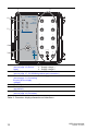
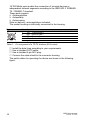
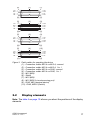
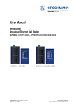
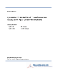
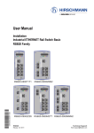
User Manual Installation OS20-Unmanaged x y P1 P2 1 6 2 7 3 8 4 9 OCTOPUS OS20 1 6 2 7 3 8 4 9 5 10 Unmanaged ETHERNET Switch Produktcode Power Power 5 3 2 4 1 Pin 1 2 3 4 5 TP - Ports 1 2 4 3 5 Function P1+ N.C. PP2+ N.C. 10 OS20–001000T5T5TAFUHB OS20-Unmanaged Release 03 12/10 Technical Support [email protected] The naming of copyrighted trademarks in this manual, even when not specially indicated, should not be taken to mean that these names may be considered as free in the sense of the trademark and tradename protection law and hence that they may be freely used by anyone. © 2010 Hirschmann Automation and Control GmbH Manuals and software are protected by copyright. All rights reserved. The copying, reproduction, translation, conversion into any electronic medium or machine scannable form is not permitted, either in whole or in part. An exception is the preparation of a backup copy of the software for your own use. For devices with embedded software, the end-user license agreement on the enclosed CD applies. The performance features described here are binding only if they have been expressly agreed when the contract was made. This document was produced by Hirschmann Automation and Control GmbH according to the best of the company's knowledge. Hirschmann reserves the right to change the contents of this document without prior notice. Hirschmann can give no guarantee in respect of the correctness or accuracy of the information in this document. Hirschmann can accept no responsibility for damages, resulting from the use of the network components or the associated operating software. In addition, we refer to the conditions of use specified in the license contract. You can get the latest version of this manual on the Internet at the Hirschmann product site (www.beldensolutions.com). Printed in Germany Hirschmann Automation and Control GmbH Stuttgarter Str. 45-51 72654 Neckartenzlingen Germany Tel.: +49 1805 141538 OS20-Unmanaged 039 771-001-03-1210 15.12.10 Contents Safety instructions 4 About this Manual 9 Legend 9 1 Device description 10 2 Assembly and start-up 13 2.1 Installing the device 2.1.1 Unpacking and checking 2.1.2 Connecting the plug for the supply voltage 2.1.3 Installing the device and grounding 2.1.4 Connecting the supply voltage, starting up 2.1.5 Connecting the data lines 13 13 13 14 15 15 2.2 Display elements 17 3 Technical data 19 A Further Support 23 OS20-Unmanaged Release 03 12/10 3 Safety instructions This documentation contains instructions which must be observed to ensure your own personal safety and to avoid damage to devices and machinery. Notes on safety This manual contains instructions to be observed for ensuring your personal safety and for preventing damage. The warnings appear next to a warning triangle with a different heading depending on the degree of danger posed: Danger! Means that death, serious physical injury or significant damage to property will occur if the corresponding safety measures are not carried out. Warning! Means that death, serious physical injury or significant damage to property could occur if the corresponding safety measures are not carried out. Caution! Means that minor physical injury or damage to property can occur if the required safety measures are not carried out. Note: Contains important information on the product, on how to manage the product, or on the respective section of the documentation to which your special attention is being drawn. Certified usage The device may only be employed for the purposes described in the catalog and technical description, and only in conjunction with external devices and components recommended or approved by the manufacturer. The product can only be operated correctly and safely if it is transported, stored, installed and assembled properly and correctly. Furthermore, it must be operated and serviced carefully. Certifications product code (see table 2 and table 3) F Operational environment In the inside of buildings In the inside of trains In the inside of ships In the inside of vehicles Table 1: Operational environment 4 OS20-Unmanaged Release 03 12/10 Warning! Do not use the device in safety-related applications - in particular where life and limb may be in danger. Supply voltage The supply voltage is electrically isolated from the housing. Use undamaged parts. Relevant for North America: For use in Class 2 circuits. Only use copper wire/conductors of class 1, 75 °C (167 °F). Ensure that the externally power unit connected upstream fulfills one of following conditions: X NEC Class 2 X Limited Power Source based on EN60950-1 Shielding ground Note: The shielding ground of the connectable twisted pair lines is connected to the housing as a conductor. Beware of possible short circuits when connecting a cable section with conductive shielding braiding. Housing Only technicians authorized by the manufacturer are permitted to open the housing. The device is grounded via the separate ground screw. Make sure that the electrical installation meets local or nationally applicable safety regulations. Warning! HOT SURFACE RISK OF BURNING! Warning! If the surrounding air temperature exceeds 55 °C, install the device exclusively in “restricted access locations” according to EN 60950-1 Environment The device may only be operated at the specified surrounding air temperature (temperature of the surrounding air at a distance of up to 5 cm (1.97 in) from the device) and relative air humidity specified in the technical data. OS20-Unmanaged Release 03 12/10 5 Install the device in a location where the climatic threshold values specified in the technical data are adhered to. Make sure the environment does not heat the device. It can be mounted on temperature-isolating material. Use the device only in an environment within the pollution degree specified in the technical data. Qualification requirements for personnel Qualified personnel as understood in this manual and the warning signs, are persons who are familiar with the setup, assembly, startup, and operation of this product and are appropriately qualified for their job. This includes, for example, those persons who have been: X trained or directed or authorized to switch on and off, to ground and to label power circuits and devices or systems in accordance with current safety engineering standards; X trained or directed in the care and use of appropriate safety equipment in accordance with the current standards of safety engineering; X trained in providing first aid. General safety instructions Please note that products recommended as accessories may have characteristics that do not fully correspond to those of the corresponding product. This may limit their possible usage in the overall system. Electricity is used to operate this equipment. Comply with every detail of the safety requirements specified in the operating instructions regarding the voltages to apply (see page 5). Non-observance of these safety instructions can therefore cause material damage and/or serious injuries. Only appropriately qualified personnel should work on this device or in its vicinity. These personnel must be thoroughly familiar with all the warnings and maintenance procedures in accordance with this operating manual. The proper and safe operation of this device depends on proper handling during transport, proper storage and assembly, and conscientious operation and maintenance procedures. Never start operation with damaged components. Only use the devices in accordance with this manual. In particular, observe all warnings and safety-related information. Any work that may be required on the electrical installation may only be carried out by personnel trained for this purpose. 6 OS20-Unmanaged Release 03 12/10 National and international safety regulations Make sure that the electrical installation meets local or nationally applicable safety regulations. CE marking The devices comply with the regulations contained in the following European directive(s): 2004/108/EG Directive of the European Parliament and the council for standardizing the regulations of member states with regard to electromagnetic compatibility. 72/245/EWG, 2009/19/EG Guideline for standardizing the regulations of member states relating to radio interference from motor vehicles. Certified devices are marked with an e1 type approval indicator. In accordance with the above-named EU directive(s), the EU conformity declaration will be at the disposal of the relevant authorities at the following address: Hirschmann Automation and Control GmbH Stuttgarter Str. 45-51 72654 Neckartenzlingen Tel.: +49 1805 141538 The product can be used in the industrial sector. X Interference immunity: EN 61000-6-2:2005 X Emitted interference: EN 55022:2006 + A1:2007 Class A Warning! This is a class A device. This device can cause interference in living areas, and in this case the operator may be required to take appropriate measures. Warning! The assembly guidelines provided in these instructions must be strictly adhered to in order to observe the EMC threshold values. FCC note: This device complies with part 15 of FCC rules. Operation is subject to the following two conditions : (1) This device may not cause harmful interference; (2) this device must accept any interference received, including interference that may cause undesired operation. OS20-Unmanaged Release 03 12/10 7 Appropriate testing has established that this device fulfills the requirements of a class A digital device in line with part 15 of the FCC regulations. These requirements are designed to provide sufficient protection against interference when the device is being used in a business environment. The device creates and uses high frequencies and can radiate same, and if it is not installed and used in accordance with this operating manual, it can cause radio transmission interference. The use of this device in a living area can also cause interference, and in this case the user is obliged to cover the costs of removing the interference. Recycling note After usage, this product must be disposed of properly as electronic waste, in accordance with the current disposal regulations of your county, state and country. 8 OS20-Unmanaged Release 03 12/10 About this Manual The “Installation” user manual contains a device description, safety instructions, a description of the display, and the other information that you need to install the device. Legend The symbols used in this manual have the following meanings: X Listing Work step Subheading OS20-Unmanaged Release 03 12/10 9 1 Device description The OS20-Unmanaged devices are designed for the special requirements of industrial automation. They meet the relevant industry standards, provide very high operational reliability, even under extreme conditions, and also long-term reliability and flexibility. The devices allow you to set up switched industrial ETHERNET networks that conform to the IEEE 802.3 and 802.3u standards using copper wires in a line structure. The devices work without a fan. The 10 twisted pair ports are M12 sockets. The twisted pair ports support: X Autocrossing X Autonegotiation X Autopolarity Mount the device on a level surface with four M5 screws. The Hirschmann network components help you to establish continuous communication across all levels of the company. Connect your devices to: X devices of the Open Rail family X devices of the MICE family X backbone devices of the MACH family X the BAT wireless transmission system X the EAGLE security system X products for the LION control room / MACH 100 family The table 2 informs you about the identification characteristics of your device. Product code OS20–001000T5T5TAFUHB Order number 942 025-001 Table 2: Device types: product code, order number The product designation of your device is made from combining the product characteristics in accordance with the following table. The corresponding short designation is in column 3. 10 OS20-Unmanaged Release 03 12/10 Item Characteristic 1,2,3,4 5 6,7 8,9 Number: Special ports Number: 100 Mbit/s ports Characteristic Description value OS20 Octopus device – 00 0× 10 10 × 00 0× 12,13 Number: 1000 Mbit/s ports Uplink ports T5 1× 14,15 Uplink ports T5 1× 16 Temperature T range Operating voltage A (see on page 13 „Connecting the plug for the supply voltage“) 10,11 17 18 Certifications F 19 20 21 Software variant Configuration Device model U H B Extended X without 1000 Mbit/s ports X without PoE ports PoE+ ports 100 Mbit/s ports (see on page 15 „10/100 Mbit/s twisted pair connection“) 1000 Mbit/s ports 100 Mbit/s ports (see on page 15 „10/100 Mbit/s twisted pair connection“) 100 Mbit/s ports (see on page 15 „10/100 Mbit/s twisted pair connection“) -40 °C to +70 °C Rated voltage range DC 24/36/48 V DC Note: For the railway standard EN50155 use 24 V DC and 36 V DC exclusively. Max. voltage range DC min. 9.6 to max. 60 V DC (Not for EN/IEC/UL 60950) Connection M12 type X Railway (along track) X Railway (train) X German Lloyd X E1 Unmanaged Hirschmann IP 54 Table 3: Combination options OS20-Unmanaged Release 03 12/10 11 1 2 x y 6 5 4 P1 P2 1 6 2 7 3 8 4 9 OCTOPUS OS20 1 6 2 7 3 8 4 9 5 10 Unmanaged ETHERNET Switch Produktcode Power Power 5 3 1 2 3 4 5 6 3 2 4 1 Pin 1 2 3 4 5 Function P1+ N.C. PP2+ N.C. TP - Ports 1 2 4 3 5 10 LED display elements Device Status (see on page 18 „Device X Supply voltage 1 X Supply voltage 2 state“) 100 Mbit/s ports (see on page 15 „10/100 Mbit/s twisted pair connection“) Connection Power supply (see on page 13 „Connecting the plug for the supply voltage“) Grounding screw M3 Product code (see table 3) LED display elements port state (see on page 18 „Port state“) Table 4: Overview: display elements and interfaces 12 OS20-Unmanaged Release 03 12/10 2 Assembly and start-up The devices have been developed for practical application in a harsh industrial environment. The installation process is correspondingly simple. On delivery, the device is ready for operation. The following procedure has been proven to be successful for the assembly of the device: X X X X X Unpacking and checking Connecting the plug for the supply voltage Installing the device and grounding Connecting the supply voltage, starting up Connecting the data lines 2.1 Installing the device 2.1.1 Unpacking and checking Check that the contents of the package are complete (see page 20 „Scope of delivery“) Check the individual parts for transport damage. 2.1.2 Connecting the plug for the supply voltage A 5-pin M12 connector (A coding, supplied) is used to connect the power supply. For the supply voltage, the following applies: X Operating voltage X Rated voltage range DC 24/36/48 V DC X Max. voltage range DC min. 9.6 to max. 60 V DC Note: For the railway standard EN50155 use 24 V DC and 36 V DC exclusively. X The input voltage is electrically isolated from the housing. X You can supply the supply voltage redundantly, with no load distribution. OS20-Unmanaged Release 03 12/10 13 Note: Ensure that the externally power unit connected upstream fulfills one of following conditions: X NEC Class 2 X Limited Power Source based on EN60950-1 Figure Table 5: 2.1.3 Pin 1 2 3 4 5 Function Plus terminal of the supply voltage Not connected Minus terminal of the supply voltage Plus terminal of the supply voltage Not connected Power supply Supply voltage 1 — Supply voltage 1 and 2 Supply voltage 2 — Pin assignment of the 5-pin M12 connector for connecting the supply voltage Installing the device and grounding Installing the device Warning! If the surrounding air temperature exceeds 55 °C, install the device exclusively in “restricted access locations” according to EN 60950-1 Note: To protect the exposed contacts of the components still to be installed from dirt, connect the individual system components in a dry and clean working area. Seal unused ports with the protection caps supplied. Note: Connectors are not electrical isolating devices. Therefore, first plug the connector into the power supply plug and then switch on the power supply. Install the device in a location where the climatic threshold values specified in the technical data are adhered to. Make sure the environment does not heat the device. It can be mounted on temperature-isolating material. Prepare the drill holes at the installation point. Mount the device on a level surface with four M5 screws. 14 OS20-Unmanaged Release 03 12/10 120 mm 4.73 inch 188,5 mm 7.43 inch 183,8 mm 7.24 inch 52,8 mm 2.08 inch 171,8 mm 6.77 inch Figure 1: Dimensions Grounding the device The device is grounded via the separate grounding screw (M3). Use toothed washers to ensure good electrical conductivity at the connection. Note: The shielding ground of the connectable twisted pair lines is connected to the housing as a conductor. 2.1.4 Connecting the supply voltage, starting up Mount the plug for the supply voltage on the front of the device. When you connect the supply voltage, you start up the device. 2.1.5 Connecting the data lines You can connect terminal devices and other segments at the ports of the device via twisted pair cables. 10/100 Mbit/s twisted pair connection These connections are M12 sockets. OS20-Unmanaged Release 03 12/10 15 10/100 Mbit/s ports enable the connection of terminal devices or independent network segments according to the IEEE 802.3 100BASETX / 10BASE-T standard. These ports support: X Autonegotiation X Autopolarity X Autocrossing State on delivery: autonegotiation activated. The socket housing is electrically connected to the housing. Figure Pin Function 1 TD+ Transmit Data + 2 RD+ Receive Data + 3 TD- Transmit Data 4 RD- Receive Data Housing: shield Table 6: Pin assignment of a TP/TX interface (M12 socket) Install the data lines according to your requirements. Use a shielded CAT5 cable. Use a shielded 4-pin M12 plug. Connect the cable shield to the connector housing. The patch cables for operating the device are shown in the following figure: 16 OS20-Unmanaged Release 03 12/10 (5) TX+ RX+ TXRX- (1) 1 2 3 4 1 2 3 4 (5) (2) RX+ TX+ RXTX- (6) (5) (3) 1 2 3 4 (9) 1 2 3 6 (6) TX+ TXRX+ RX- (6) (5) TX+ RX+ TXRX- (8) 1 2 3 4 1 2 3 4 (6) TX+ RX+ TXRX- TX+ RX+ TXRX- (6) (6) TX+ RX+ TXRX- (7) (4) 1 2 3 4 (10) 1 2 3 6 (6) RX+ RXTX+ TX- (6) Figure 2: Patch cables for operating the device (1) - Connection cables M12-4 on M12-4, crossed (2) - Connection cables M12-4 on M12-4, 1 to 1 (3) - Connection cables M12-4 on RJ45, crossed (4) - Connection cables M12-4 on RJ45, 1 to 1 (5) - M12 (MDI) (6) - Shield (7) - M12 (MDI) (8) - M12 (MDI-X via autocrossing port) (9) - RJ45, MDI (terminal device) (10) - RJ45, MDI-X (Switch) 2.2 Display elements Note: The table 4 on page 12 informs you about the positions of the display elements. OS20-Unmanaged Release 03 12/10 17 Device state These LEDs provide information about conditions which affect the operation of the whole device. LED P1 Display Supply voltage 1 Color Green P2 Supply voltage 2 Green Activity Lights up None Lights up None Meaning The supply voltage is on. The supply voltage is too low. The supply voltage is on. The supply voltage is too low. Port state The green and yellow LEDs at the individual port display port-related information. LED LS/DA Display Link status Color Green Yellow 18 Activity None Lights up Flashing Meaning No valid connection Valid connection Data traffic OS20-Unmanaged Release 03 12/10 3 Technical data General technical data Dimensions W×H×D Weight Power supply 184 mm × 189 mm × 70 mm 1300 g Redundant power supply Note: Ensure that the externally power unit connected upstream fulfills one of following conditions: X NEC Class 2 X Limited Power Source based on EN60950-1 Operating voltage Rated voltage range DC 24/36/48 V DC Note: For the railway standard EN50155 use 24 V DC and 36 V DC exclusively. Max. voltage range DC min. 9.6 to max. 60 V DC (Not for EN/IEC/UL 60950) Overload current Non-replaceable fuse protection at input Insulation voltage between operating voltage connections and housing Climatic conditions Surrounding air temperature during operation Humidity Air pressure Climatic conditions Surrounding air temperature during storage Humidity Air pressure Protection class Mounting Flat surface mounting Screw type Pollution degree 707 V DC -40 °C to +70 °C 10% to 95% (non-condensing) minimum 795 hPa (+2000 m) maximum 1060 hPa (-400 m) -40 °C to +85 °C 10% to 95% (non-condensing) minimum 700 hPa (+3000 m) maximum 1060 hPa (-400 m) IP 54 M5 2 EMC and immunity EMV interference immunity IEC/EN 61000-4-2 Electrostatic discharge Contact discharge Air discharge IEC/EN 61000-4-3 Electromagnetic field 80 - 2,700 MHz OS20-Unmanaged Release 03 12/10 6 kV 8 kV 20 V/m 19 EMV interference immunity IEC/EN 61000-4-4 Fast transients (burst) Power line Data line IEC/EN 61000-4-5 Voltage surges Power line Power line Data line IEC/EN 61000-4-6 Line-conducted interference voltages 150 kHz - 80 MHz EN 61000-4-9 Impulse-shaped magnetic fields 2 kV 4 kV 1 kV line / line 2 kV line / earth 1kV 10 V 300 A/m EMC emitted interference EN 55022 Class A FCC 47 CFR Part 15 Class A German Lloyd Classification + Construction Guidelines VI-7-3 Part 1 Ed.2001 Stability Vibration IEC 60068-2-6 Test FC test level according to IEC 61131-2 Germanischer Lloyd Guidelines for the Performance of Type Tests Part 1 IEC 870-2-2 table 3 normal installation according to EN 61850-3 EN 61373, Category 1, Class A (broadband noise), installation in acc. with EN 50155 Shock IEC 60068-2-27 Test Ea test level according to IEC 61131-2 IEC 870-2-2 table 3 normal installation according to EN 61850-3 EN 61373, Category 1, Class A (broadband noise), installation in acc. with EN 50155 Yes Yes Yes Yes Yes Yes Yes Yes Yes Yes Network range TP port Length of a twisted pair segment Table 7: typ. 100 m (cat5e cable with 100BASE-TX) TP port 10BASE-T / 100BASE-TX Power consumption/power output Name OS20–001000T5T5TAFUHB Maximum power consumption Power output 5.8 W 19.8 Btu (IT)/h Scope of delivery The cable socket ELWIKA 5012 PG7 (933 175-100) included in the delivery supports a temperature range from -25 °C to +70 °C. It can thus restrict the possible range of usage for the overall system. 20 OS20-Unmanaged Release 03 12/10 Device OS20–001000T5T5TAFUHB Scope of delivery Octopus device Cable socket ELWIKA 5012 PG7 for supply voltage Protective caps for sealing unused ports Installation user manual Order numbers/product description You can obtain the product code for the devices (order number) from the above table (see table 2) . Accessories Note: Some products recommended as accessories do not support the entire temperature range specified for the device. They can thus restrict the possible range of usage for the overall system. Note: Unsealed accessory parts are not suitable for use within an IP54 area. The following accessory parts are unsealed: X RJ45 adapters Name Pocket Guide Cable socket ELWIKA 5012 PG7 (5-pin M12 socket for supply voltage Field-attachable 5-pin M12 socket, A-coded with two cable outputs M12 connector, D-coded Connection cable with M12 connector, D-coded Transition M12 D-coded to RJ45 Order number 280 710-851 933 175-100 RKC5/Duo 934 445-001 934 497-00x 934 498-001 Underlying norms and standards Name EN 50121-4:2006 Railway applications - EMC - emitted interference and interference immunity for signal and telecommunication systems EN 50155:2007 Railway applications - electronic systems in railway vehicles EN 55022:2006 + A1:2007 IT equipment – radio interference characteristics EN 61000-6-2:2005 Generic norm – immunity in industrial environments EN 61131-2:2007 Programmable logic controllers FCC 47 CFR Part 15:2009 Code of Federal Regulations Germanischer Lloyd Ship Applications - Classification and Construction Guidelines VI-7-3 Part 1 Ed.2003 RL 72/245/EWG, 2009/19/EG e1 type certification for use in vehicles Table 8: List of norms and standards OS20-Unmanaged Release 03 12/10 21 The device has a certification based on a specific standard only if the certification indicator appears on the housing. However, with the exception of Germanischer Lloyd, ship certifications are only included in the product information under www.beldensolutions.com. 22 OS20-Unmanaged Release 03 12/10 A Further Support Technical Questions and Training Courses In the event of technical queries, please contact your local Hirschmann distributor or Hirschmann office. You can find the addresses of our distributors on the Internet: www.beldensolutions.com. Our support line is also at your disposal: X Tel. +49 1805 14-1538 X Fax +49 7127 14-1551 Answers to Frequently Asked Questions can be found on the Hirschmann internet site (www.beldensolutions.com) at the end of the product sites in the FAQ category. The current training courses to technology and products can be found under http://www.hicomcenter.com. Hirschmann Competence Center In the long term, excellent products alone do not guarantee a successful customer relationship. Only comprehensive service makes a difference worldwide. In the current global competition scenario, the Hirschmann Competence Center is ahead of its competitors on three counts with its complete range of innovative services: X Consulting incorporates comprehensive technical advice, from system evaluation through network planning to project planing. X Training offers you an introduction to the basics, product briefing and user training with certification. X Support ranges from the first installation through the standby service to maintenance concepts. With the Hirschmann Competence Center, you have decided against making any compromises. Our client-customized package leaves you free to choose the service components you want to use. Internet: http://www.hicomcenter.com. OS20-Unmanaged Release 03 12/10 23