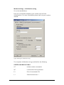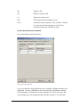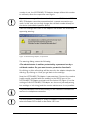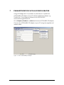
1
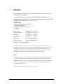
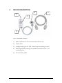
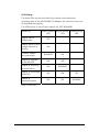
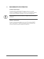
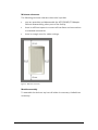
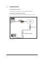
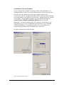
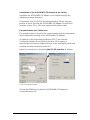
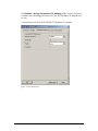
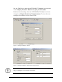
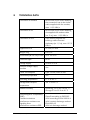
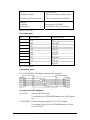
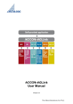
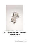
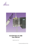
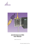
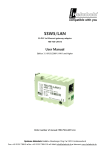
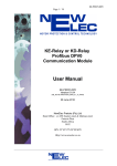
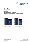
ACCON-MPI/TS-Adapter
User Manual
The Best Solutions for PLC
1
PREFACE
This manual is for project users, users and assemblers who utilize the
ACCON-MPI/TS-Adapter.
It shows the user the handling of the ACCON-MPI/TS-Adapter and
explains signaling functions. All necessary data for assembling should be
provided to the assembler. © 1995 - 2009
DELTALOGIC
Automatisierungstechnik GmbH
Stuttgarter Strasse 3
73525 Schwaebisch Gmuend
Germany
Phone sale:
Phone support:
+49-(0)7171-916-120
+49-(0)7171-916-112
Fax sale:
Fax support:
+49-(0)7171-916-220
+49-(0)7171-916-212
E-Mail sale:
E-Mail support:
[email protected]
[email protected]
Web site: www.deltalogic.de
All rights reserved. No part of this work is allowed to be copied, reproduced, conferred,
processed and stored into electronic media or translated into any other language without a
written permission of the author. S7-200®, S7-300®, S7-400®, HMI®, STEP® and
SIMATIC® are registered trademarks of Siemens AG, ACCON® and DELTALOGIC® are
registered trademarks of DELTALOGIC Automatisierungstechnik GmbH.
Note:
We have checked the content of this manual for conformity with the hardware and software
described. Nevertheless, because deviations cannot be ruled out, we cannot accept any
liability for complete conformity. The data in this manual have been checked regularly and
any necessary corrections will be included in subsequent editions. We always welcome
suggestions for improvement.
Last update 2008-03-18. All technical changes reserved.
ACCON-MPI/TS-Adapter
1
INHALTSVERZEICHNIS
1
PREFACE................................................................... 1
2
TECHNICAL DESCRIPTION...................................... 3
3
SCOPE OF DELIVERY ............................................... 5
4
DEVICE DESCRIPTION ............................................. 6
5
REQUIREMENTS FOR OPERATING ......................... 8
6
COMMISSIONING ..................................................10
7
PARAMETRIZATION WITH ACCONFIGURATOR ...17
8
TECHNICAL DATA ..................................................19
ACCON-MPI/TS-Adapter
2
2
TECHNICAL DESCRIPTION
The ACCON-MPI/TS-Adapter enables the connection of a PC to the MPI
interface of a S7 PLC via modem for the purpose of remote
maintenance. The ACCON-MPI/TS-Adapter uses the same communication protocol as the TS Adapter. So the ACCON-MPI/TS-Adapter can
be used with any software which supports the TS Adapter. The ACCONMPI/TS-Adapter can be used without the modem, too. In this case the
device behaves like an ordinary ACCON-MPI-Adapter respectively PC
Adapter. A bushing for the connection of a further node e.g. a control
panel console is located at the bus plug of the ACCON-MPI/TS-Adapter.
To operate the ACCON-MPI/TS-Adapter via a modem connection with
STEP 7 you need the TeleService option package from Siemens. When
using the ACCON-MPI/TS-Adapter in direct mode this option package is
not necessary.
Figure 1: Build-up
The functions »PG_DIAL« and »AS_DIAL« are not implemented.
ACCON-MPI/TS-Adapter
3
The ACCON-MPI/TS-Adapter cannot be used with S7-200 PLCs!
FM35x-modules cannot be parametrized with the ACCON-MPI/TSAdapter!
Features:
•
Can be used with Hayes compatible modems
•
Password protection
•
Call-back function
•
Can be directly used as programming adapter
•
Serial transmission rate of up to 115,2 KBit/s
•
MPI speed up to 187,5 KBit/s
•
Voltage feed from the CPU
•
External 24-V feed possible
•
Bus plug with PG bushing
ACCON-MPI/TS-Adapter
4
3
SCOPE OF DELIVERY
•
ACCON-MPI/TS-Adapter
•
Null modem cable (ca. 2 m)
•
User manual
Suitable accessories can be found on www.deltalogic.de.
ACCON-MPI/TS-Adapter
5
4
DEVICE DESCRIPTION
4
5
1
2
3
Figure 2: ACCON-MPI/TS-Adapter
1)
RS232 interface for the communication with the PC
2)
Status LEDs
3)
Voltage bushing for 24 VDC. Please keep the polarity in mind.
4)
Bus plug with PG bushing, connectable terminator and a 1,2 m
connection line.
5)
PC connection cable
ACCON-MPI/TS-Adapter
6
LED Display
The three LEDs on the front side of the device inform about the
operating state of the ACCON-MPI/TS-Adapter. So sources of error can
be detected very quickly.
The LEDs can be in one of three states: ON, OFF, BLINKING
Status LED
Power/Update Active/Param. Connect/Data
LED
LED
LED
Adapter has no
voltage feed.
OFF
Adapter has a 24 VDC
voltage feed and is
working
ON
Firmware update
being executed
BLINKING
ON
Adapter is logged in
on the MPI bus
ON
ON
Adapter is receiving
parametrization
ON
BLINKING
Adapter is connected
to the PLC
ON
ON
ON
Adapter is
transmitting data
ON
ON
BLINKING
Tabelle 1: Status LEDs
ACCON-MPI/TS-Adapter
7
5
REQUIREMENTS FOR OPERATING
Hardware requirements
If possible plug the ACCON-MPI/TS-Adapter directly on the MPI
interface of a SIMATIC S7-300 or S7-400 PLC. If not possible so please
connect the ACCON-MPI/TS-Adapter to an external voltage feed.
Please remember that the ACCON-MPI/TS-Adapter cannot be used with
PROFIBUS!
Software requirements
To use it as programming adapter you need a PC including SIMATIC
STEP 7 from version 5.1. When accessing a modem connection you
need the TeleService option package from Siemens.
ACCON-MPI/TS-Adapter
8
Minimum clearance
The following minimum clearance has to be kept that
•
you can assemble and disassemble the ACCON-MPI/TS-Adapter
without disassembling other parts of the facility.
•
there is sufficient space to connect all interfaces and connections
to standard accessories.
•
there is enough room for cable routings.
Figure 3: Minimum clearance
Module assembly
To assemble the device a top hat rail holder is necessary. Available as
accessory.
ACCON-MPI/TS-Adapter
9
6
COMMISSIONING
Connection to the modem
Put the RS232 connection cable on the modem's RS232 port.
Connection to the automation system
Connect the 9-pin SUB-D plug to the MPI interface of your S7 PLC.
Figure 4: Build-up
ACCON-MPI/TS-Adapter
10
Installation of the local modem
If you already have installed an analog modem under Windows, it is
mostly possible to use it for remote maintenance. In this case you can
skip the next step and use the already installed modem. After
connecting to the PC, plug&play modems will be detected automatically
and integrated into the system. But the driver, supplied with the modem,
is necessary. No plug&play modems can be installed manually via
Control Panel > Phone and Modem Options then in the tab
»Modems«. The driver supplied with the modem is needed here, too.
Alternatively, you can use a Windows standard driver (e.g. Standard
28800 bps Modem). The installed modem can be selected in the
programming software when establishing a connection.
Example: Adjusting the local modem
Figure 5: Adjusting local modem
ACCON-MPI/TS-Adapter
11
Installation of the ACCON-MPI/TS-Adapter at the facility
Assemble the ACCON-MPI/TS-Adapter in the cabinet keeping the
indicated minimum clearance.
If necessary, feed 24 VDC via the voltage bushing. Please keep the
polarity in mind. Connect the ACCON-MPI/TS-Adapter to the RS232
interface of your PC or PG via the supplied null modem cable.
Parametrization with TeleService
The software which is used for the communication with the automation
device adjusts the settings of the ACCON-MPI/TS-Adapter.
In addition to the programming software STEP 7 you need the
TeleService software from Siemens (Version 3.0 or higher) to
administrate connections (telephone book of the selectable plants) and
establish the dial connection to the PLC.
Adjust the connection in the dialog Set PG/PC Interface as follows:
Figure 6: Set PG/PC Interface
Choose the COM-Port to which the ACCON-MPI/TS-Adapter is
connected to your PC:
ACCON-MPI/TS-Adapter
12
Via Options > Assign Parameters TS Adapter I/II… in the TeleService
software the following preferences for the ACCON-MPI/TS-Adapter can
be set.
Transmission rate from ACCON-MPI/TS-Adapter to modem:
Figure 7: Serial Parameters
ACCON-MPI/TS-Adapter
13
Modem settings / Initialization string
Go to the tab »Modem«.
Enter the commands needed by your modem into the field
»Initialization«. For more information please look into your modem
manual.
Figure 8:Setting the initialization string
The complete initialization string could be like the following:
AT&FE1L1M1Q0V1&C1S0=1
AT
Initiate modem commands
&F
Load modem factory defaults
E1
Echo of commands ON
L1
Sound volume level 1
ACCON-MPI/TS-Adapter
14
M1
Speaker ON
Q0
Modem response ON
V1
Response in plain text
&C1
DCD signal shows available carrier
S0=1
Automatic call acceptance. The number 1 stands
for rings until call acceptance e.g. S0=3 the
modem accepts the call after 3 rings.
Access protection and call-back
Go to the tab »Access Protection«.
Figure 9: Access Protection
Here you can store three different users including call-back number and
password. The user »ADMIN« is the only one who is allowed to change
all the adapter's settings and all user settings. The other two users can
only change their own password and call-back numbers. If a call-back
ACCON-MPI/TS-Adapter
15
number is set, the ACCON-MPI/TS-Adapter always utilizes this number
to call back, when the respective user logs in.
If you enter a wrong call-back number for the user »ADMIN« the ACCONMPI/TS-Adapter cannot be parametrized via a remote connection any
more. In this case you can only change the call-back number directly at
the device (microswitch position »Ext.«)!
Save the settings with »OK« on the adapter and answer the eventually
appearing warning:
Figure 10: Parametrizing adapter, set protection
The warning dialog means the following:
»The administrator is neither protected by a password nor by a
call-back number. Do you want to set a protection function?«
By clicking on »No« all settings will be stored in the adapter despite the
warning. By clicking on »Yes« you get back to the settings.
Now the ACCON-MPI/TS-Adapter is parametrized. Connect the modem
(cable usually supplied with the modem) to the RS232 port of the
ACCON-MPI/TS-Adapter and wait until the Active LED lights. If not the
settings of the ACCON-MPI/TS-Adapter are incorrect (normally wrong
bus settings or init string) and the remote maintenance is not possible.
The parametrization can be done locally via the TeleService software as
well as via a telephone connection.
The ACCON-MPI/TS-Adapter is ready to establish a remote connection
when the Power LED as well as the Active LED is on.
ACCON-MPI/TS-Adapter
16
7
PARAMETRIZATION WITH ACCONFIGURATOR
Using ACCONfigurator it is possible to parametrize or update the
ACCON-MPI/TS-Adapter at any PC without additional software e.g.
TeleService. The program is located on the DELTALOGIC
Automatisierungstechnik-CD.
Go to Adapter/Product >…select and choose ACCON-MPI/TS-Adapter.
Connect the ACCON-MPI/TS-Adapter to your PC using the supplied null
modem cable.
Figure 11: Select ACCON-MPI/TS-Adapter
ACCON-MPI/TS-Adapter
17
Set the COM-Port to which the ACCON-MPI/TS-Adapter is connected
under Adapter/Product > Select com port/serial number.
Read out actual settings from the ACCON-MPI/TS-Adapter and enter
changes via Adapter/Product > Read parameter. To store the new
settings in the device click on »Save/End«.
Figure 12: Settings TS Adapter, network
Figure 13: Settings TS Adapter, modem and access protection
When using ACCONfigurator it is not possible to parametrize the ACCONMPI/TS-Adapter via a remote connection.
ACCON-MPI/TS-Adapter
18
8
TECHNICAL DATA
Connection to modem
RS232 with 9-pin SUB-D bushing,
the connection has to be via the
cable supplied with the modem,
max. 115,2 KBit/s
Connection to PC
RS232 with 9-pin SUB-D bushing,
via supplied null modem cable
(ca. 2 m), max. 115,2 KBit/s
Connection to PLC
9-pin SUB-D plug with PG
bushing, cable mounted
stationary (ca. 1,2 m), max. 187,5
KBit/s
Supported PLCs
S7-300, S7-400
Weight in kg
Ca. 0,18
Dimensions (W x H x D) in mm
54 x 105 x 30
Protection type
IP 20
Voltage supply
24 VDC ± 25 %
External voltage supply
possible
Yes
Power consumption
Type. 30 mA, max. 45 mA
Galvanically separated
Yes
Operating temperature
0 °C to 60 °C
Storage and transport
temperature
-20 °C to 60 °C
Relative humidity
Operating 5 % to 85 % at 30 °C,
Storage 5 % to 93 % at 40 °C
Electromagnetic compatibility
(EMC)
Transient emissions
interference resistance on
signaling lines
interference resistance ESD
ACCON-MPI/TS-Adapter
Class B according to EN55022
±2kV according to EN61000-4-4
±6kV contact discharge method
EN61000-4-2
±8kV air discharge method
19
Grid-pound HF interferences
EN61000-4-2
10V/m according to EN61000-43
10V according to EN61000-4-6
Specials
Produced:
Maintenance:
according to ISO 9002
maintenance free (no battery)
HF-radiance fields
Table 2: Technical data
Pin assignment
Pin
Sub-D plug PC
Sub-D plug MPI
1
DCD
n.c.
2
RXD
M24 VDC
3
TXD
LTG_B
4
DTR
RTS AS
5
GND
M5 VDC
6
DSR
P5 VDC
7
RTS
P24 VDC
8
CTS
LTG_A
9
RI
RTS PG
Table 3: Pin assignment
Connection cable
PC to ACCON-MPI/TS-Adapter (supplied with adapter)
Accessories for S7-Adapters
13012-HS
Top hat rail holder short
To assemble the ACCON-MPI-Adapters on a DIN top hat
rail
13012-24VDC External voltage supply 24 VDC for S7-Adapter
For voltage supply of the ACCON-MPI-Adapter if there
are no 24 VDC.
ACCON-MPI/TS-Adapter
20