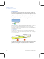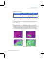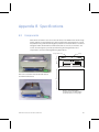
1
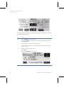
GE Healthcare Life Sciences WAVE Mixer™ 20/50 User Manual Contents Contents 1 Introduction 1.1 1.2 1.3 1.4 1.5 2 Installation 2.1 2.2 2.3 2.4 2.4.1 2.5 3 Important user information ......................................................................... 3 Regulatory information ................................................................................. 5 What is the WAVE Mixer? .............................................................................. 7 Features ................................................................................................................ 8 Instrument overview ....................................................................................... 9 Packing list .........................................................................................................13 Setting up the rocking unit .........................................................................14 Setting up the temperature control system ......................................17 Setting up the mixing bag ..........................................................................19 To lift bags containing liquid ......................................................................... 19 Ready to go .......................................................................................................20 Operating the WAVE Mixer 3.1 3.2 3.3 3.4 3.5 3.6 3.7 3.8 3.9 3.10 Components .....................................................................................................22 Preparing the WAVE Mixer for use .........................................................23 Setting operating conditions ...................................................................23 Operating the touchpanel controller ....................................................24 Operating the rocker ....................................................................................24 Operating the heater ....................................................................................25 Weight control .................................................................................................25 Trends ..................................................................................................................27 Alarms ..................................................................................................................28 Setup and options ..........................................................................................32 Appendix A Technical reference A.1 WAVE Mixer theory of operation .............................................................41 Appendix B Specifications B.1 Components .....................................................................................................45 Appendix C Troubleshooting C.1 C.2 C.3 C.4 C.5 Alarm messages .............................................................................................49 General problems ...........................................................................................50 Temperature controller ...............................................................................51 Speed controller ..............................................................................................51 Power failure .....................................................................................................52 Appendix D Communications and data acquisition WAVE Mixer 20/50 User Manual 28-9538-66 AC 1 Contents D.1 D.2 D.3 D.4 D.5 D.6 D.7 D.8 D.9 Overview ............................................................................................................ 53 Analog/alarm port ......................................................................................... 53 Alarm contact .................................................................................................. 54 Digital communication protocol ............................................................. 54 Changing address and baud rate .......................................................... 55 Communication wiring ................................................................................ 56 Connecting other WAVE instruments ................................................... 57 Connecting to Ethernet and plant networks ..................................... 58 Connecting to PCs and SCADA systems .............................................. 58 Appendix E Maintenance E.1 E.2 E.3 E.4 E.5 2 Routine maintenance .................................................................................. 59 Batteries ............................................................................................................. 59 Calibration ......................................................................................................... 60 Change of fuses .............................................................................................. 61 Spare parts ........................................................................................................ 62 WAVE Mixer 20/50 User Manual 28-9538-66 AC 1 Introduction 1.1 Important user information Read this before using WAVE Mixer 20/50 All users must read the WAVE Mixer 20/50 Operating Instructions before installing, using or maintaining the system. Do not operate WAVE Mixer 20/50 in any other way than described in the user documentation. If you do, you may be exposed to hazards that can lead to personal injury and you may cause damage to the equipment. Intended use The WAVE Mixer 20/50 is a device for mixing, warming, and reconstituting materials contained in sealed plastic bags. WAVE Mixer 20/50 shall not be used in any clinical procedures, or for diagnostic purposes. Safety notices This user documentation contains WARNINGS, CAUTIONS and NOTICES concerning the safe use of the product. See definitions below. WARNING WARNING indicates a hazardous situation which, if not avoided, could result in death or serious injury. It is important not to proceed until all stated conditions are met and clearly understood. WAVE Mixer 20/50 User Manual 28-9538-66 AC 3 1 Introduction 1.1 Important user information CAUTION! CAUTION indicates a hazardous situation which, if not avoided, could result in minor or moderate injury. It is important not to proceed until all stated conditions are met and clearly understood. NOTICE! NOTICE indicates instructions that must be followed to avoid damage to the product or other equipment. Notes and tips Note: A Note is used to indicate information that is important for trouble-free and optimal use of the product. Tip: A tip contains useful information that can improve or optimize your procedures. Typographical conventions Software texts and commands are identified by bold italic text. A colon is used to separate menu levels (e.g. File:Open refers to the Open option in the File menu). 4 WAVE Mixer 20/50 User Manual 28-9538-66 AC Introduction 1 Regulatory information 1.2 1.2 Regulatory information This section lists the directives and standards that are fulfilled by WAVE Mixer 20/ 50. Manufacturing information Requirement Content Name and address of manufacturer GE Healthcare Bio-Sciences AB, Björkgatan 30, SE 751 84 Uppsala Sweden Name and ID of notified body for European market (97/23/EC) INTERTEK SEMKO AB, NB 0413 CE Conformity Directive Title 2006/42/EC Machinery Directive (MD) 2006/95/EC Low Voltage Directive (LVD) 2004/108/EC ElectroMagnetic Compatibility (EMC) Directive International standards Standard Description Notes EN 61010-1 Safety requirements for electrical equipment for measurement, control and laboratory use EN standard is harmonized with EU directive 2006/95/EC Electrical equipment for measurement, control and laboratory use - EMC requirements EN standard is harmonized with EU directive 2004/108/EC IEC 61010-1 EN 61326-1 IEC 61326-1 (Emission according to CISPR 11, Group 1, class A) WAVE Mixer 20/50 User Manual 28-9538-66 AC 5 1 Introduction 1.2 Regulatory information Standard Description Notes EN ISO 12100 Safety of machinery. General principles for design. Risk assessment EN ISO standard is harmonized with EU directive 2006/42/EC and risk reduction. CE marking The CE marking and the corresponding Declaration of Conformity is valid for the instrument when it is: • used as a stand-alone unit, or • connected to other CE-marked instruments, or • connected to other products recommended or described in the user documentation, and • used in the same state as it was delivered from GE Healthcare, except for alterations described in the user documentation or explicitly authorized by GE Healthcare. Regulatory compliance of connected equipment Any equipment connected to WAVE Mixer 20/50 should meet the safety requirements of EN 61010-1/IEC61010-1 or relevant harmonized standards. Within the European Union, connected equipment must be CE-marked. 6 WAVE Mixer 20/50 User Manual 28-9538-66 AC Introduction 1 What is the WAVE Mixer? 1.3 1.3 What is the WAVE Mixer? The WAVE Mixer™ is a system for mixing, dispersing, and reconstituting materials contained in plastic bags. Unlike any other mixer, it does not require an invasive device within the bag, thus guaranteeing a completely sterile operation. The sealed bag is placed on the WAVE Mixer platform. The platform rocks the bag back and forth at an optimized rate. The rocking motion rapidly (within 10 to 15 seconds) mixes the contents of the bag. WAVE Mixer consists of two components: 1) the specially designed rocking unit, and 2) a fiberglass tray to hold the disposable plastic bag. The bag is partially filled (75% max for 20L, 70% max for 50L) with the liquid or powdered components to be mixed and then placed on the rocking unit. The rocking motion can be adjusted to provide the desired degree of mixing. Standard bioprocessing bags or specialized M*Bag™ from WAVE can be used. The M*Bag is optimized for the WAVE Mixer and has a large screw-cap port for easy addition of ingredients Fig 1-1. WAVE Mixer with 50 liter MIXKIT50EH (left) and with 20 liter MIXKIT20EH (right). The WAVE Mixer is ideal for mixing, warming, and thawing in completely sealed bags. WAVE Mixer 20/50 User Manual 28-9538-66 AC 7 1 Introduction 1.4 Features 1.4 Features Disposable mixing chamber The contact surface is a disposable plastic bag. This eliminates cleaning, sterilization, cross-contamination concerns, and other validation issues. Scalable The Wave Mixer 20/50EHT can handle bags with a liquid volume up to 15 liters using the MIXKIT20EH and up to 35 liters using the MIXKIT50EH. The holders are interchangeable on the same Wave Mixer 20/50EHT base. Built-in temperature control and heating enables thawing and warming operations within a completely sterile environment. Completely closed system The WAVE Mixer is ideal for high containment applications and GMP operations. It operates as a completely closed system with no seals. Utilizes standard bags WAVE Mixer is designed to utilize standard bags from various manufacturers. This enables the use of previously validated containers for mixing applications. No mechanical mixer The rocking motion induces a wave action that promotes mixing without shear. Maintenance costs are reduced due to the absence of any mechanical seals or impeller. Easy to operate The WAVE Mixer has no complex piping. Simply place the bag with the materials to be mixed into the WAVE Mixer bag holder and start the unit. Mixing to homogeneity typically takes less than one minute. Heating/thawing capability Temperature control is achieved by the built-in heater unit. The heater is powerful enough to thaw frozen materials in a few hours. 8 WAVE Mixer 20/50 User Manual 28-9538-66 AC Introduction 1 Instrument overview 1.5 1.5 Instrument overview Instrument parts and front panel 1 2 3 4 1 Bag surface temperature probe 2 Tray: stainless-steel lined fiber glass bag holder with internal heater and temperature sensor. 3 WAVE Mixer 20/50EH instrument 4 Touchpanel controller Instrument side panel 1 2 3 1 Touchpanel controller jack with Touchpanel cord connected 2 Temperature sensor jack with temperature sensor cord (yellow) connected 3 Touchpanel controller WAVE Mixer 20/50 User Manual 28-9538-66 AC 9 1 Introduction 1.5 Instrument overview Instrument rear panel (230 V model shown) 1 3 2 10 4 5 6 7 8 9 10 1 Instrument label 2 Dataport 1 and 2 jacks 3 Feed pump and Harvest pump jacks (not used) 4 Alarm analog out jack 5 Load cell jack 6 Filter heater jacks (not used) 7 Heater jack. Note, different for 230 V model (shown) and 120 V model (not shown) 8 Mains power switch 9 Fuses 10 Mains power inlet WAVE Mixer 20/50 User Manual 28-9538-66 AC 2 Installation This chapter provides information regarding installation of WAVE Mixer 20/50. WARNING! Protective ground. The WAVE Mixer 20/50 instrument must always be connected to a grounded power outlet. WARNING! The system must only be opened by a trained technician. It contains high voltage circuits that can give a lethal shock. WARNING! Please ensure that the instrument voltage ratings are set as per line voltage. WARNING! Always ensure that the unit is completely dry before plugging it in. Make sure to follow all environmental, health, and safety guidelines pertaining to the materials used. WARNING! Access to power switch. Do not block the rear of the instrument. The power switch must always be easy to access. WARNING! The HEATER outlet operates at line voltage. Do not operate the unit without the Heater Pad connected. WARNING! Remove any spillage on the floor immediately to minimize the risk for slipping accidents. WAVE Mixer 20/50 User Manual 28-9538-66 AC 11 2 Installation WARNING! Make sure no one enters the danger zone while the system is operating with the rocker in motion. WARNING! Do not move the WAVERMIXER instrument with a bag containing liquid. The combined weight of instrument and filled bag is too heavy. WARNING! Heavy object. Filled mixing bags have considerable weight and heavylifts must be done with care. Use 1 person per multiple of 15 kg weight, for example 3 persons for 30 to 45 kg. All lifting and moving must be performed in accordance with local regulations. CAUTION! Ensure that all tubing, hoses and cables are placed so that the risk or tripping accidents is minimized. CAUTION! Disconnect all tubing, hoses and cables before moving the WAVE Mixer unit. CAUTION! Only use chemicals that have been proven not to be harmful to the bag and the system. Pre-requisites 12 • The Wave Mixer 20/50EHT requires free space around it so the rocking motion is not obstructed. There should be enough space left for easy access to the whole equipment, both for normal operation and maintenance and service operations. At least 30.5 cm (12 inches) workspace around the unit. • The system should be installed on a stable laboratory bench. To ensure correct ventilation, the system requires a free space of 0.1 m behind and in front of it. Do not place soft material under the system. It might block the ventilation inlet. WAVE Mixer 20/50 User Manual 28-9538-66 AC Installation 2 Packing list 2.1 • The system can be operated at normal ambient temperatures. It should be located in a place of low temperature variations, away from heat sources, draughts and direct sunlight. • There are two models of Wave Mixer 20/50EHT. One model requires nominal 110 to 120 V~ 50/60 Hz electrical supply with safety grounding and the other model requires nominal220 to 240 V~, 50/60 Hz electrical supply with safety grounding. 2.1 Packing list Before you get started, please check to see that your WAVE Mixer package includes all the items and options you ordered. If any parts are missing, contact your WAVE Mixer dealer immediately. If all parts are present, then proceed on for installation instructions. WAVE Mixer 20/50 User Manual 28-9538-66 AC 13 2 Installation 2.2 Setting up the rocking unit 2.2 Setting up the rocking unit The WAVE Mixer rocking unit provides a reliable way of imparting a smooth wave motion to the bag contents. 1 Unpack the rocking unit. Locate the touchpanel controller and plug it into the side panel using the provided coiled cord. Slide the controller on the clip on the front panel. 2 Examine the rear of the unit and locate the HEATER inlet. Connect the MIXKIT cable (blue) at the rear of the instrument. Power inlet 14 WAVE Mixer 20/50 User Manual 28-9538-66 AC Installation 2 Setting up the rocking unit 2.2 WARNING! The Heater connector (blue cable) MUST be plugged in before plugging in the mains cable. The HEATER outlet operates at line voltage. Do not operate the unit without the Heater Pad connected. 3 Locate the power inlet at the rear of the unit. Plug the supplied electrical cord into the power inlet and connect the other end to a suitable power supply. WARNING! Make sure that there is enough free space around the Instrument for the rocking motion. Note: If the rocking motion is obstructed (by a hand or other object), the safety touch switches will stop the rocking motion and bring the rocker to the level position. Power must be cycled OFF and ON to reset the safety switch. The touchpanel will blink RED and display SAFETY BUMPER HIT indicating that the machine has stopped due to a fault. 4 Switch the main power switch located at the rear of the instrument on (I). 5 The panel should light up and the unit should start tilting slowly towards the rear. It will contact the rear safety switch (white touchbar) and then move towards the front until it hits the front safety switch. Next the rocker will move to the sampling position (front down 6°). If the AUTOSTART option is set to ON and the rocker was rocking when shut down it will resume rocking on startup. The initialization operation verifies the correct operation of the safety switches and also resets the angle measurement datum. During the initialization process the touchpanel blinks orange and displays INITIALIZING until initialization is complete. WARNING! There is a pinching hazard during this step. Avoid the Danger zones of the instrument. For information about Danger zone refer to the WAVE Mixer 20/50 Operating Instructions. WAVE Mixer 20/50 User Manual 28-9538-66 AC 15 2 Installation 2.2 Setting up the rocking unit 6 On successful initialization the touchpanel will display the MAIN MENU: Will be solid if ON UNIT address 7 Press ROCKER to access the rocker control menu. Press the ROCK button to start the rocking. The button will change to STOP. Press STOP to stop the rocker. 8 Change the speed setpoint on the speed controller by touching the setpoint box (left of SP legend). A numeric keypad will appear. Enter a new setpoint and press the key. Verify that the unit rocks and controls at the speed setpoint. Try changing the setpoint to other values (6 - 40 rpm). Observe correct operation. 9 The rock angle is displayed next to the ROCK/MAIN button. Press the angle value to bring up the angle change keypad. Change the rock angle by entering a new value (2 to 12 degrees). 10 If the unit does not operate, first check that you have power and that the touchpanel is lit. If unit still does not operate, refer to Appendix C for troubleshooting hints. 16 WAVE Mixer 20/50 User Manual 28-9538-66 AC Installation 2 Setting up the temperature control system 2.3 2.3 Setting up the temperature control system Temperature control is optional. To utilize temperature control, you must purchase a MIXKIT20EH or MIXKIT50EH. These trays have stainless steel interior and attached power/sensor cords. To use the heater, you must setup the unit as a Wave Mixer 20/50EHT (Electrically Heated). Contact GE Healthcare to change the unit setup. WARNING! Use only MIXKIT 500 W in Wave Mixer 20/50EHT. 1 Place the top plate onto the bioreactor rocker base and align the 4 mounting holes (shown as red circles below). Ensure that two holes located to the right in the figure below, is towards the front of the machine. Fasten using the provided 4 mounting screws and Allen key. WAVE Mixer 20/50 User Manual 28-9538-66 AC 17 2 Installation 2.3 Setting up the temperature control system 2 Place the MIXKIT20EH or MIXKIT50EH (shown below) tray on the rocker platform with the cords towards the rear. Plug the blue heater cable into the connector located on the rear of the rocker unit Bag surface temperature probe Stainless-steel lined fiber glass bag holder with internal heater and temperature sensor WARNING! The HEATER outlet operates at line voltage. Do not operate the unit without the Heater Pad connected. 3 Route the sensor cord (yellow) and plug it into the temperature sensor jack on the side panel. Screw the locking nut to firmly secure the plug. The HEATER has a thermal shutoff if the surface temperature exceeds 90°C. If this occurs, the heating will be shut off and a HEATER FAULT alarm will sound. 4 Use the touchpanel and switch to the HEATER screen. Verify that the BAG and PAN temperatures are close to ambient temperature. Maximum BAG temperature is 55°C and maximum PAN temperature is 75°C. Note: To verify the heater interlock, unplug the heater pad power cable. Unplugging should cause the HEATER FAULT alarm. 18 WAVE Mixer 20/50 User Manual 28-9538-66 AC Installation 2 Setting up the mixing bag 2.4 2.4 Setting up the mixing bag Do not fill the bag to more than to 75% of total volume for 20L M*Bags or 70% for 50L M*Bags. A larger fill volume will damp out the wave motion and drastically reduce the mixing efficiency. A bag containing liquid is heavy. Follow the instructions given in Section 2.4.1 for lifting. Place the bag into the MIXKIT and start the rocker. Typically use 25 to 30 rocks per minute to keep material in suspension. Use a higher rock rate of 30 to 40 rocks per minute for dissolution. Simply place a bag containing the material to be warmed or thawed in the bag holder according to such that it is on top of the Pt100 sensor. The set point of the heater can be adjusted (see Chapter 3) to provide any desired surface temperature. 2.4.1 To lift bags containing liquid Depending on the weight of the bag filled with liquid: • 0 to 15 kg: 1 person • 15 to 30 kg: 2 persons • 30 to 35 kg: 3 persons To lift a bag on the tray 1 Move the bag from the freezer to the WAVE Mixer using a trolley. 2 Place the trolley with the bag beside the WAVE Mixer. 3 Lift the bag with the number of persons recommended above. Note: A lifting device such as pallet lift can be used to facilitate the lifting. To lift a bag off the tray For easy removal of the bag from the WAVE Mixer it is recommended to lift the tray (white box on top of the WAVE Mixer) together with the bag. 1 Disconnect the WAVE Mixer from the mains current 2 Disconnect the blue cable from the WAVE Mixer Base (rear panel) 3 Disconnect the yellow temperature cable from the WAVE Mixer Base (side panel) WAVE Mixer 20/50 User Manual 28-9538-66 AC 19 2 Installation 2.5 Ready to go 4 Grip the corners of the tray and lift the tray and bag with the number of persons recommended above. 5 Place the tray with the bag adjacent to a trolley. 6 Lift the bag, with the number of persons recommended above, to a trolley and transport the bag to desired location. 7 Replace the tray to the instrument and reconnect the yellow and blue cables, see steps 2 and 3. 8 Connect the instrument to the mains outlet. 2.5 Ready to go Your WAVE Mixer rocking unit is now ready for operation. See the next section for instructions on how to use the WAVE Mixer. 20 WAVE Mixer 20/50 User Manual 28-9538-66 AC 3 Operating the WAVE Mixer Operating the WAVE Mixer is very easy. This section should have you up and running in less than 10 minutes. WARNING! Inspect all connections and tubing before start and replace any defective parts. WARNING! Electrical shock hazard after spillage. If there is a risk that large volumes of spilled liquid may penetrate the casing of WAVE Mixer 20/50 , immediately switch off the instrument, disconnect the power cord, and contact an authorized service engineer. WARNING! Burning hazard. In case of error some surfaces may become hot with temperatures above 75ªC, which is the normal maximum temperature. The heater has a thermal shut off when surface temperature exceeds 90ªC. WARNING! The WAVE Mixer should not be used for any application other than specified by the manufacturer. Only M*Bags or WAVE approved bags may be used on this equipment. Dispose of used bags according to local laws and regulations. CAUTION! Make sure that no body parts are caught between the base enclosure and the tray while rocking. CAUTION! Do not use the WAVE Mixer 20/50 in a dusty atmosphere or close to spraying water. WAVE Mixer 20/50 User Manual 28-9538-66 AC 21 3 Operating the WAVE Mixer 3.1 Components 3.1 Components The rocker unit The WAVE Mixer consists of two components: 1) a rocker unit that induces a wave motion in the mixing bag; and 2) the bag holder. The rocker unit is of very durable construction and is designed for continuous operation. The rocker unit is operated electrically. Connect the power cord located at the rear of the instrument to a suitable electrical power supply. The main power switch is located near the power inlet. All functions are controlled using the detachable touchpanel. Temperature is controlled by a heating plate located inside the MIXKIT20EH or 50EH. A Pt100 temperature sensor is attached on the inside of the holder. The probe plugs into a jack located on the rear of the unit. The bag to mixed, heated, or thawed is placed in the holder so that it is on top of the sensor, enabling a noninvasive temperature measurement. The bag holder The fiberglass holder is designed to hold M*Bags and standard geometry bags. The WAVE MIixer 20/50EHT comes with either a 20 liter holder (MIXKIT20EH) or larger 50 liter holder (MIXKIT50EH). Smaller bags can be accommodated by using foam inserts in the holder. Mixing can be done in any suitable bag. The bag material and design must be resistant to fatigue and cracking. Please contact for list of standard bags suitable for use on the WAVE Mixer. You can also get custom bags with any desired fittings, including screw cap ports for dry ingredients. 22 WAVE Mixer 20/50 User Manual 28-9538-66 AC Operating the WAVE Mixer 3 Preparing the WAVE Mixer for use 3.2 3.2 Preparing the WAVE Mixer for use Due to the disposable design, a WAVE Mixer can be prepared for use within a few minutes: 1 Place the WAVE Mixer holder on the rocker platform. 2 Fill the bag with the materials to be mixed, thawed, or warmed. Note: The bag must NOT be filled beyond 75% of its nominal maximal capacity, otherwise the wave action will be drastically reduced and the mixing efficiency will be very poor. 3.3 3 Place the bag into the holder. 4 Use the touchpanel ROCKER screen to set the rocker ON. Change the rocking speed to 30. For heating, set the desired setpoint on the touchpanel (HEATER screen) and press HEAT to activate temperature control. A HEATERFAULT alarm indicates that the heater plate is not connected, or has shutdown due to overheating. The PAN temperature sets the maximum skin temperature (default = 55°C). 5 To shut down the unit, turn the power off or use the touchscreen to shut down rocking and heating. Setting operating conditions The characteristics of the materials to be mixed will require some optimization of operating conditions. The following table provides some typical settings: Liquid vol/Total bag vol. Rocking rate (rpm) 5 L / 20 L 20 10 L / 20 L 30 15 L / 50 L 25 30 L / 50 L 25 to 35 The rocking rate should be set at the minimum rate that provides mixing without excessive foaming. In general, any rocking rate higher than 15 rocks per minute will be sufficient for particle suspension and bulk mixing. Typically, a rocking rate of 25 to 40 rocks per minute will satisfy most mixing requirements. The rock angle is set to an optimum value of 10°. The angle can be changed by the user. WAVE Mixer 20/50 User Manual 28-9538-66 AC 23 3 Operating the WAVE Mixer 3.4 Operating the touchpanel controller Rocking rate determines mixing but rocking too fast will cause foaming Note: It is critical that the rocking speed be sufficient to generate a visible surface wave. Some foam is normal, but reduce the rocking speed or angle if you see large "icebergs" of foam floating around, or if more than 50% of the surface is covered with foam. 3.4 Operating the touchpanel controller The detachable touchpanel controller is used to control all functions. It must be plugged into the WAVE Mixer base unit to operate. Pressing on the buttons and setpoint (black background) fields depicted on the touchpanel allows the user to start/stop and enter parameters. 3.5 Operating the rocker Press the ROCKER button from the MAIN MENU to access the rocker controls. Changing the rocking speed Press the setpoint display to bring up the speed setpoint entry keypad. Enter the new desired value in rpm (6 to 40). Changing the rock angle Press the setpoint display to bring up the angle entry keypad. Enter the new desired value in degrees. Rocker ON/OFF Press ROCK to start rocking. The button will change to STOP. Pressing STOP will stop rocking. Press BACK to return to the MAIN MENU. 24 WAVE Mixer 20/50 User Manual 28-9538-66 AC Operating the WAVE Mixer 3 Operating the heater 3.6 3.6 Operating the heater Press the HEATER button from the MAIN MENU to access the heater controls. BAR graph shows the current heater output Changing the setpoint Press the setpoint display to bring up the setpoint entry keypad. Enter the new desired value. It is not possible to set a temperature value above the maximum temperature values for pan and bag. Heater ON/OFF Press HEAT to turn temperature control on. The button will change to OFF. Pressing OFF will deactivate temperature control. Press BACK to return to the MAIN MENU. The HEATER screen shows the current BAG and PAN temperature. You can set the MAX pan temperature. • Maximum set temperature BAG: 55°C • Maximum set temperature PAN: 75°C 3.7 Weight control Weight control requires the instrument MIXER 20/50 to have LOAD CELL provision i.e. MIXER 20/50EHT-L. The weight is controlled from the WEIGHT screen. Settings for desired net weight are entered, and the feed and harvest pumps are controlled. WAVE Mixer 20/50 User Manual 28-9538-66 AC 25 3 Operating the WAVE Mixer 3.7 Weight control The following steps describe the procedure for setting the weight and controlling the feed and harvest pumps. Step 1 Action Select WEIGHT on the main screen. Result: The WEIGHT screen opens. The current net weight in kg is shown in the Kg net box. 2 Press the SP box to set the net weight set point. 3 Enter desired set point (0.2 to 25 kg) in the data entry keypad that opens. Press the key. 4 Optional: To set net weight to zero: Press TARE. Result: The TARE NOW? screen opens. 26 WAVE Mixer 20/50 User Manual 28-9538-66 AC Operating the WAVE Mixer 3 Trends 3.8 Step Action 5 Press TARE NOW to set the net weight to zero. This cannot be undone. or Press CANCEL to return to the WEIGHT screen. 6 Start the feed pump by pressing the ON button below FEED. Note: The FEED pump does not turn on if the net weight is higher than the high alarm limit. Result: The button changes to OFF and the indicator Feeding appears. The feed pump runs until the net weight is above the setpoint. Optional: To stop Feed control in advance press OFF to disable the FEED controller. 7 Start the harvest pump by pressing the ON button below HARV. Note: The harvest pump (HARV) does not turn on if the net weight is less than the low alarm limit. Result: The button changes to OFF and the indicator Harvesting appears. The harvest pump runs until the net weight is below the setpoint. Optional: To stop Harvest control in advance, press OFF to disable the HARV controller. 3.8 Trends Simple trends of the rocking speed and temperature (-EHT option only) are displayed for monitoring and troubleshooting. Press TREND from the ROCK or HEATER menu to access the trends. The trends show the last 10 minutes of data. Press BACK to return to the MAIN MENU. WAVE Mixer 20/50 User Manual 28-9538-66 AC 27 3 Operating the WAVE Mixer 3.9 Alarms 3.9 Alarms Alarms are handled using the ALARMS screen. Each alarm message has: • The date and time the alarm occurred or when it was cleared. • Alarm status (Alm = not cleared, OK = cleared). • The alarm code number, and a short description (see Alarm messages, in Appendix C). The alarm history for the last 1000 alarms is available from the touch screen. This history is retained even in case of a power failure or shutdown. However, if the touch screen is interchanged between the WAVE Bioreactor instruments, the alarm history is lost. A new alarm is indicated by: • A flashing button- A flashing ALARM button appears on the bottom of the displayed screen. • Change in background color- The screen background color changes to red. This indicates that the alarm has not been acknowledged. • Audible alarm- An audible alarm sounds if the ALM_BEEPER is set to ON. The default value is OFF and the audible alarm sound can be turned off via the SETUP screen. Each alarm is recorded on the ALARMS screen. Note: Ususally, the user must acknowledge any new alarm by pressing the ALARM button to view the alarm history screen. If the AUTOACK feature is set to ON in the SETUP:OPTIONS screen then all alarms are automatically acknowledged. No warnings are generated but the alarm is still logged. 28 WAVE Mixer 20/50 User Manual 28-9538-66 AC Operating the WAVE Mixer 3 Alarms 3.9 To acknowledge an alarm To acknowledge the alarm, follow the steps below. Step Action 1 Press the ALARM button displayed at the bottom of screen. Result: The alarm is acknowledged. The ALARMS screen is displayed and the screen color changes to green as shown in the picture below. The audible alarm sound stops. WAVE Mixer 20/50 User Manual 28-9538-66 AC 29 3 Operating the WAVE Mixer 3.9 Alarms Step 2 Action Press the BACK button on the ALARMS screen. Result: The main screen with a green background is displayed and the ALARM button disappears, as shown in picture below. Note: If the main screen continues to show the ALARM button with a green background, it means that the alarm condition still exists, as shown in the picture below. 30 WAVE Mixer 20/50 User Manual 28-9538-66 AC Operating the WAVE Mixer 3 Alarms 3.9 To handle an alarm All alarms have a specified code and are time-stamped to facilitate troubleshooting (see Alarm messages, in Appendix C). Follow the steps below to handle an alarm. Step Action 1 Press the ALARM button on the main screen. Result: The ALARMS screen opens. This action also acknowledges the alarm. 2 Press Up or Down buttons to scroll through the alarm history list. 3 If you need help with the alarms: • Press desired alarm to highlight it. • Press HELP to display the help screen. 4 Press the Active Alarms button, to get a list of currently active alarms. 5 Check the alarm and solve the alarm issue. Refer to Appendix C for Alarm messages and alarm codes. WAVE Mixer 20/50 User Manual 28-9538-66 AC 31 3 Operating the WAVE Mixer 3.10 Setup and options To view the alarm history and active alarm list To view the alarm history and active alarms list follow the steps below.: Step Action 1 Press the ALARM button in the main screen (if visible) or 2 Press MENU in the main screen and next ALARM in the MENU screen. 3.10 Setup and options Pressing the MENU button (MAIN screen) will bring up the MENU screen: SETUP button Pressing the SETUP button will bring up password entry screen that restricts access to the SETUP parameters. Click on the password entry box and use the pop-up keypad to enter the password - 2050 In addition to providing access to the SETUP parameters, the SETUP screen also provides useful system information: 32 Version The current software version is displayed on the left side. Date and Time The current date and time is shown. Unit Address This is the current MODBUS address of the unit. This is important when connecting the unit for data acquisition and supervisory control. Operating Hrs This is the total number of hours that the unit has been rocking. WAVE Mixer 20/50 User Manual 28-9538-66 AC Operating the WAVE Mixer 3 Setup and options 3.10 SETUP screen Once the correct password has been entered, the unit will display the SETUP screen: ROCKER Pressing the ROCKER button will bring up ROCKER setup screen. HEATER Pressing the HEATER button will bring up HEATER setup screen. WEIGHT Pressing the WEIGHT button will bring up WEIGHT setup screen. SETCLK Pressing the SETCLK button will bring up a screen to set the current date and time. ANALOG Pressing the ANALOG button will bring up the ANALOG OUTPUT screen. OPTIONS Pressing the OPTIONS button will bring up OPTIONS setup screen. Setting the rocker options WAVE Mixer 20/50 User Manual 28-9538-66 AC 33 3 Operating the WAVE Mixer 3.10 Setup and options DEV ALM This setting enables or disables the speed deviation alarm monitor. The default setting is ON, which activates an alarm if the measured speed differs from the set point by more than 2 rpm. Press the box to toggle between enabled (ON) and disabled (OFF). SAMPLE POS This setting determines the tilt angle, in degrees, that the machine moves to when the rocking is stopped. The default value is 9. Press the box to bring up a keypad, where a new value between 0 and 12 degrees can be entered. The machine moves to the new position immediately. ACC The acceleration rate for each rock cycle has been optimized for good cell growth. This is the NORMAL setting. For very sensitive cells, it may be desirable to have a more gentle motion profile. This can be done by pressing the NORM button to set it to GENT. This will reduce the oxygen transfer capability substantially. Default is NORM ROCK MODE This setting determines if the rocking occurs continuously or in cyclic periods. The default value is CONT, which corresponds to continuous rocking. Press the box next to ROCK MODE to toggle between continuous mode (CONT) and cyclic mode (CYCLE). In the CYCLE mode, set the desired on and off times from 1 to 9,999 seconds. Setting the heater options 34 WAVE Mixer 20/50 User Manual 28-9538-66 AC Operating the WAVE Mixer 3 Setup and options 3.10 DEV ALM Setting this to ON will enable the temperature deviation alarm monitor. If the monitor is enabled then a TEMP DEV alarm will be activated if the measured temperature differs from the setpoint by more than 1°C. If OFF, then no temperature deviation alarm will activate. Default is ON HEATER INTRLK OVERRIDE This setting enables or disables the heater when the rocker is stopped. By default, the heater is disabled (OFF). Normally, it is not advisable to heat when the rocker is stopped as this may cause local hot spots. However, this interlock can be disabled by setting the option to ON. OFFSET TEMP L An offset in °C can be entered to compensate for temperature probe calibration. Default is factory set for probes delivered with the unit. OFFSET TEMP R OR PAN This is the same parameter, except that it is for the PAN temperature sensor. Default is factory set for probes delivered with the unit. WAVE Mixer 20/50 User Manual 28-9538-66 AC 35 3 Operating the WAVE Mixer 3.10 Setup and options Setting the weight options Weight options are useful only if LOADCELL (MIXER2050EHT-L) has been installed and enabled in the SETUP OPTIONS screen. Note: Press the WEIGHT button. The WEIGHT SETUP screen appears. DEV ALM This setting enables or disables the weight deviation alarm monitor. When the setting is ON, an alarm is activated when the measured weight differs from the set point by more than four times the feed shot volume. The default value is ON. FEED/HARV DB This setting determines the deadband around the weight setpoint. The weight is maintained within the deadband. A small deadband causes the feed and harvest pumps to engage more often. A large deadband decreases the weight control accuracy. The range is 50 to 500 g. The default value is 50 g LOW WT ALM LIMIT Determines the lower threshold value for the weight alarm. The range is 0 to 40.00 kg. The default value is 1.00 kg. HIGH WT LIMIT Determines the upper threshold value for the weight alarm. The range is 0 to 50.00 kg. The default value is 11.00 kg. 36 WAVE Mixer 20/50 User Manual 28-9538-66 AC Operating the WAVE Mixer 3 Setup and options 3.10 PUMP ACT N/C means that the contact closes when activated. N/O means that the contact opens when activated. SPAN This value is set at the factory and must not be changed. Note: This setting indicates the operating voltage of the load cell and ranges from 1 to 5 V. 60 represents the capacity in kg. Setting the real-time clock All alarm data is labeled with the current time and date. Therefore it is important during the setup to set the clock to your local time. The clock is battery-backed up and will retain the date and time even when the unit is powered off. To set the time: 1 Press SETCLK to select the SET CLOCK screen. 2 Change the date and time as needed. 3 Press SET to accept the new date and time or BACK to abort. Setting the analog outputs Six channels of analog output can be provided. The channels can be assigned and the outputs can be configured for 0 to 5 V or 1 to 5 V. The factory default is 1 to 5 V and the pin and channel assignments are provided in Appendix D. To set the analog channels: 1 Press ANALOG to select the ANALOG OUTPUT screen. 2 Each channel can be assigned by the user. The output voltage is shown in the box to the right of each channel. 3 The out can be switched from 1 to5 V to 0 to5 V. WAVE Mixer 20/50 User Manual 28-9538-66 AC 37 3 Operating the WAVE Mixer 3.10 Setup and options Setting the options All options are retained on power off. ALM BEEPER This setting enables (ON) or disables (OFF) the alarm beeper. The default is OFF. AUTOACK Setting this option to ON will automatically acknowledge any new alarm. The default is OFF. AUTOSTART Setting this option to ON will start the unit in the state as when it was shut down. For example - if the unit was rocking when power was lost, it will resume rocking on power up. The default is OFF. LOADCELL This setting enables (ON) or disables (OFF) the weight sensor. The default value is OFF, unless the required option LOADCELL was installed at the factory. ADDR The current MODBUS address of the instrument. The default address is 10. Refer to Appendix D for information on addressing. Note: SPEED Press RESET to apply any changes. MODBUS communications speed. Press SPEED to select - 9600, 19.2K, or 38.4K. Refer to Appendix D for information on data communication. The default is 9600 baud. Note: If the communications settings are changed, you MUST press the RESET button in order for these changes to take effect. 38 WAVE Mixer 20/50 User Manual 28-9538-66 AC Operating the WAVE Mixer 3 Setup and options 3.10 Communications settings Unit Address The current unit MODBUS address. Refer to Appendix D for information on addressing. Default is 10. Port Speed MODBUS communications speed. Press SPEED to select - 9600, 19.2K, or 38.4K. Refer to Appendix D for information on data communication. Default is 9600 baud. Note: If the communications settings are changed, you MUST press the RESET button in order for these changes to take effect. WAVE Mixer 20/50 User Manual 28-9538-66 AC 39 3 Operating the WAVE Mixer 3.10 Setup and options 40 WAVE Mixer 20/50 User Manual 28-9538-66 AC Appendix A Technical reference A.1 WAVE Mixer theory of operation Mixing requires the movement of liquid Q = fluid pumped (lpm) T = Q/V where V is the fluid volume T is the number of turnovers Mixing time can be correlated to the number of times the fluid is turned over (T). Typically, it takes 5 turnovers to get homogeneity. So for complete mixing in 30 seconds you need 10 turnovers per minute. For an impeller mixer Q = NQ x N x D x 3 (Lpm) NQ = 0.5 (axial impeller) N= mixer speed (rpm) D = impeller diameter If we calculate the impeller speed required to mix 100 liters of liquid with 10 turnovers per minute (T) for various impeller diameters: Impeller diameter 2.5 cm (1 inch) 20.3 cm (8 inches) Impeller speed required 122,000 rpm 240 rpm From this analysis, it is obvious that an impeller type mixer must be of a sufficiently large diameter in order for the speed to be reasonable. This is why it is not possible to use a small impeller or magnetic stir bar in a bag containing more than say 5 liters. WAVE Mixer 20/50 User Manual 28-9538-66 AC 41 A Technical reference A.1 WAVE Mixer theory of operation A pumparound loop A pumparound loop is often used for mixing closed systems such as bags. These systems have the advantage that they are completely sealed. However, the mixing efficiency of this configuration is very poor. This is because it is very difficult to move large quantities of liquid rapidly through the pumparound loop. Typically, peristaltic pumps are used. These are restricted to fairly small diameter tubing and flowrates are usually below 10 Lpm. Higher flow rates are difficult, because suction causes the bag to collapse around the inlet to the loop, choking off the flow. With a liquid volume of 100 liters and a pumparound rate of 10 Lpm, you only get 0.1 turnovers per minute requiring a mixing time in excess of 50 minutes. Furthermore, the liquid velocity in the bag is very low in this setup, making it difficult to suspend particles or crystals. The WAVE Mixer The WAVE Mixer uses wave motion to mix. It is well known that waves contain tremendous energy. Wave motion can move large volumes of liquid, sweeping up solids and dispersing them. The WAVE Mixer induces waves by tilting the bag containing fluid to be mixed at a rhythmic rate. Gravity is used to accelerate the wave and very rapid mixing is possible due to the large volumes of liquid that are moved. 42 WAVE Mixer 20/50 User Manual 28-9538-66 AC Technical reference A WAVE Mixer theory of operation A.1 Table 3-1. Turnovers per Minute Liquid/total bag volume Angle = 5° 10 10 L /20 L 100 L /200 L Angle = 10° Angle = 20° 20 50 4 8 In the case of the 100 liter bag example, with a tilt angle of 20° (20 rpm) the WAVE Mixer pumps as much as 800 liters per minute). Mixing times are less than one minute for complete homogeneity. The WAVE Mixer technology and mechanism is protected by several International and US patents. Experimental determination of mixing time Mixing times in the WAVE Mixers at various rocking rates were determined by injecting a fluorescent tracer dye and videotaping the dispersion of the dye. UV light was used to enhance the contrast. Time-tagged images were captured from the videotape and the mixing time was determined visually from photographs. Mixing time was defined, as the time required after injection to achieve complete homogeneity. Four sequences from a typical experiment are shown below: Dye injection 10 liters in 20L bag. Shows complete mixing of the dye in 6.2 seconds. WAVE Mixer 20/50 User Manual 28-9538-66 AC 43 A Technical reference A.1 WAVE Mixer theory of operation These experiments showed that the wave-induced motion was very effective in mixing the liquid in the bag. Mixing times were typically 5 to 10 seconds at rocking rates above 15 rpm. Rock rates below 6 rpm result in poor mixing. Liquid volume in the bag is critical. When the liquid volume exceeded 75% of the total volume of the bag, mixing efficiency was substantially reduced. This is the reason why the maximum operating volume in, for example, the 20L WAVE Mixer is 15 liters (=75% of total volume). Studies with particles showed good off-bottom suspension with some particle gradients in the liquid. However, no significant settling was observed. 44 WAVE Mixer 20/50 User Manual 28-9538-66 AC Appendix B Specifications B.1 Components Wave Mixer 20/50EHT is the electrical rocker base of the WAVE Mixer. Made of high quality stainless steel and aluminum, with integral heater and temperature control. Disposable mixing chambers (M*Bags) are placed into a sealed stainless-steel lined fiberglass holder (MIXKIT20EHor MIXKIT50EH) that fits onto the rocker base. The rocker unit is designed to provide optimal mixing and integral heater and temperature control for thawing/warming applications. Bag Holder Tray Bag 355 10 502 635 Wave Mixer 20/50EHT with MIXKIT50EH (above) and MIXKIT20EH (below) 740 Graphic with MIXKIT50EH For dimensions of MIXKIT20EH see Dimensions on next page. WAVE Mixer 20/50 User Manual 28-9538-66 AC 45 B Specifications B.1 Components Performance Adjustable rock rate 6 to 40 rocks/min with digital feedback controller Integral temperature control with heater and digital feedback controller Temperature range for BAG 0°C to 55°C. Temperature range for PAN 0°C to 75°C. Adjustable angle from 2 to 12 degrees. Pt100 non-contact temperature sensor for bag temperature control Secondary Pt100 sensor for pan temperature control MODBUS RS-485 communications port 500 Watt heater pad Touchpanel user interface Dimensions WAVE Mixer Base Unit: 502 mm x 381 mm x 172 mm (19.75" x 15" x 6.77") With MIXKIT20EH: 502 mm x 450 mm x 654 mm x 295 mm (19.75" x 17.7" x 25.75" x 11.6") With MIXKIT50EH: Weight: Power 502 mm x 635 mm x 740 mm x 355 mm (19.75" x 25" x 29" x 13.97") • 18 kg (40 Ibs) WAVE Mixer Base Unit • 12 kg (27 Ibs) MIXKIT20EH • 18 kg (40 Ibs) MIXKIT50EH Voltage (two models): • 100 to 120 V~ 50/60 Hz • 220 to 240 V~ 50/60 Hz Max power: • 630 VA Fuses: • 2 x T6.3AL 250 V (5 x 20 mm) Environment 15°C to 35°C Safety IEC (EN, UL) 61010-1 and IEC (EN, UL) 61010-2-010 EMC (EN) 61326-1 Bag volume 46 • 20 L M*Bag: minimum volume 2 L, maximum volume 15 L • 50 L M*Bag: minimum volume 5 L, maximum volume 35 L WAVE Mixer 20/50 User Manual 28-9538-66 AC Specifications B Components B.1 Options WAVE Mixer 20/50 User Manual 28-9538-66 AC Optional weight monitor (LOADCELL20M) 47 B Specifications B.1 Components 48 WAVE Mixer 20/50 User Manual 28-9538-66 AC Appendix C Troubleshooting C.1 Alarm messages Alarm # Message Action 1 INIT FAIL Machine failed to initialize on power up 2 SPEED DEV Actual rocking speed does not match setpoint 3 AIR DEV Not used in WAVE Mixer configuration 4 TEMP DEV Actual temperature (left) does not match setpoint 5 WEIGHT DEV Actual weight does not match setpoint 6 TEMPFAIL Temperature sensor (left) failed or unplugged 7 HTR FAIL Heater unplugged or over temperature 8 ROCKFAIL Rocker not rocking 9 COMMFAIL Internal communications failure. Cycle power to retry 10 MTRFAIL Rocking motor failure 11 HIPRALM_L Not used in WAVE Mixer configuration 12 EMERSTOP Safety bumper activated and stopped rocker 13 CO2FAIL Not used in WAVE Mixer configuration 14 PANTFAIL Heating pan temperature sensor failed 15 RTEMPFAIL Pan temperature sensor failed or unplugged 16 RTEMPDEV Not used in WAVE Mixer configuration 17 RAIRDEV Not used in WAVE Mixer configuration 18 CO2DEV Not used in WAVE Mixer configuration 19 HIPRALM_R Not used in WAVE Mixer configuration 20 LOADFAIL Weight sensor (optional) failed. 21 LOWWTALM Low weight alarm WAVE Mixer 20/50 User Manual 28-9538-66 AC 49 C Troubleshooting C.2 General problems Alarm # Message Action 22 HIWTALM High weight alarm 23 HARVALM Not used in WAVE Mixer configuration 24 FEEDALM Not used in WAVE Mixer configuration 25 LOCO2PR Not used in WAVE Mixer configuration C.2 General problems 50 Bag cracks and leaks The bag should be made of fatigue-resistant materials. Consult GE Healthcare for a list of suitable bags. Check that the holder is clean and consider inflating the bag to make it less prone to flexing. Bag moves around in the holder The mixing bag should be restrained from moving around in the holder as it rocks. Movement of the bag can result in abrasion and cracking leading to leakage. No-slip tape in the holder will prevent some slippage. Use foam pad or tape to secure the bag. Alternatively, inflate the bag with a suitable gas to 1 to 3 inch water column. Excessive foaming in the bag Some amount of foam is typical. Foam should not cover more than 50% of the surface area. Reduce the rocking angle for foamy materials. No current • Broken fuse: Replace the broken fuse, see Appendix E.4. • The main switch is in off (O) position: Turn main switch on (I). • The mains cable is loose: Plug in the mains cable. • Disruption in mains cable or in mains socket. WAVE Mixer 20/50 User Manual 28-9538-66 AC Troubleshooting C Temperature controller C.3 C.3 Temperature controller Bag heats too slowly Make sure that heater cable is plugged into the back of the Wave Mixer 20/50EHT unit. Check that the setpoint is set correctly. Make sure that the heater switch is ON. Check that the HEATER alarm is not activated. Remember, the heater is intended to control temperature using gentle heating. To heat 10 liters from room temperature to 37°C will take over 1 hour. Unit does not control temperature accurately Verify that the bag is positioned properly over the SRTD temperature probe. Verify that the unit is rocking. Check that the heater is turned ON (HEAT button should now show OFF). Check that the temperature probes and heater is plugged in properly (Check ALARMS screen). Turn power OFF/ON to the rocker unit to reset the controller. If the temperature is still not controlled properly, it may be necessary to service the controller. HEATER FAULT alarm comes on The safety relay will disconnect the PAN heater if the temperature exceeds 90°C. The unit with automatically reset when the heater cools below this temperature. The HEATER FAULT alarm will activate if the heater overheats or if it is disconnected from the rocker unit. C.4 Speed controller Rocker unit does not rock Verify that the rocking platform is not mechanically restricted from moving. Check that the SAFETY BUMPER ALARM is not tripped. This occurs if some object obstructs the rocking. This will cause the machine to stop and move to the level position. To resume rocking, clear the obstruction and cycle power OFF and ON to the unit. WAVE Mixer 20/50 User Manual 28-9538-66 AC 51 C Troubleshooting C.5 Power failure C.5 Power failure Unit does not restart auto- If you want the unit to resume rocking (and matically after power temperature control) after power failure, make sure failure that the AUTOSTART option (SETUP->OPTIONS) is set to ON. The default is OFF. 52 WAVE Mixer 20/50 User Manual 28-9538-66 AC Appendix D Communications and data acquisition D.1 Overview Two options for data communications are built into the WAVE Mixer 20/50EHT base unit: Analog A DB15 jack on the rear panel provides analog outputs suitable for chart recorders. A master alarm dry contact is also provided. This alarm can be wired normally closed for fail-safe operation. Digital Digital communication ports are provided on the back panel for RS-485 multidrop data acquisition. This port is mainly for use in connecting other instrumentation over a single RS485 cable. The RS485 data port can also be used for data acquisition and supervisory control. PCDAQ software available from WAVE provides cables and software for data recording, graphing and supervisory control. D.2 Analog/alarm port A DB15 female jack on the back panel provides analog signals and the alarm contacts. Use a standard DB15 male plug to connect to this port. The port pinout and ranges are listed in the table below. All signals are protected against short circuit. PIN PARAMETER Voltage Range Span 1 Speed 1 to 5 volts 0 to 50 rpm 2 Weight (optional) 1 to 5 volts 0 to 60 kg 3 unused 4 Bag temperature 1 to 5 volts 0°C to 50°C WAVE Mixer 20/50 User Manual 28-9538-66 AC 53 D Communications and data acquisition D.3 Alarm contact PIN PARAMETER Voltage Range Span 5 unused 6 unused 7 Analog Common - - 8 Analog Common - - 9 Factory use only - Motor TX - - 10 Factory use only - Motor RX - - 11 Factory use only - Motor COM - - 12 Alarm + contact Opens on alarm Dry contact - 13 Alarm - contact Opens on alarm Dry contact - 14 Alarm + contact Closes on alarm Dry contact - 15 Alarm - contact Closes on alarm Dry contact - D.3 Alarm contact A unit alarm is provided. This dry contact can be wired open-on-alarm (fail-safe). In this configuration, the contact will open if an alarm occurs or if power is lost to the machine. If the close-on-contact pins are used then the logic works in the opposite fashion and contact will close on alarm. No power loss indication is possible in the latter configuration. The unit alarm is tripped on various alarm conditions as configured using the touchscreen. Note: Maximum current across the alarm contact is 100 mA. D.4 Digital communication protocol There are two digital ports on the back panel. These are RJ11-6 telephone style jacks. Both jacks are wired internally in parallel to facilitate daisy-chain wiring. The communications parameters are: 54 WAVE Mixer 20/50 User Manual 28-9538-66 AC Communications and data acquisition D Changing address and baud rate D.5 • RS485 2-wire half duplex • 9600, 19.2k, or 38.4kbaud (default 9600 baud) set by touchpanel • No Parity - 8 data bits - 1 stop bit • MODBUS address 1-254 (default address = 10) The communication protocol used is standard MODBUS RTU. An optional communications program (PCDAQ) is available. This program enables configuration of individual controllers and data acquisition using a PC. Please consult the Data Acquisition manual for details. D.5 Changing address and baud rate The unit address can change using the SETUP screen: 1 Press MENU to get to the SETUP screen. 2 Press SETUP to get to the password screen. 3 Enter the password: 2050 4 At the SETUP screen press OPTIONS. 5 On the OPTIONS screen: a. Touch the addr box to select a new address. b. Touch the speed button to change the baud rate. c. Press RESET to set the new parameters. Default address: 10 Default baud rate: 9600 baud NOTICE! Make sure that all instrument addresses are unique. If two instruments are set to the same address, the data acquisition program will not be able to uniquely identify them. You may get data from one or the other instrument at random. WAVE Mixer 20/50 User Manual 28-9538-66 AC 55 D Communications and data acquisition D.6 Communication wiring D.6 Communication wiring Multiple units and instruments may be daisy-chained together to form a RS-485 network. Each rack has two MODBUS connectors located in the back. Connect any MODBUS port on the first rack using the provided RS-485 to RS-232 adaptor. The RS-232 end has a gray converter that plugs into a PC COMM port. The RS-485 highway must be converted to RS-232 in order to interface with a PC COM port. This is done using the 485-232 adaptor provided with the PCDAQ data acquisition package. The RS-485 to RS-232 adaptor uses power from the PC port. In some laptops there may not be sufficient power to operate the adaptor. Please contact GE Healthcare for alternative externally powered converters. The cable is connected to the second MODBUS port on the first rack in the network. The other end is connected to the first MODBUS on the second rack and so forth. Cables are provided with all equipment when ordered with PCDAQ, however the pinout is provided in the following table for reference. RJ11 RS-485 MODBUS jack pinout RJ11 - pin 5 DATA A(-) RJ11 - pin 2 DATA B(+) RJ11 - pin 4 SIGNAL GND RJ11 - pin 1 24V+ 250mA max RJ11 - pin 3 COM 1 6 RJ jack pinout viewed locking at jack 56 WAVE Mixer 20/50 User Manual 28-9538-66 AC Communications and data acquisition D Connecting other WAVE instruments D.7 PC cable MODBUS interconnect cable D.7 Connecting other WAVE instruments Each instrument on the RS-485 MODBUS link must be configured with a unique address from 1 to 247. The default addresses are: RS232-RS485 Adapter MODBUS RS485 daisy chain (2 ports provided on each unit) ... other units Several instruments and bioreactors may be connected to a single PC COM port by daisy-chaining racks. Note: Each instrument on the chain must have a unique instrument address. WAVE Mixer 20/50 User Manual 28-9538-66 AC 57 D Communications and data acquisition D.8 Connecting to Ethernet and plant networks D.8 Connecting to Ethernet and plant networks Optional RS485-Ethernet gateways are available for WAVE to connect WAVE equipment via TCP/IP. Alternatively, a gateway PC running PCDAQ can be used a data server or Ethernet. The gateway server is connected to the equipment hardware using RS485. The server can then service remote clients over Ethernet for data acquisition. Refer to the PCDAQ/S documentation in the client-server section of the PCDAQ manual for details. D.9 Connecting to PCs and SCADA systems SCADA is an acronym for supervisory control and data acquisition. Several options are available for connecting the WAVE Mixer2050EHT to host PCs and supervisory host computer systems: 58 • PCDAQ: This is preconfigured program based on the industry-standard Lookout software from National Instruments. The PCDAQ software is provided with templates for remote data acquisition, control, graphing and historical data logging. PCDAQ includes a Lookout license. Please refer to the PCDAQ product information for details. PCDAQ is the fastest way to get data acquisition, historical data logging and spreadsheet data storage. No programming is required. • CUSTOM: For users who are interested in developing their own data acquisition package, the WAVE Mixer2050EHT is based on an open architecture model. With a suitable MODBUS/RTU driver, the user can develop their own software. Please request the WAVE Mixer2050EHT maintenance manual for memory mapping and register details. WAVE Mixer 20/50 User Manual 28-9538-66 AC Appendix E Maintenance E.1 Routine maintenance The high quality construction and field-tested design of the WAVE Mixer requires minimal maintenance. Unlike conventional mixers, it has very few moving parts and no rotating seals. These features translate to long trouble-free service. Clean surfaces with a wetted cloth (water, mild detergent, ethanol). No routine lubrication is required. However, after every 6000 hours of operation it is recommended that the machine be serviced. Press SETUP from the MAIN MENU. The total operating hours is displayed on the last line of the screen. This records the total rocking time of the unit and is very useful in determining the service interval. Contact your service representative to arrange for service. E.2 Batteries Backup batteries are present in the touchpanel control. They are used to ensure operation of the real time clock and alarm history on power loss. These lithium batteries have an average life of 5 to 10 years. If the date is not being correctly maintained, or the alarm history is lost please contact GE Healthcare for service. For more information, please visit: http://www.gehealthcare.com/euen/weee-recycling/ WAVE Mixer 20/50 User Manual 28-9538-66 AC 59 E Maintenance E.3 Calibration E.3 Calibration Temperature system The BAG temperature sensor is a flat Pt100 platinum resistance detector. This is mounted on an insulation pad and is mounted onto the MIXKIT20EH or MIXKIT50EH. This is a sealed waterproof mount and can be immersed in a water bath for calibration. Enter the calibration offset on the SETUP -> HEATER screen to compensate. Tolerance is ± 0.5°C. The PAN sensor can only be calibrated using a Pt100 simulator. Enter the calibration offset on the SETUP -> HEATER screen to compensate. Tolerance is ± 2.0°C. Speed control Speed is sensed by timing rock cycles. One rock is defined as a complete cycle back to the starting position. Calibration may be verified by timing the rocking motion using an external timer or tachometer. Tolerance is ± 1 rpm. Rock angle The angle indicator may be checked using a digital level. At the SAMPLE position the angle should be 6 degrees ± 0.5 degree from the horizontal datum. Then start the rocker and trip the safety switch by placing your hand under the rocker platform. The safety switch should stop the unit and it will move to the level position. Verify that the level position is 0.0 degrees ± 0.5 degrees. 60 WAVE Mixer 20/50 User Manual 28-9538-66 AC Maintenance E Change of fuses E.4 E.4 Change of fuses The fuses (see Appendix B.1 for specification) are located on the rear panel of the instrument below the mains electric switch. WARNING! Always disconnect the power supply before attempting to change fuses. Note: The replacing fuses MUST be of the same type and value as the old broken fuses. The use of other fuse types and values may cause fire or hazard. To change fuses: 1 Disconnect the power supply. 2 Grip the fuse holder at positions indicated by arrows and pull the fuse holder from the instrument. 3 Replace the fuses. 4 Replace the fuse holder containing the new fuses. 5 Connect the power supply. WAVE Mixer 20/50 User Manual 28-9538-66 AC 61 E Maintenance E.5 Spare parts E.5 Spare parts The WAVE Mixer rocker unit is designed for continuous reliable operation. Mean Time Between Failure (MTBF) is estimated at greater than 10000 hours. Please contact your distributor for repair or spare parts. 62 WAVE Mixer 20/50 User Manual 28-9538-66 AC For local office contact information, visit www.gelifesciences.com/contact GE Healthcare Bio-Sciences AB Björkgatan 30 751 84 Uppsala Sweden GE, imagination at work and GE monogram are trademarks of General Electric Company. WAVE, WAVE Mixer and M*Bag are trademarks of GE Healthcare companies. © 2009-2012 General Electric Company - All rights reserved. First published Apr. 2009. All goods and services are sold subject to the terms and conditions of sale of the company within GE Healthcare which supplies them. A copy of these terms and conditions is available on request. Contact your local GE Healthcare representative for the most current information. PLC, PCDAQ: Any use of this software is subject to GE Healthcare Standard Software End-User License Agreement for Life Sciences Software Products. A copy of this Standard Software End-User License Agreement is available on request. www.gelifesciences.com/wave GE Healthcare Europe GmbH Munzinger Strasse 5, D-79111 Freiburg, Germany GE Healthcare UK Limited Amersham Place, Little Chalfont, Buckinghamshire, HP7 9NA, UK GE Healthcare Bio-Sciences Corp. 800 Centennial Avenue, P.O. Box 1327, Piscataway, NJ 08855-1327, USA GE Healthcare Japan Corporation Sanken Bldg. 3-25-1, Hyakunincho Shinjuku-ku, Tokyo 169-0073, Japan imagination at work 28-9538-66 AC 05/2012