1
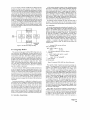
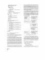
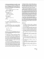
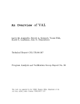
Verification of VHDL Designs Using VAL*
Larry M. Augustin, Benoit A. Gennart, Youm Huh,
David C. Luckham, and Alec G. Stanculescu
Computer Systems Laboratory
Stanford University
Stanford, California 94305
Abstract
VAL (VHDL Annotation Language) uses a small number of new
language constructs to annotate VHDL hardware descriptions. VAL
annotations, added to the VHDL entity declaration in the form of
formal comments, express intended behavior common to all architectural bodies of the entity. Annotations are expressed as parallel processes that accept streams of input signals and generate constraints
on output streams. VAL views signals as streams of values ordered
by time. Generalized timing expressions allow the designer to refer to
relative points on a stream. No concept of preemptive delayed assignment or inertial delay are needed when referring to different relative
points in time on a stream. The VAL abstract state model permits
abstract data types to be used in specifying history dependent device
behavior. Annotations placed inside a VHDL architectural body define detailed correspondences between the behavior specification and
architecture. The result is a simple but expressive language extension of VHDL with possible applications to automatic checking of
VHDL simulations, hierarchical design, and automatic verification
of hardware designs in VHDL.
1.0 Introduction
The VHSIC Hardware Description Language (VHDL) supports
the design, description, and simulation of VHSIC components [8]
It provides a base language that can be used to describe hardware
ranging from simple logic gates to complex digital systems. As an
IEEE standard [ll],VHDL will provide an important common base
language for design tool development and design documentation.
VHSIC designs will incorporate anywhere from a few hundred to
perhaps a million components. Managing this complexity requires
a powerful hardware design support environment including a library
manager, profiler, simulator, and other design tools. A key problem
which such environments must address is verifying the correctness
of a design. If current practice continues, the VHDL designer will
verify designs using a simulator and manually compare huge volumes
of simulator output with an informal design specification. For large
and complex designs, this is simply not practical
VHDL Annotation Language (VAL) [l] provides an annotation
facility that allows the VHDL designer to apply simple kinds of annotations during the design process. VAL annotations have several
possible applications, each of which may be supported by future environment tools. In this paper, we describe VAL and its application
to automatic checking of the correctness of a VHDL design during
simulation. Other applications of annotations, such as formal verification and optimization of simulation will be discussed in later
papers.
In general, annotation languages express information about various aspects of a program in machine readable form that is not normally part of the program itself [5]. They provide facilities for explaining the intended behavior of the program. They are intended
to reduce programming errors by making programs more readable
‘This work wa8 supported by the VHSIC Program Office, Department of the
Air Force (AFSC), under Contract F3361SS&C-1137
and by providing a great deal of error checking a t both compile and
run time. hadability is improved by enabling the programmer to
express design decisions explicitly. Explanations may also serve as
specification and thus precede implementation of the program.
VAL allows information about various aspects of a design that
may not normally be part of a VHDL description to be expressed
explicitly in a machine processable form. Intended behavior, design
decisions, and the correspondence between specification and implementation are expressed in a simple but powerful high level language
for annotating hardware behavior. Annotations are included in the
VHDL text as formal comments. This allows the annotated description t o be processed without modification by the VHDL analyzer. A
preprocessor, the VAL Transformer, translates VAL annotations into
VHDL source code resulting in a self-checking VHDL description.
In the remainder of this paper, we will first give an overview of
design checking using VAL. Then we will describe VAL in more detail, showing how VAL annotations are used to generate constraints
on a VHDL simulation. A brief overview of the VAL Transformer
demonstrates the feasibility of our design. We conclude with some
observations made from our experience with VAL to date, and areas
for future work.
2.0 Design Checking With VAL
A designer usually verifies a design using some form of simulation.
This task often requires the designer to manually compare the simulation result with an informal design specification. Occasionally, the
designer also has a high level behavioral description (written in, for
example, C or Ada) whose output can be compared to the output
of the simulator. The design is simulated using a set of test vectors,
the behavioral model is run on the same test vectors, and the results
are compared (Figure 1).
Simulation
output
,
I
Y
Structural
Simulation
I
Compare
1
Simulation
output
Figure 1: Typical Model of Design Checking
While this process of verification is adequate for simple designs,
as designs become more complex it becomes less satisfactory. It is
limited in the extent to which it allows the designer to debug a new
design because it assumes a “black box” view of the design unit (or
entity), in which the entity is accessible only through its ports.
VAL’S model of design checking is based on generating constraints
on the entity’s input, internal state, and output (Figure 2). Input
constraints allow the simulator to check if an entity is being used cor-
25th ACM/IEEE Design Automation Conference@
Paper 4.4
48
CH2540-3/88/0000/0048$01.OO 0 1988 IEEE
rectly. For example, if the setup or hold time on a signal is not met,
the entity can report an input constraint violation. This helps the
designer to spot the source of timing errors as opposed to having to
trace the source of the error back from the simulation result. Output
constraints behave like the post simulation comparison previously described, with the addition that they may be executed dynamically,
during the simulation. Mapping constraints allow an additional level
of internal checking beyond the checking of ports. For example, if
the behavioral description is a state machine, the states in the behavioral description must be somehow encoded within the structural
model. (i.e., distributed over the states of the lower level entities in
the architecture.) Mapping constraints allow the designer to explicitly describe the encoding and allow the simulator to automatically
check the internal state of the structure during simulation, rather
than forcing the designer t o deduce an incorrect state transition from
the simulation result.
Behavioral
Simulation
J
;t
onstraint
onstraint
cStructural
Simulation
qq
onstraint
c
A VAL interface annotation consists of a list of parallel processes
that execute continuously. Unlike typical programming languages
which execute a process once when it activates, a VAL process executes continuously while active. In many ways this is similar to
actual hardware behavior. For example, an AND gate does not behave by watching its inputs for a change and recomputing a new
output when a change occurs. Instead, it continuously performs the
AND operation. More formally, continuously means that the operation is performed so often that performing it any more frequently
would not produce any observable change in behavior.
The following sections summarize the most important kinds of
processes in VAL and then show how the VAL concept of relative
time, in conjunction with these processes, models hardware behavior.
3.1.1 Assertions
An assertion process generates constraints on the simulation. Consider the VHDL entity interface for a two input AND gate shown in
Figure 3. The identifiers input-a and input-b are input ports and
r e s u l t is the output port. Assertions in the form of VAL processes
are added to define the behavior of this circuit. The behavior of
the AND gate is specified by a single assert process that makes
an assertion about the value carried on the output port. The keywords b e h a v i o r and end b e h a v i o r delimit the VAL annotations
describing the entity's intended behavior. The assert process continuously checks a constraint (in this case ( i n p u t a and input-b)
= r e s u l t ) . It is similar to the assert statement in VHDL. If the
constraint ever evaluates to false, the assert process performs the
requested action.
Simulation
output
Figure 2: VAL Model of Design Checking
--
Annotated VHDL two input AND gate
entity TvoInputAND is
port (input-a, i n p u t b
3.0 Language Basics
VAL annotations may appear in all three VHDL design units; entities, architectures, and configurations. Interface annotations in the
entity declaration express intended behavior common to all architectural bodies of the entity. They define an abstract model of the
entity's internal state and use it, in conjunction with the inputs to
the entity, to define constraints on values carried by the output ports.
In VHDL, ports of mode out cannot be read within the entity and
therefore assertions cannot normally be made about them. Unlike
VHDL, VAL interface annotations have visibility over the contribution of the entity to each of its out ports. This allows the designer
to define the entity's contribution to the output port. Constraints
may also be defined on input ports.
Annotations within the VHDL architecture (body annotattons) can
be used to constrain the values of internal signals and ports of components. In addition, VAL annotations within the architecture have
visibility over the abstract state of the entity (defined by the interface
annotations) as well as the internal states of each component instantiated in the architecture. Annotations in an architecture relating to
state are known as mapping annotations. In effect, mapping annotations describe the way in which the abstract state introduced in the
interface annotations is mapped into the states of the architecture's
components.
Annotations appearing in a configuration (configuration annotattons) allow the user t o configure the VAL portion of the simulation.
For example, the user may want to to select only some of entities
in a large simulation for automatic checking. Also, the state model
map, similar to a VHDL port or generic map, can be used to map a
state model assumed for a component in an architecture into the actual state model of the actual component. This allows a designer to
assume an abstract state model for a component during design and
provide a type conversion function to translate the assumed state
model of the component to the state model of the actual component.
3.1 Interface Annotations
---I
--I
--I
--I
--I
result
:
:
in b i t ;
out b i t ) ;
VAL Annotations defining the AND gate's behavior
behavior
assert ( ( i n p u t 2 a n d input-b) = r e s u l t )
s e v e r i t y FAILURE
r e p o r t "Error i n TwoInputAND" ;
e n d behavior;
end TwoInputAND;
Figure 3: Annotated VHDL AND Gate Entity Declaration
VAL provides a family of assertion processes for generating constraints. The assert process is the strictest of these, requiring the
constraint to be satisfied at every simulation cycle (i.e. a t every
delta). In this sense it corresponds directly to the VHDL assert
statement. Perfectly correct behaviors will often violate this constraint because a zero delay signal assignment in VHDL occurs after
a delay of delta, limiting the usefulness of the VHDL assert statement
for checking this kind of behavior. Other VAL assertion processes
operate by generating constraints only at certain points during the
simulation. For example, the finally assertion process allows the
user to specify a constraint that must hold only at the last delta
in a simulation time point. The constraint generated by the annotation in Figure 4 will report an error for a single delta whenever a
change in i n p u t 2 or input-b causes a change in r e s u l t because the
VHDL simulation of any architecture for this entity does not effect
the change until the next delta. Replacing assert by finally checks
only after the assignment has been completed, reflecting more closely
the intentions of the designer.
Unlike VHDL, VAL provides the capability to hierarchically nest
assertions using a guarded process. The keyword w h e n identifies a
guarded process that consists of two lists of processes, corresponding
to a then part and an else part, and a boolean guard expression.
(See Figure 4.) The else part is optional. The guarded process continuously evaluates a boolean expression, and, if the expression is
Paper 4.4
49
architecture SIWLF, of TwoBitCounter is
signal 91. 9 2 , Qlbar, Q2bar : b i t ;
signal D1. D2 : b i t ;
Component DFlipFlop
port(Clk, D : i n b i t ;
9, Qbar : o u t b i t ;
Reset : in b i t ) ;
--I
state model is b i t ; -- local state model declaration
end component;
for a l l : DFlipFlop use
entity DFlipFlop (SIMF'LE) ;
--I
valentity;
-- use the transformed version of this
--I
valarchitecture; -- component for checking
begin
D F L l : DFlipFlop
port map(C1k. D 1 , 91, Qlbar, Reset);
DFL2 : DflipFlop
port map(Clk, D2. Q2. QZbar, Reset);
DZ <= (91 and Q2bar) o r (Qlbar and 92);
D 1 <- Clk;
architecture (named MONITOR) contains the VHDL translation of the
VAL annotations that appeared in the entity declaration. This includes the annotations which maintain the entity's state model. The
ports of architecture MONITOR are the same as for entity A with the
addition of an out port of the same type as the entity's state model.
This out port is used to provide visibility over the state of components of type A to any annotations within any architecture that
instantiates a component of type A. The generated entity A-OUTSTATE
describes the interface for MOBITOR.
Architecture MOBITOR contains a component SOCKET having the
same ports as entity A with the addition of an in port of the same
type as the entity's state model. A translated version of the original architecture body T of A is plugged into this socket. Because
the entity's state is passed into the SOCKET through a port, it is visible to annotations within the architectural body. The translated
version of T , TXXPANDED, contains a translation of the VAL annota
tions appearing in the architecture into VHDL. Its entity interface
is described by AINSTATE.
architecture S of
architecture SXXPANDED
TESTEENCE i s
TESTXNTITY : A;
of, TESTEENCE i s
component TESTJNTITY
A-OUTSTATE;
entity A is
-- entity A plus an
component
B i t 0 <= Ql;
B i t 1 <= 92;
-- mapping annotattons relate the state of the counter
--
e n t i t y A-OUTSTATE is
to the states of the components
--I
select state is
--I
0 => finally(DFLZ.state = '0' and DFLl.state = '0')
report "Counter s t a t e does n o t match flipflop s t a t e "
--I
--I
severity w a r n i n g ;
--I
1 => finally(DFL2.state = '0' and DFLl.state = ' 1 ' )
r e p o r t "Counter s t a t e does not match f l i p f l o p state"
--I
--I
severity w a r n i n g ;
--I
2 -> finally(DFL2.state
' 1 ' and DFLl.state = '0')
report "Counter s t a t e does not match flipflop state"
--I
severity warning;
--I
--I
3 => finally(DFL2.state = '1' and DFLl.state = '1')
report "Counter s t a t e does not match flipflop s t a t e "
--I
--I
severity warning;
--I end select;
end SIWLE;
--
--
V A L annotations
entity A plus an
-- additional i n pori
ATOUTSTATE i s
component SOCKET :
A-INSTATE ;
I
architecture T
of A i s
- - V A L Annotations
Figure 7: Twc-bit Counter Architecture
I
H
1
'
The VAL Transformer runs as a pre-processor on an annotated
VHDL description to generate a self-checking VHDL description.
additional out port
--
-
4.0 VAL Transformer
:
I
I
architecture TIXPANDED
of AINSTATE i s
-- V H D L translation
--of V A L annotations
I
I
I
Figure 8: Relationship Between Design Units
4.1 Structure of the Translation
4.2 Translation of Major Language Constructs
The translation algorithm is based on the generation of an additional architecture called the MONITOR that contains an instantiation
of the architecture under test and can check its outputs using the assertions in the entity declaration. The concept is similar to plugged
a device into a bed of nails for testing. The monitor body has visibility over all signals traveling between the actual entity body and
the other components in the simulation. One advantage of this approach is that VAL assertions can also measure the contribution of
the entity body's outputs to their environment. A difficult problem
in the translation is providing visibility over the component's state
needed for the mapping annotations. This is solved by creating an
additional port in the entity declaration and passing the state on the
port.
Given the environment for handling scoping and visibility among
design units described above, a translation algorithm can be given
for each of the language constructs in VAL. The complete details of
the VAL to VHDL translation can be found in [7]. The translation
mechanism for the f i n a l l y assertion and time qualified assertions
are presented here to give the general flavor of the translation process.
The design units involved in the translation are shown in Figure 8.
Assume an entity A exists containing VAL annotations. Three design
units are generated; two entity declarations and an architecture. The
Paper 4.4
52
4.2.1 Translation of Finally Assertion
The general form of the finally assertion is:
finally <test-expression>
C report <message-erpression>l
C severity <severity_expression>] ;
Within the MONITOR architecture a process is created for each finally assertion. (See Figure 9.) This process is sensitive to all of
--
DFlipFlop entity specification
entity DFlipFlop is
generic (SETUP, HOLD, DELAY : P o s l n t e g e r ) ;
port (Clk : in b i t ; -- Clock input
D
: in b i t ;
-- Data input
Q
: out b i t ;
-- Output
Qbar : out b i t ) ;
--I s t a t e model is b i t ; -- A single bit of memory
--I behavior
---I
--I
---I
--I
--I
--I
--I
--I
---I
--I
--I
Assertions about generics
assert (DELAY >= HOLD)
report “Error i n generic constant“ ;
State maintenance
when (Clk’Changed(’0’) then
when (D’Stable during C-SETUP, HOLD])
then D -> StateCDELAYl ;
else report “Data not stable“ ;
e n d when;
e n d when;
Check outputs
assert ((State =
Q)
a n d (not State = Qbar))
report “Simulator error
-D
latch” ;
end behavior;
end DFlipFlop;
Figure 5: Annotated D Flip-Flop Entity Declaration
Clk’Changed( ’0’) becomes true, the guarded process checking the
setup and hold time of the data becomes active. Note that the
expression during C-SETUP, BOLD] checks the interval SETUP time
units in the past and BOLD time units in the future. If the data remains stable over this interval, the internal state of the D flip-flop is
modified after a time DELAY. The assertion processes constrains the
ports of the VHDL body t o match the state bit, and its negation, a t
all times.
The constraint DELAY >= HOLD is worth exploring further. Conceptually, this implies that the output can never take on a new value
before that new value is latched into the internal state. If DELAY <
HOLD were true, then the output could change after DELAY time units,
but the hold constraint might not yet be met, in which case the output value should never have changed. In other words, if DELAY <
HOLD then the behavior is non-causal. This is more obvious if the
VAL description in Figure 5 is rewritten such that the reference point
is the point a t which the state is assigned a new value. The relevant
lines become,
when D’stable
d u r i n g C-SETUP-DELAY, HOLD-DELAY]
then
D [-DELAY] -> s t a t e CO] ;
end when;
If HOLD-DELAY > 0, then the assignment to the new value of state
depends on an event that hasn’t happened yet - the stability of the
input during the hold time.
3.2 Body and Mapping Annotations
Any of the VAL processes, with the exception of drive, can appear
in the entity body. Body annotations specify implementation details
and allow more detailed consistency checking between the interface
annotations (the entity’s functional description) and the VHDL architecture (implementation). Body annotations have visibility over
all VHDL signals and ports normally visible at the point a t which the
annotation appears, the entity’s state model, and the state models
of all entities instantiated as components.
The description of the two-bit modulo four counter in Figures 6
and 7 together show how mapping annotations may be used to check
the internal state of an entity. The reset signal sets the state of
the counter. Whenever a transition from ’1’ to ’0’ on the clock
(Clk) occurs, the counter counts up one. B i t O represents the least
significant bit of the counter and B i t l the MSB. The VAL state
model is an integer and assert processes generate constraints on the
output ports based on the VAL state.
entity TwoBitCounter is
port (Clk
: in b i t ;
: in b i t ;
reset
BitO. B i t l
: out b i t ) ;
--I s t a t e model is integer;
--I behavior
--I
when r e s e t then
--I
s t a t e <- 0 ;
--I
elsewhen Clk’changed(’0’) then
--I
s t a t e <- (state + 1) mod 4;
--I
e n d when;
--I
select s t a t e is
0 => f i n a l l y ( B i t 0 = ’0’ a n d B i t l = ’0’)
--I
--I
--I
--I
--I
--I
--I
--I
--I
--I
--I
--I
--I
--I
report “Counter
-
Output error“;
s e v e r i t y warning;
a n d B i t l = ’0’)
1 => f i n a l l y ( B i t 0 = ’ 1 ’
report “Counter
-
Gutput error“;
s e v e r i t y warning;
2 => finallyCBit0 = ’ 0 ’ a n d B i t l = ’ 1 ’ )
report “Counter
-
Output error“;
s e v e r i t y warning;
3 => finallyCBit0 = ’1’ a n d B i t l = ’ 1 ’ )
report “Counter
-
Output error“;
s e v e r i t y warning;
e n d select;
e n d behavior;
end TwoBitCounter;
Figure 6: Two-bit Counter Entity Declaration
The architecture SIMPLE of the counter contains two D-type flipflops. Each flip-flop is similar to the ones described previously with
the exception of a reset signal and the omission of timing information
(to keep the examples short enough to fit in this paper). Each flipflop has a state model consisting of a single bit. The states of the
flip-flops (DF’LI.state and DFL2.state) are related to the state of
the counter ( s t a t e ) by mapping annotations.
3.3 Configuration Annotations
Configuration annotations serve two purposes. First, they provide
a local state model mapping declaration to map the local state model
defined in a component declaration to the actual state model defined
by the component’s interface annotations. The state model mapping
declaration indicates the function to use in mapping between the
state model of the actual entity and the state model of the component
instance. It appears within a configuration specification at the same
point as other binding indications.
Second, they provide Configuration information so that VAL generated architectures may be automatically substituted for original
component architectures for checking. The user may not want to
use a VAL annotated entity in place of the original VHDL entity for
all components in a simulation, particularly if the component is a library unit for which no annotated description exists. The v a l e n t i t y
construct allows the user to select the components of an architecture
to be monitored. The VAL Transformer will only generate code to
monitor components marked with v a l e n t i t y . The next section on
the VAL Transformer explains how components are monitored.
Paper 4.4
51
architecture SIWLE of T s o B i t C o u n t e r is
signal 91, 92, Qlbar, Qlbar : b i t ;
signal D1. D2 : b i t ;
component DFlipFlop
port(Clk, D : i n b i t ;
9 . Qbar : out b i t ;
Reset : in b i t ) ;
--I
state model is b i t ; -- local state model declaration
end component ;
for all: DFlipFlop use
entity DFlipFlop (SIMPLE);
--I
valentity;
-- use the transformed version of this
--I
valarchitecture; -- component for checking
begin
D F L l : DFlipFlop
port map(Clk, D 1 , Q l ,Qlbar. Reset);
DFL2 : DflipFlop
port rap(C1k. D2. 92. Qlbar, Reset);
architecture (named MOIIITOR) contains the VHDL translation of the
VAL annotations that appeared in the entity declaration. This includes the annotations which maintain the entity's state model. The
ports of architecture MOIIITOR are the same as for entity A with the
addition of an out port of the same type as the entity's state model.
This out port is used to provide visibility over the state of components of type A to any annotations within any architecture that
instantiates a component of type A. The generated entity A-OUTSTATE
describes the interface for MOIIITOR.
Architecture MOIIITOR contains a component SOCKET having the
same ports as entity A with the addition of an in port of the same
type as the entity's state model. A translated version of the original architecture body T of A is plugged into this socket. Because
the entity's state is passed into the SOCKET through a port, it is visible to annotations within the architectural body. The translated
version of T, TXXPANDED, contains a translation of the VAL annota
tions appearing in the architecture into VHDL. Its entity interface
is described by AINSTATE.
architecture
S
of
TESTEENCE
is
...
D2 <= (91 and Q2bar) or (Qlbar and 92);
D 1 <= C l k ;
B i t 0 <= 91;
B i t 1 <= 92;
component
TESTXNTITY : A;
architecture SXXPANDED
-
of, TESTEENCH is
component TESTXNTITY :
A-OUTSTATE;
-- mapping annotations relate the d a t e of the counter
-- to the states of the components
--I select state is
--I
0 => finally(DFL2.state = '0' and DFLl.state = '0')
report "Counter s t a t e does n o t match f l i p f l o p s t a t e "
--I
--I
--I
--I
--I
--I
--I
--I
--I
--I
--I
severity warning;
finally(DFL2.state = '0' and DFLl.state = ' 1 ' )
report "Counter s t a t e does not match f l i p f l o p s t a t e "
severity saming;
2 -> finally(DFLZ.state
'1' and DFLl.state = '0')
report "Counter s t a t e does not match flipflop state"
severity warning;
3 => finally(DFL2.state = '1' and DFLl.state = '1')
1 =>
-
4
architecture MONITOR of
?,OUTSTATE i s
component SOCKET :
A-INSTATE;
r e p o r t "Counter s t a t e does n o t match f l i p f l o p s t a t e "
severity warning;
--I end select;
end SIWLE;
-
I
I
'
Figure 7: Two-hit Counter Architecture
4.0 VAL Transformer
The VAL Transformer runs as a pre-processor on an annotated
VHDL description to generate a self-checking VHDL description.
architecture T
of A i s
- - V A L Annotations
I
H
I
architecture TXXPANDED
of AlNSTATE i s
-- V H D L translation
--of V A L annotattons
I
Figure 8: Relationship Between Design Units
I
4.1 Structure of the Translation
4.2 Translation of Major Language Constructs
The translation algorithm is based on the generation of an additional architecture called the MONITOR that contains an instantiation
of the architecture under test and can check its outputs using the assertions in the entity declaration. The concept is similar to plugged
a device into a bed of nails for testing. The monitor body has visibility over all signals traveling between the actual entity body and
the other components in the simulation. One advantage of this approach is that VAL assertions can also measure the contribution of
the entity body's outputs to their environment. A difficult problem
in the translation is providing visibility over the component's state
needed for the mapping annotations. This is solved by creating an
additional port in the entity declaration and passing the state on the
port.
Given the environment for handling scoping and visibility among
design units described above, a translation algorithm can he given
for each of the language constructs in VAL. The complete details of
the VAL to VHDL translation can he found in [7]. The translation
mechanism for the f i n a l l y assertion and time qualified assertions
are presented here to give the general flavor of the translation process.
The design units involved in the translation are shown in Figure 8.
Assume an entity A exists containing VAL annotations. Three design
units are generated; two entity declarations and an architecture. The
Paper 4.4
52
4.2.1 Translation of Finally Assertion
The general form of the finally assertion is:
finally <test-expression>
[
report <message_expression>l
[
severity <severity~expression>l;
Within the MONITOR architecture a process is created for each finally assertion. (See Figure 9.) This process is sensitive to all of
the signals in the <test-expression> and , in addition, to a wakeup signal VAL-CBE. When the process is activated due to a change
in one of the signals in <test-expression>, it remembers the new
value of <test-expression> and sets the signal VAL-CBE t o wake
itself up a t the beginning of the next time point to check the remembered value of <test-expression>. The remembered value of
<test-expression> will be the value set a t the end of all the deltas
in the previous simulation point.
process ( <test-expression sensitivity list>.VAL-CBE
variable OLDB : BOOLEAN := TRUE;
v a r i a b l e I B : BOOLEAN :- TRUE;
begin
if not VAL-GBE’QUIET then
assert OLDB
r e p o r t <message-expression>
severity <severity-expression>;
end if;
I B :s <testsxpression>;
if (IB /= OLDB) then
)
OLDB := m ;
VAL-GEE <= not VALSBE a f t e r I f s ;
end if;
e n d process;
Figure 9: Translation of Finally
4.2.2 Translation of Time Qualified Expressions
In general, a time qualified boolean expression will have the following form:
expr during [Tl,T2]
This is translated into VHDL by creating a virtual signal (GBExpr)
driven by the boolean expression and then checking the stability of
the signal over the requested time interval. The translation looks
like:
signal GBExpr : boolean;
...
GBExpr
<= expr
;
GBExpr’STABLE(T2 - T I )
Recall that T2 >= Ti in the time qualified boolean expression, and
therefore the argument of the attribute ’STABLE must be positive or
zero. Nested time qualified expressions generate successive applications of the ’STABLE attribute.
5.0 Experience, Status, and Future Work
The VAL Transformer is currently under development. A prototype transformer for a subset of VAL is currently running with
VHDL 7.2. We are currently implementing a VHDL 1076 version
of the Transformer. Very preliminary experiments show that annotat,ions in general may slow down the simulation by 20% t o 70%,
depending of the extent of their use. VAL provides a mechanism
(the configuration annotations) for selecting the components that
are monitored. This allows the user to select the level of checking
necessary for a given application.
VAL has been used in the design and debugging of several benchmarks of moderate size. These include the traffic light controller
specified in [6] and described in VHDL in [9], the two-bit counter
from which earlier examples have been taken, the ALU in [IO], and
a simple 16-bit CPU. In all cases the VAL annotation has provided
a clean and simple specification of the intended behavior. Perhaps
more importantly, the design checking provided by VAL significantly
increased our confidence in the correctness of the design. In one instance (the two-bit counter described earlier), an outright design
bug missed by the designer in reviewing the VHDL simulation output was flagged and quickly located when the same simulation was
automatically checked using VAL. Mapping annotations were particularly useful in isolating the cause of the error. The reason for
this is that they allow the subcomponent(s) related to an error to
be immediately identified, since an error is detected as soon as an
assertion is violated, not just a t the outputs of a component.
Currently we are focusing on gaining more experience with annotating larger benchmarks. Language extensions such as additional
abstraction mechanisms may be necessary for large and complex entities. Additional kinds of annotations, such as package, type and
subtype constraints akin to those in (51 might also be useful. While
the current mapping annotations have so far proved adequate, their
coarse granularity doesn’t provide the detailed level of constraint
checking that might be needed. As an aid in debugging, A means
of enabling and disabling more detailed assertions would be useful.
Finally, VAL’S semantics were kept simple to allow the potential application of formal verification methods [2,3]. Formal verification
would provide a degree of verification beyond or perhaps in addition
to the current model of simulation time constraint checking.
We view VAL as a trend in hardware design languages, and not
as a finished project. The next development will probably be constructs for expressing design hierarchy. These are clearly required,
even to develop our current VAL checker into a design debugger for
use with VHDL simulators. Hierarchy constructs are quite clearly
needed to pursue more ambitious applications of design languages
such as mathematical verification of designs and (semi-automatic or
interactive) synthesis.
References
[l] L. M. Augustin, B. A. Gennart, Y. Huh, D. C. Luckham, and
A. G. Stanculescu. VAL: An annotation language for VHDL.
In ICCAD ’87 Digest of Technical Papers, pages 418-421, Santa
Clara, CA, November 1987.
[2] 0. J . Dahl. Can Program Proving be Made Practical? Technical
Report, Institute of Informatics, University of Oslo, May 1978.
[3] M. Gordon. How to Specifg and Verify Hardwam Using Higher
Order Logic. Lecture Notes, University of Texas at Austin, 1984.
[4] D. C. Luckham, A. Stanculescu, Y . Huh, and S.Ghosh. The semantics of timing constructs in hardware description languages.
In ICCD ’88, pages 10-14, Port Chester, New York, October
1986.
[5] D. C. Luckham and F.W. vonHenke. An overview of ANNA,
a specification language for Ada. IEEE Software, 2(2):9-22,
March 1985.
[6] C. Mead and L. Conway.
Addison-Wesley, 1980.
Introduction to VLSI Systems.
[7] A. G. Stanculescu. VHDL Annotation Language (VAL): Transformation of Annotated Entities. Technical Report under preparation, Computer Systems Laboratory, Stanford University,
1987.
[8]
VHDL Design Analysis and Justification.
1984. IR-MD-018-1.
[9]
VHDL User’s Manual: Volume 111 - Benchmarks. Iutermetrics,
Inc., 4733 Bethesda Ave., Bethesda, MD 20814, July 1984. IRMD-029.
Intermetrics, July
[lo] VHDL User’s Manual: Volume I - Tutorial. Intermetrics, Inc.,
4733 Bethesda Ave., Bethesda, MD 20814, August 1985. IRMD-065-1.
[Ill VHDL Language Reference Manual:
ior6/~.1987.
IEEE Draft Standard
Paper 4.4
53