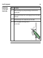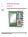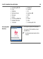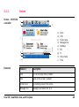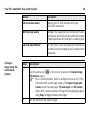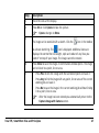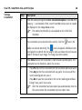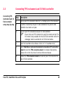
1
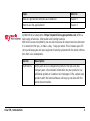
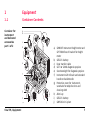
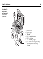
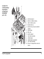
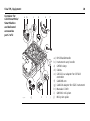
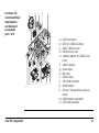
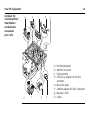
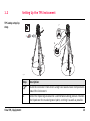
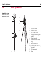
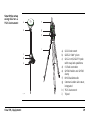
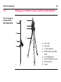
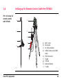
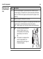
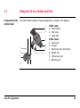
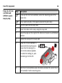
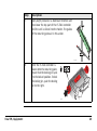
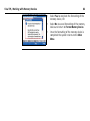
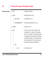
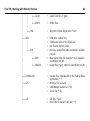
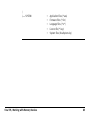
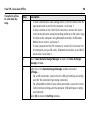
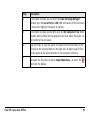
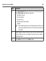
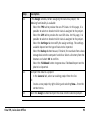
Leica Viva TPS
Getting Started Guide
Version 3.0
English
2
Viva TPS, Introduction
Introduction
)
)
Purpose of this
manual
Quick references
to specific topics
To use the products in a permitted manner, please refer to the detailed safety
instructions in the Leica CS10/CS15 User Manual, Leica GS10/GS15 User Manual, Leica
TS11/TS15 User Manual and Leica TPS1200+ User Manual.
For detailed descriptions of all functions and settings of the product and applications,
please refer to the Leica Viva Series Technical Reference Manual.
This Getting Started Guide is intended as a quick field reference manual for immediately getting started with your Leica Viva Series equipment. The manual explains what
you can find in your container, how everything fits together and how to get started
on the basic applications.
Topic
Refer to
What’s in my container?
Chapter 1.1
How does the equipment all fit together?
Chapter 1.2
What is this first screen I see when I turn on my instrument?
Chapter 2.1
How do I get to the Main Menu?
Chapter 2.1
How do I select things and move around the screens?
Chapter 2.2
What are wizards?
Chapter 2.2
Topic
Refer to
How do I get started with jobs and codelists?
Chapter 3
How to use the applications?
Chapter 4
myWorld@Leica Geosystems (https://myworld.leica-geosystems.com) offers a
wide range of services, information and training material.
With direct access to myWorld, you are able to access all relevant services whenever
it is convenient for you, 24 hours a day, 7 days per week. This increases your efficiency and keeps you and your equipment instantly updated with the latest information from Leica Geosystems.
Viva TPS, Introduction
Service
Description
myProducts
Simply add all Leica Geosystems products that you and your
company own. View detailed information on your products, buy
additional options or Customer Care Packages (CCPs), update your
products with the latest software and keep up-to-date with the
latest documentation.
3
4
Viva TPS, Introduction
Service
Description
myService
View the service history of your products in Leica Geosystems
Service Centers and detailed information on the services performed
on your products. For your products that are currently in Leica
Geosystems Service Centers view the current service status and the
expected end date of service.
mySupport
Create new support requests for your products that will be
answered by your local Leica Geosystems Support Team. View the
complete history of your Support and view detailed information on
each request in case you want to refer to previous support
requests.
myTraining
Enhance your product knowledge with the Leica Geosystems
Campus - Information, Knowledge, Training. Study the latest online
training material or download training material on your products.
Keep up-to-date with the latest News on your products and
register for Seminars or Courses in your country.
Table of Contents
In this manual
Chapter
1
Equipment
1.1
1.2
1.3
1.4
1.5
1.6
1.7
2
Page
Container Contents
Setting Up the TPS Instrument
Setting Up SmartStation
Setting Up SmartPole
Setting up for Remote Control (with the RadioHandle)
Setting up for Remote Control (with the TCPS28)
Fixing the CS to a Holder and Pole
SmartWorx Viva and Principles
2.1
2.2
2.3
Viva TPS, Table of Contents
SmartWorx Viva
2.1.1
Screen
2.1.2
Icons
2.1.3
Main Menu
2.1.4
Leica Favourites
Operating Principles
Connecting TPS instrument and CS field controller
7
7
13
15
18
20
21
23
27
27
29
33
37
40
43
49
5
6
Viva TPS, Table of Contents
3
Jobs & Data
3.1
3.2
3.3
4
Creating a New Job
Creating a Codelist
Importing ASCII Data into a Job
Applications
4.1
4.2
4.3
4.4
Setup
Survey
Stakeout
Reference Line
Appendix A
A.1
A.2
Working with Memory Devices
Formatting a Memory Device
Directory Structure of the Memory Device
50
50
52
57
61
62
69
72
77
80
80
83
Appendix B
Uploading System Files
86
Appendix C
Leica Geo Office
89
1
Equipment
1.1
Container Contents
Container for
instrument
and delivered
accessories
part 1 of 2
a
b
c
d
e
f
g
h
TS_052
Viva TPS, Equipment
i
j
a) GHM007 Instrument height meter and
GHT196 tribrach bracket for height
meter
b) GEB221 battery
c) Data transfer cable
d) GFZ3 or GOK6 diagonal eyepiece
e) Counterweight for diagonal eyepiece
f) Instrument with tribrach and standard
handle or RadioHandle
g) Protective cover for instrument,
sunshade for objective lens and
cleaning cloth
h) Allen key
i) GEB221 battery
j) GMP101 mini prism
7
8
Viva TPS, Equipment
Container for
instrument
and delivered
accessories
part 2 of 2
a
b
c
e
d
f
TS_053
g
a)
b)
c)
d)
e)
f)
g)
Pocket knife
Spare stylus
Manuals
2 x SD cards and covers
Tip for mini prism
GKL211 battery charger
Car adapter power plug for battery
charger (stored under battery
charger)
Container for
GS15 SmartPole/
SmartStation
and delivered
accessories
part 1 of 2
a
b
c
d
a)
b)
c)
d)
e)
f)
g)
h)
i)
j)
k)
l)
m)
e fgh
SYS_019
Viva TPS, Equipment
i j
k
l
m
GS15 instrument
GEB211 / GEB212 battery
GRZ4 / GRZ122 prism
Radio antennas
GRZ101 mini prism and GAD103
adapter
Spare stylus
Allen key
GAD31 adapter
CS10 field controller
GHT62 holder
GHT62 holder (extended)
CS15 field controller
SD card / CompactFlash card and
covers
9
10
Viva TPS, Equipment
Container for
GS15 SmartPole/
SmartStation
and delivered
accessories
part 2 of 2
a
b
c
d
e
f
a)
b)
c)
d)
e)
SYS_020
g
h
i
j
RH15 RadioHandle
Instrument carry handle
GHT63 clamp
Cables
GDC221 car adapter for CS field
controller
f) GAD108 arm
g) GAD110 adapter for GS15 instrument
h) Manuals & DVD
i) GMP101 mini prism
j) Mini prism spike
Container for
GS12 SmartPole/
SmartStation
and delivered
accessories
part 1 of 2
b
c
d
e
R
TRK
BT
PW
ON
OFF
a
a)
b)
c)
d)
e)
SYS_033
f gh i
j k
l
m
n
f)
g)
h)
i)
j)
k)
l)
m)
n)
Viva TPS, Equipment
GS12 instrument
GEB211 / GEB212 battery
GRZ4 / GRZ122 prism
GRZ101 mini prism
GAD103 adapter for GRZ101 mini
prism
GAD31 adapter
Spare stylus
Allen key
GHT63 clamp
CS10 field controller
GHT62 holder
SD card / CompactFlash card and
covers
GHT62 holder (extended)
CS15 field controller
11
12
Viva TPS, Equipment
Container for
GS12 SmartPole/
SmartStation
and delivered
accessories
part 2 of 2
a
b
c
d
e
a)
b)
c)
d)
SYS_034
f
g
h
RH15 RadioHandle
GMP101 mini prism
Field controller
GDC221 car adapter for CS field
controller
e) Mini prism spike
f) GAD104 adapter for GS12 instrument
g) Manuals & DVD
h) Cables
1.2
Setting Up the TPS Instrument
TPS setup step-bystep
7
2
3
6
1
1
5
1
5
4
5
TS_064
Step
)
1.
Viva TPS, Equipment
Description
Shield the instrument from direct sunlight and avoid uneven temperatures
around the instrument.
Extend the tripod legs to allow for a comfortable working posture. Position
the tripod over the marked ground point, centring it as well as possible.
13
14
Viva TPS, Equipment
Step
Description
2.
Fasten the tribrach and instrument onto the tripod.
3.
Turn on the instrument by pressing
. Select Main Menu/Instrument/TPS settings/Level bubble & compensator to activate the laser
plummet and electronic level.
4.
Move the tripod legs (1) and use the tribrach footscrews (6) to centre the
plummet (4) over the ground point.
5.
Adjust the tripod legs to level the circular level (7).
6.
By using the electronic level, turn the tribrach footscrews (6) to level the
instrument precisely.
7.
Centre the instrument precisely over the ground point (4) by shifting the
tribrach on the tripod plate (2).
8.
Repeat steps 6. and 7. until the required accuracy is achieved.
1.3
Setting Up SmartStation
SmartStation
setup step-by-step
TS_059
Viva TPS, Equipment
Step
Description
1.
Place the adapter for the GS15/GS12 instrument onto the instrument by
simultaneously pressing and holding-in the four push buttons.
15
16
Viva TPS, Equipment
Step
)
TS_060
Description
Ensure that the interface connection on the underside of the adapter is on
the same side as the Communication side cover.
Viva TPS, Equipment
Step
Description
2.
Place the GS15/GS12 instrument onto the adapter by simultaneously
pressing and holding-in the two press clips.
17
18
Viva TPS, Equipment
1.4
SmartPole setup
using GS15 on a
TS15 instrument
Setting Up SmartPole
a
b
g
c
h
i
j
d
e
f
TS_061
a)
b)
c)
d)
GS15 instrument
RTK slot-in device
GRZ122 360° prism
GLS30 pole with snap-lock
positions
e) CS field controller
f) GHT62 holder and GHT63
clamp
g) RH15 RadioHandle
h) Communication side cover,
integrated
i) TS15 instrument
j) Tripod
SmartPole setup
using GS12 on a
TS15 instrument
a
f
b
g
h
i
c
d
e
TS_128
Viva TPS, Equipment
a) GS12 instrument
b) GRZ122 360° prism
c) GLS12 cm/GLS12F ft pole
with snap-lock positions
d) CS field controller
e) GHT62 holder and GHT63
clamp
f) RH15 RadioHandle
g) Communication side cover,
integrated
h) TS15 instrument
i) Tripod
19
20
Viva TPS, Equipment
1.5
TPS / CS setup for
remote control
with RadioHandle
Setting up for Remote Control (with the RadioHandle)
e
a
f
g
b
h
c
d
TS_063
a)
b)
c)
d)
360° prism
Prism pole
CS field controller
GHT62 holder and GHT63
clamp
e) RH15 RadioHandle
f) Communication side cover
g) TPS instrument
h) Tripod
1.6
TPS / CS setup for
remote control
with TCPS28
Setting up for Remote Control (with the TCPS28)
a
e
b
f
g
c
h
d
i
TS_062
Viva TPS, Equipment
a)
b)
c)
d)
360° prism
Prism pole
CS field controller
GHT62 holder and GHT63
clamp
e) TPS instrument
f) Tripod
g) TCPS28
h) External battery
i) Y-cable
21
22
Viva TPS, Equipment
Step
Description
1.
The GHT43 tripod adapter is used to mount the TCPS28 to all Leica
standard tripods, and to optimise the radio transmission performance.
Attach the TCPS28 to the adapter and then attach the adapter to the
tripod leg.
2.
Adjust the angle of TCPS28 until it is vertical.
3.
Adjust the location of the adapter on the tripod leg so that there are no
metallic objects in the horizontal plane around the antenna.
Metallic objects near the antenna disturb radio transmissions.
)
)
)
To achieve the best performance
from the TCPS28, mount it in a
vertical position on the tripod leg,
approximately 30 cm from the
top.
If the adapter is no longer able to
retain its angle position, the
adjustment bolt at the hinge can
be tightened slightly.
cm
4.
~ 30
Mount base radio
to tripod step-bystep
TS_065
1.7
Fixing the CS to a Holder and Pole
Components of the
GHT62 holder
The GHT62 holder consists of some components, as shown in the diagram.
d
e
f
g
a
b
c
h
i
GHT63 clamp
a) Plastic sleeve
b) Pole clamp
c) Clamp bolt
GHT62 holder
d) Locking pin
e) Top clip
f) Mounting plate (extendable)
g) Bottom clip
h) Tightening screw
i) Mounting arm
TS_058
Viva TPS, Equipment
23
24
Viva TPS, Equipment
Fixing the CS field
controller and
GHT62 to a pole
step-by-step
Step
)
)
Description
If you use the CS15 field controller, extend the mounting plate of the
holder first.
For an aluminium pole, fit the plastic sleeve to the pole clamp.
1.
Insert the pole into the clamp hole.
2.
Attach the holder to the clamp using the clamp bolt.
3.
Adjust the angle and the height of the holder on the pole to a comfortable
position.
4.
Tighten the clamp with the clamp bolt.
5.
Before the CS field controller is
placed onto the mounting plate,
ensure that the locking pin is
put into the unlocked position.
To unlock the locking pin, push
the locking pin to the left.
6.
Hold the CS field controller above the holder and lower the end of the CS
field controller into the mounting plate.
TS_055
Step
Description
7.
Apply slight pressure in a downward direction and
then lower the top part of the CS field controller
until the unit is clicked into the holder. The guides
of the mounting plate aid in this action.
TS_056
8.
After the CS field controller is
placed onto the mounting plate,
ensure that the locking pin is put
into the locked position. To lock
the locking pin, push the locking
pin to the right.
TS_054
Viva TPS, Equipment
25
26
Viva TPS, Equipment
Detaching the
CS from a pole
step-by-step
Step
Description
1.
Unlock the locking pin by pushing the locking pin to the left of the
mounting plate.
2.
Place palm over the top of the CS until fingers grip the bar of the holder
underneath.
3.
Push from the top of the CS toward the bar of the holder.
4.
While in this position, lift the top of the CS
from the holder.
1
TS_057
2
2
SmartWorx Viva and Principles
2.1
SmartWorx Viva
Keyboard
TS11/TS15
1
2
3
ABC
4
5
7
8
6
MNO
9
TUV
0
WXYZ
.
a
b
c
d
e
f
g
h
i
j
k
OK
Fn
TS_087
Viva TPS, SmartWorx Viva and Principles
l
m
n
o
p
q
r
27
28
Viva TPS, SmartWorx Viva and Principles
a)
b)
c)
d)
e)
f)
g)
h)
i)
Start using SmartWorx Viva
Function keys F7 - F9
± key
Brightness
Alphanumeric keys
Backspace
Volume
Function keys F10 - F12
Keyboard illumination
Screenshot
j)
k)
l)
m)
n)
o)
p)
q)
r)
•
•
Windows CE
Favourites
ESC
Arrow keys, OK
ENTER
Fn
ON/OFF
Home
Function keys F1 - F6
Turn on your GS GNSS or TPS instrument.
Turn on your CS field controller and start
SmartWorx Viva.
For information about wizards refer to
"Wizards".
)
2.1.1
Screen - CS15 field
controller
Screen
a
b
f
c
g
h
i
d
e
SYS13_028
Elements
Element
Description
Time
The current local time is shown.
Title
Name of the screen is shown.
Screen area
The working area of the screen.
Message line
Messages are shown for 10 s.
Viva TPS, SmartWorx Viva and Principles
a)
b)
c)
d)
e)
f)
g)
h)
i)
Icons
Title
Screen area
Message line
Softkeys
ESC
Fn
Entry mode
Time
29
Viva TPS, SmartWorx Viva and Principles
30
Element
Description
Icons
Shows status information of the instrument. Refer to "2.1.2
Icons". Can be used with touch screen.
ESC
Can be used with touch screen. Same functionality as the fixed
key ESC. The last operation will be undone.
Entry mode
The caps mode for upper case letters is active. The caps mode is
activated and deactivated by pressing the CAPS key.
Fn
Switches between the first and second level of function keys.
Softkeys
Commands can be ran using F1-F6 keys (only applicable for CS15
field controller). The commands assigned to the softkeys are
screen-dependent. Can be used directly with touch screen.
Common softkeys
The softkeys following are used commonly in the Leica SmartWorx Viva software
across all applications.
Softkey
Function Key
Description
OK
(F1)
To select the highlighted option and to continue with
the subsequent screen.
Page
(F6)
To change to another page on the current screen.
Help
Fn (F1)
To open the Leica SmartWorx Viva online help.
Home
Fn (F2)
To move the focus to the top of the list shown in the
current screen.
End
Fn (F3)
To move the focus to the bottom of the list shown in
the current screen.
Quit
Fn (F6)
To exit the current application and return to the
screen from where the application was accessed.
Viva TPS, SmartWorx Viva and Principles
31
32
Viva TPS, SmartWorx Viva and Principles
Key combinations
Key
Function
Fn
+
1
Hold Fn while pressing 1. Increase the screen brightness.
Fn
+
3
Hold Fn while pressing 3. Increase the volume for
acoustic warning signals, beeps and keypresses on the
CS field controller.
Fn
+
4
Hold Fn while pressing 4. Decrease the screen brightness.
Fn
+
6
Hold Fn while pressing 6. Decrease the volume for
acoustic warning signals, beeps and keypresses on the
CS field controller.
Fn
+
0
Hold Fn while pressing 0.
If keyboard illumination is already off:
Turns on keyboard illumination.
If keyboard illumination is already on:
Turns off keyboard illumination.
Fn
+
.
Hold Fn while pressing .. Take a screenshot of the
current SmartWorx Viva screen.
Refer to "Taking a screenshot".
2.1.2
Icons
Description
The screen icons display the status information of the instrument.
)
The icons provide information related to basic instrument functions. The icons that
appear depend upon which instrument is used and the current instrument configuration.
Icon bar - TPS Mode
a
b
c
d
e
f
g
h
i
SYS13_026
a)
b)
c)
d)
Automatic aiming
Prism
Measure mode
Instrument face I&II/Compensator
level
e) Current active instrument
Viva TPS, SmartWorx Viva and Principles
f) Camera
g) Line/area/auto points
h) Memory storage (SD card/USB
stick/internal memory)
i) Battery level (field controller/instrument)
33
34
Viva TPS, SmartWorx Viva and Principles
Icons
Icon
Description
Automatic aiming
Displays the current automatic aiming, PowerSearch or
prism search/lock settings.
Prism
Displays the selected prism.
Measure mode
Displays the selected measurement mode. The red laser
icon will display when the red laser is active.
Compensator level and
instrument face I or II
Displays the compensator off or out of range icons, or
the instrument face I or II icon.
Current active instrument
Displays the instruments that are currently configured
and active. When more than one instrument is configured, the instrument at the front of the icon is the active
instrument.
GNSS specific icons
Icon
Description
Camera
Select this icon to begin the camera function.
Data management
Select this icon to open the data management pages for
Points, Lines or Areas. If there are open lines or areas,
a symbol will appear in the icon.
Memory storage
Displays the status of the internal memory or data
storage device.
Battery
Displays the status and location of the battery.
Icon
Description
Position status
Displays the status of the current position. As soon as
this icon becomes visible the instrument is in a stage
where practical operation can commence.
Viva TPS, SmartWorx Viva and Principles
35
36
Viva TPS, SmartWorx Viva and Principles
Icon
Description
Number of visible satellites
Displays the number of theoretically visible satellites
above the configured cut-off angle according to the
current almanac.
Contributing satellites
Displays the number of satellites that are contributing to
the currently computed position solution.
The number of contributing satellites can differ
from the number of visible satellites. This difference can be because satellites cannot be viewed,
or because the observations to these satellites
are considered too noisy to be used.
)
Real-time device
Displays the real-time device configured to be used.
Real-time status
Displays the status of the real-time device configured to
be used.
2.1.3
Main Menu
Main Menu
OK
To select the highlighted option and
to continue with the subsequent
screen.
Fn Mode
To switch between GPS and TPS
modes
Fn Exit
To close Leica SmartWorx Viva software.
Viva TPS, SmartWorx Viva and Principles
37
38
Viva TPS, SmartWorx Viva and Principles
Main Menu
functions
Main Menu function Description
Go to Work!
• To select and start an application.
Jobs & Data
• To manage jobs, data, codelists, GNSS antennas, reflectors and coordinate systems.
• To export data from a job on the instrument to a file on
the memory device in a customised ASCII format or in
DXF format.
• To import ASCII, GSI or DXF data from a file on the
memory device to a job on the instrument.
• To copy points between jobs.
Instrument
• To access all configuration parameters related to a
survey, the instrument and the interfaces.
• To view the various instrument status screens.
• For TS11/TS15: To configure the camera, if available.
Main Menu function Description
User
• To format the memory device.
• To upload files relevant for the instrument functionality,
for example, firmware files, language files and licence
keys.
• To transfer data between the memory device and a
standard and simple FTP server.
• To view files on the memory device or the internal
memory.
• To access all configuration parameters individualising
the system and the working style.
• For TS11/TS15: To check and adjust the compensator,
index error and line of sight error.
Viva TPS, SmartWorx Viva and Principles
39
40
Viva TPS, SmartWorx Viva and Principles
2.1.4
Leica Favourites
Description
Frequently used settings can be accessed and changed quickly through the Leica TPS
Favourites and Leica GPS Favourites screens. The change is applied immediately
and the workflow is not interrupted.
The screens display selectable icons for quick check functions or for available settings
to change to.
Access
For
•
For
•
TPS:
Tap the target aiming icon or select
GPS:
Tap the position status icon or select
.
.
Leica TPS
Favourites
OK
To apply the selected setting or to
access the selected function.
Fn Quit
To exit the screen.
To change to one of the displayed settings, or access a quick check function, do one
of the following;
• Tap on the icon on the touch screen.
•
Highlight a field and press
•
Highlight a field and press
•
•
Highlight a field and press OK.
Press the number next to the setting or function.
Viva TPS, SmartWorx Viva and Principles
.
OK
.
41
42
Viva TPS, SmartWorx Viva and Principles
Leica GPS
Favourites
OK
To apply the selected setting or to
access the selected function.
Fn Quit
To exit the screen.
To change to one of the displayed settings, or access a quick check function, do one
of the following;
• Tap on the icon on the touch screen.
•
Highlight a field and press
.
•
Highlight a field and press
•
•
Highlight a field and press OK.
Press the number next to the setting or function.
OK
.
2.2
Accessing a menu
option
Operating Principles
Description
Illustration
There are three ways to access a menu option.
1 Using the touchscreen functionality. Tap on
the menu item using the stylus provided
2
Using the up and down navigation arrows.
Move the focus to the menu item. Select OK,
or press the OK
button, or the ENTER
button.
OK
3
Using the numbered keypad. Select the
number that corresponds to the menu item.
For example, press 1 from the Jobs & Data
menu to access the New job screen.
Viva TPS, SmartWorx Viva and Principles
43
44
Viva TPS, SmartWorx Viva and Principles
Accessing a
selectable list
Description
Illustration
A downward arrow beside a field, indicates there
are more choices available in a selectable list.
A box and a downward arrow beside a field, indicates that there are more choices and functionality available in a separate screen.
To access the list or screen use the touchscreen
functionality to tap on the icon, or move the focus
to the field and press the ENTER
button.
Accessing a page
within a screen
Description
To access another page within a screen, either:
•
Tap on the page tab for the page to be
displayed, or
•
Select Page until the page is displayed
Illustration
Exiting a screen
without making a
change
Wizards
Description
Illustration
To exit a screen without making a change, either:
•
Tap on the return icon, or
•
Press the ESC
button
The wizards following are available to make your daily work easier. Each of them lead
you through a series of steps, performing tasks in a specific sequence. For detailed
descriptions of the wizards, please refer to the Leica Viva Series Technical Reference
Manual.
Wizard
Description
SmartWorx StartUp Wizard
Define the behaviour of your instrument for a
general start-up.
RTK rover wizard
Set up your real-time rover.
TPS connection wizard
Connect your CS field controller with your TPS
instrument.
Internet wizard
Connect your CS field controller with the Internet.
Viva TPS, SmartWorx Viva and Principles
45
46
Viva TPS, SmartWorx Viva and Principles
Taking an
image using the
instruments
camera
Wizard
Description
CS connection wizard
Connect your CS field controller with your
TS11/TS15 instrument.
Working style wizard
Configure the parameters and functions of SmartWorx Viva so that it suits to your preferred method
of working and save the settings in a working style.
Check & Adjust Wizard
For TS11/TS15. Check and adjust the instrument in
the field by running through specific measurement
procedures.
Step
1.
Description
Tap the camera icon
in the icon bar to access the Capture Image
with Camera screen.
For a CS field controller, which is configured to use a TS11/TS15
instrument with a wide-angle camera, the Capture Image with
Camera screen has two pages (TS wide-angle and CS camera).
Select which camera to use by clicking the corresponding page or
using Page to toggle between both pages.
)
2.
Aim the camera to the desired target.
Step
Description
3.
Check the view at the display.
4.
Press OK or click Cpture to take the picture.
5.
)
Cpture changes to Store.
The image can be overlaid with a sketch. Click the
icon in the toolbar
to activate sketching. The
icon is displayed. Additional icons are
displayed to control the line weight, style and colour of any lines you
"sketch" on top of your image. The image cannot be moved.
6.
Press Store to save the image. A confirmation window opens. The image
can be linked to a point, line or area.
7.
•
•
•
Press Prev to link the image with the last stored point and save it.
Press Any to link the image with any point, line or area of the current
working job and save it.
Press No to save the image in the current working job without linking
it to a point, line or area.
After the image has been stored you automatically return to the
Capture Image with Camera screen.
)
Viva TPS, SmartWorx Viva and Principles
47
48
Viva TPS, SmartWorx Viva and Principles
Taking a
screenshot
Step
Description
1.
Press the hotkey configured to User - Screenshot capture or hold Fn while
pressing ’.’. A screenshot of the current SmartWorx Viva screen is created
and displayed in the Image Notes screen.
The hotkey functionality is not available on the CS10 field
controller.
)
2.
The screenshot can be overlaid with a sketch. Click the
icon in the
toolbar to activate sketching. The
icon is displayed. Additional icons
are displayed to control the line weight, style and colour of any lines you
"sketch" on top of your image. The image cannot be moved.
3.
Press Store to save the screenshot. A confirmation window opens. The
screenshot can be linked to a point, line or area.
4.
•
•
•
Press Prev to link the screenshot with the last stored point and save it.
Press Any to link the screenshot with any point, line or area of the
current working job and save it.
Press No to save the screenshot in the current working job without
linking it to a point, line or area.
After the screenshot has been stored you automatically return to
the screen where the screenshot has been taken from.
)
2.3
Connecting TPS
instrument and CS
field controller
setup step-by-step
Connecting TPS instrument and CS field controller
Step
Description
1.
Set up your TPS instrument. Refer to "1.2 Setting Up the TPS Instrument".
2.
Fix either a hand strap to your CS field controller or fix your CS field
controller to a holder and pole.
3.
Turn on your TPS instrument and your CS field controller.
Ensure that your TPS instrument is ready for remote control. The
RCS mode is only available for the CS15 field controller while the
datalogger mode is available for all CS field controllers.
)
4.
Start the SmartWorx Viva software. Refer to "2.1 SmartWorx Viva".
5.
Select Main Menu: Instrument\Instrument connections\TPS connection
wizard to start the TPS connection wizard. For detailed descriptions,
please refer to the Viva Series Technical Reference Manual.
6.
Follow the TPS connection wizard and connect your TPS instrument to
your CS field controller.
Viva TPS, SmartWorx Viva and Principles
49
50
Viva TPS, Jobs & Data
3
Jobs & Data
3.1
Creating a New Job
Creating a job stepby-step
General steps to create your first job in SmartWorx Viva.
Creating your first job
• From the Main Menu, select Jobs & Data and
press OK.
•
Select New job from the Jobs & Data menu and
press OK.
•
•
•
Enter a name for the job.
Use Page to toggle between the pages to set
the proper Codelist, CAD files, Coord system,
TPS scale and Averaging.
Press Store to save the job.
)
Viva TPS, Jobs & Data
You have finished creating your first job,
which is selected as current working job.
You will automatically return to the Main
Menu and are ready to start the next
activity.
51
52
Viva TPS, Jobs & Data
3.2
Creating a Codelist
Creating a codelist
step-by-step
Generals steps to create your first codelist in SmartWorx Viva.
Creating your first codelist
• From the Main Menu, select Jobs & Data and
press OK.
•
Select Job properties from the Jobs & Data
menu and press OK.
•
•
Press Page to change to the Codelist page.
Tap on the selectable list to open the Codelists
screen.
•
Press New.. to create a codelist.
•
Type in a Name (Description and Creator are
optional).
Press Codes.. to open the Codes screen.
•
Viva TPS, Jobs & Data
53
54
Viva TPS, Jobs & Data
Creating a code
• Press New.. to create a code.
•
•
Type in a Code (EL) and a Description (Light
Pole), select the Code group* (Electric), the
Code type (Point) and the Linework (None)
and create an attribute (Diameter).
Press Store to save the new code.
•
* The Code group has to be created first
before it can be selected.
Press OK to return to the New Codelist screen.
Storing the codelist
• Press Store to save your codelist. You will automatically return to the Codelists screen.
•
•
Viva TPS, Jobs & Data
Press OK to return to Job Properties:, Codelist
page.
Press Store to save your job and to return to
the Main Menu.
55
56
Viva TPS, Jobs & Data
)
You have created your first codelist, with a
code and a code group and attached it to
your current working job.
3.3
Importing ASCII Data into a Job
Objective
Importing point objects into the working job by using the Import ASCII data functionality.
)
Import ASCII data
step-by-step
At least one ASCII file with any file extension must be stored in the \DATA directory
of the internal memory or data storage device.
Starting the ASCII Importer
• From the Main Menu, select Jobs & Data.
•
Viva TPS, Jobs & Data
In the Jobs & Data menu, select Import data,
then Import ASCII data and access the Import
ASCII Data screen.
57
58
Viva TPS, Jobs & Data
•
•
Select the data storage device, the data type
(ASCII data), the file to be imported, the
working job into which the data has to be
imported and define whether header lines have
to be considered.
Enter the Configuration screen (Config..).
Configuring the ASCII Importer
• Select the Delimiter.
• Define the position for Point ID, Easting,
Northing, Height and Code (if applicable).
• Confirm the configuration settings and return
to the Import ASCII Data screen (OK).
•
Enter the Define Ht Type & Easting Import
screen (Fn Hts..).
Define height type and Easting import
• Define how heights (Orthometric or Ellipsoidal) and how the Easting is imported.
• Confirm the configuration settings and return
to the Import ASCII Data screen (OK).
Importing the ASCII data
• Import the ASCII data to the working job (OK).
•
Viva TPS, Jobs & Data
After importing the ASCII data to the working
job, complete the import (No) and return to the
Main Menu or import another ASCII data (Yes).
59
60
Viva TPS, Jobs & Data
)
You have completed importing ASCII data
into your current working job.
4
Applications
Getting started
Viva TPS, Applications
•
Check that the correct working style (see User,
Working style wizard) is being used.
•
Check that the correct working job (see Jobs &
Data, Choose working job) is being used.
61
62
Viva TPS, Applications
4.1
Setup
Objective
Determine the station coordinates and the orientation of your TPS instrument using
TPS measurements and/or GNSS measurements.
Setting up with
SmartStation stepby-step
Starting Setup
• In the Go to Work! menu, select Setup.
•
Choose one of the following setup methods
and select OK:
– Set orientation
– Known backsight
– Multiple backsights
– Transfer height
These are the only methods applicable for a setup
with SmartStation.
Setting the station point
• Station point from: Select GPS - SmartStation.
• Instrument height: Enter the height of the
instrument station.
Ensure that the correct antenna type is set. This
will ensure the vertical offset between the TPS and
GS12/GS15 instrument is accounted for.
• OK to access the GPS Survey screen.
Measuring the station point
• Meas to start the point measurement.
• Stop to end the point measurement.
• Store to store the point information.
Selecting a coordinate system
If a coordinate system has not been selected:
• Local to access One Pt OneStep
OR
• CrdSys. to access Coordinate Systems to
select an existing coordinate system. On this
screen, the creating and editing of coordinate
systems is also available.
Viva TPS, Applications
63
64
Viva TPS, Applications
•
•
•
CoordSys Name Enter a name for the local
coordinate system.
Enter local coordinates for the setup point.
OK to set the coordinate system.
Setting the station orientation
• Backsight ID. Select the relevant point id for
the backsight point.
• Dist to measure the point.
• Set to set the station orientation and return to
the Main Menu.
)
Now you have completed your setup with
SmartStation.
Setting up with
SmartPole step-bystep
Starting Setup
• In the Go to Work! menu, select Setup.
•
Choose one of the following setup methods
and select OK:
– Multiple backsights
– Resection
– Known backsight
These methods are the only methods applicable for
a setup with SmartPole.
•
Viva TPS, Applications
The process for Setup method:Resection is
shown here.
65
Viva TPS, Applications
66
Enter station information
• Station ID Enter a name for the station.
• Instrument height: Enter the height of the
instrument station.
• If all your control points will come from GPS,
leave Use control job for the target points
unselected.
• OK to access the measure target points
screens.
Measuring the target points
• Target height. Enter your prism height. When
moving to GPS Survey, the correct vertical
offset will be applied, so you automatically
have the correct antenna height.
• GPS to first enter GPS Survey before returning
to this screen.
•
•
•
Meas to start the point measurement.
Stop to end the point measurement.
Store to store the point information and automatically return to Measure Target 1 in TPS
mode.
• Meas to measure to target point 1 with TPS.
Screen automatically updates to Measure Target 2.
•
Repeat the previous steps to measure the
other target points.
GPS to first enter GPS Survey before returning
to the Measure Target screen, then
Meas to measure to each target point with TPS.
When enough target points have been
measured to calculate the station location,
the softkey Calc will appear.
)
Viva TPS, Applications
67
68
Viva TPS, Applications
•
Calc to calculate the position of the station.
Setting the station
• Review the results of the station setup.
• Set to set the station position and return to
the Main Menu.
)
You have completed your setup with
SmartPole.
4.2
Survey
Objective
Surveying point objects (fire hydrants, light poles etc.) by choosing codes manually.
Surveying point
objects step-bystep
Starting Survey
• In the Go to Work! menu, select Survey and
access Survey.
•
Viva TPS, Applications
Switch to the Code page.
69
70
Viva TPS, Applications
Selecting the code
• Highlight Code and select the code EL (for Electric Light pole). To select the code EL, toggle to
the code or type in the letters to open the
drop-down list and search for the code.
Enter the search text in the same case as
the code (for example capitals).
)
Measuring the point object
• When the code is selected, press Meas to
measure the point object.
•
•
After the measurement has been stopped the
Enter Mandatory Attribute screen will appear
since the attribute Diameter is mandatory and
is currently blank.
Enter a diameter of 300 (mm) and press OK to
store the point.
)
)
Viva TPS, Applications
You have finished measuring your first
point object.
Once the point is stored then the code and
attribute value that was stored are
displayed.
71
Viva TPS, Applications
72
4.3
Stakeout
Objective
Staking out point objects. To make your life easier you will define a filter before
staking out the point object. The filter will be defined the way that only points with
a certain code and those points which have not yet been staked will be available to
be staked out.
To accelerate the working example, skip the steps regarding the filters and
proceed directly with staking out the point object.
)
Staking out point
objects step-bystep
Starting Stakeout
• In the Go to Work! menu, select Stakeout and
access Stakeout.
Choose Control Job
• Select the job which contains your point
objects to be staked out.
• Press OK to enter the Stakeout screen.
Configuring Stakeout
• Press Fn Config.. to access the Configuration
screen.
•
Viva TPS, Applications
Configure the following settings:
• General page, Quality control page and
Report sheet page: Leave all settings
unchanged.
• Heights page: Check Offset height of all
points being staked and set Height offset
to 0.000 m.
73
74
Viva TPS, Applications
•
•
Graphics page: Set Navigate direction:
Following arrow and Navigate using:
In/out, left/right.
Press OK to return to the Stakeout screen.
Setting up filters
• Tap on the box with the downward arrow right
of the Point ID to open the Data screen. All
points stored in the control job are shown.
•
Press Fn Filter.. to access Sorts & Filters
screen.
Viva TPS, Applications
•
•
Set Filter by: Point code.
Press Codes.. to access Point Code Filter
screen.
•
•
•
Press None to set all codes to No.
Highlight code EL and press Use to activate it.
Press OK to return to the Sorts & Filters
screen.
•
Press Stake to access Stakeout Filter screen.
75
76
Viva TPS, Applications
•
•
Set View: Points to stake.
Press OK three times to return to the Stakeout
screen.
Staking out your first point object
• Navigate to the point and press Dist.
• While measuring the point you still can see the
differences between the coordinates of the
design point and the coordinates of the point
you measured.
)
•
The continuous measurement mode can be
used for staking out.
The next point in the list to be staked out is
displayed after the point was measured and
stored by pressing Meas.
You finished staking out your first point.
)
4.4
Reference Line
Objective
Measuring or staking point objects (fire hydrants, light poles etc.) relative to a reference line.
Measuring point
objects relative to
a reference line
step-by-step
Starting Measure to ref line
• In the Go to Work! menu, select Survey+ and
access Survey+ menu.
Staking a reference line can also be
accessed under Go to Work! / Stakeout+ /
Stake to ref line.
)
•
Viva TPS, Applications
Select Measure to ref line and continue (OK).
77
78
Viva TPS, Applications
Define the Reference line task
• Set Reference line task: Measure to line and
continue (OK).
Choose Control Job
• Select the job which contains the points used
to define the reference line.
• Press OK to access Reference Line To Use
screen.
Define the reference line to be used
• Set Create line using: 2 points
• Select a Start point
• Select an End point
• Press OK to access Measure Points screen.
Measure the point object relative to the reference line
• In the Measure Points screen, press Meas to
measure the point.
You have finished measuring your first
point object relative to a reference line.
)
Viva TPS, Applications
79
Viva TPS, Working with Memory Devices
80
Appendix A
Working with Memory Devices
A.1
Formatting a Memory Device
General
Formatting a memory device before storing data on it, is required if the device is new,
or if all data on the device must be deleted.
By activating the format command all data will be lost. Make sure that all important
data on the device has been backed up before formatting. If formatting the internal
memory, make sure that all important data is first transferred to the computer.
Formatting the memory device will make it incompatible with System 1200 instruments with firmware version 7.60 or earlier. To become usable with System 1200
again, the device would need to be reformatted on a System 1200 instrument.
To exit the screen without formatting the memory device, press the ESC key. This
returns to the previous screen without running the format command.
Formatting a
memory device
step-by-step
Viva TPS, Working with Memory Devices
•
From the Main Menu, select User\Tools &
other utilities\Format memory devices
•
•
Memory device: Select the device to format
Select OK to continue with the formatting.
81
82
Viva TPS, Working with Memory Devices
•
•
•
Select Yes to complete the formatting of the
memory device, OR
Select No to cancel formatting of the memory
device and return to Format Memory Device.
Once the formatting of the memory device is
completed the system returns to the Main
Menu.
A.2
Directory Structure of the Memory Device
Directory structure
|——
|
|——
|
|
|
|
|
|——
|
|——
|
|
|
|
|
|
|
|
|
|
|
|
|
CODE
•
Codelists, various files
CONFIG
•
|
|—— RTK_PROFILE
•
|
|—— USER MANAGEMENT •
Working style files (*.xfg)
CONVERT
•
Format files (*.frt)
DATA
|
|
|
|
|
|
|
|
|
|—— GPS
|
|
|
|—— CSCS
|
|
•
•
ASCII (*.txt), DXF (*.dxf), LandXML (*.xml),
Terramodel (*.xml), Carlson (*.cl) and Shape
files (*.shp, *.shx and *.dbf and all other shape
file components) for import/export to/from job
Section files for Carlson (*.sct) and ASCII report
files for Terramodel (*. txt) for import to job
Report sheets created from applications
•
CSCS field files (*.csc)
Viva TPS, Working with Memory Devices
•
RTK profile files (*.rpr)
Administration settings files (*.usm)
83
84
Viva TPS, Working with Memory Devices
|
|
|—— GEOID
|
|
|
|
|
|—— RINEX
|
|
|
|—— XML
|
|—— DBX
|
|
|
|
|
|—— JOB
|
|
|
|
|—— MAP
|
•
Geoid field files (*.gem)
•
RINEX files
•
Alignment Editor Alignments (*.xml)
•
•
•
•
DTM jobs, various files
Coordinate system file (Trfset.dat)
Job files for System 1200
Job files, various files. Jobs are stored in a folder
per job.
Map related files (for example *.mpl), stored in
a subfolder per job.
Image files (*.jpg), stored in a subfolder per job.
•
|
|—— IMAGES
|
|
|—— DOWNLOAD
|
•
|—— GPS
|
|
|
|—— GSI
|
•
•
•
Various files, downloaded by the Field to Office
application (*.*)
Antenna file (List.ant)
GSM/Modem station list (*.fil)
Server list (*.fil)
•
•
GSI files (*.gsi)
ASCII files for export from job (*.*)
•
|
|—— SYSTEM
Viva TPS, Working with Memory Devices
•
•
•
•
•
Application files (*.axx)
Firmware files (*.fw)
Language files (*.s*)
Licence file (*.key)
System files (VivaSystem.zip)
85
Viva TPS, Uploading System Files
Appendix B
Uploading System Files
Tips and Tricks
•
•
•
)
86
Uploading objects can take some time. Ensure that the battery is at least 75%
full before beginning the upload, and do not remove the battery during the
upload process.
Applications will be installed in English and in any other language that is already
loaded onto the instrument. If a new language is loaded after an application has
been installed, the application will need to be reinstalled to become available in
the new language.
It is not possible to have more than three language files stored on the instrument. English is always available as the default language and cannot be deleted.
Copy the object to upload into the /SYSTEM directory of the data storage device and
insert the device into the instrument.
Firmware files use the extension *.fw, application files use the extension *.axx, and
language files use an extension that is individual to each language.
Uploading
firmware,
applications or
languages step-bystep
•
From the Main Menu, select User\Tools &
other utilities\Load firmware & Apps
•
Object to transfer: Select the type of object to
upload
From: Select the data storage device where the
object is located
App / Firmware / Language: Select the file
name of the object
Select OK to upload the object onto the instrument.
•
•
•
Viva TPS, Uploading System Files
87
88
Viva TPS, Uploading System Files
•
The upload process can take some time. A
message will appear when the upload is
complete.
Appendix C
Leica Geo Office
Description
Leica Geo Office (LGO) is an office software consisting of a suite of standard and
extended programs for the viewing, exchange and management of data.
Jobs, codelists and other related files can be transferred from the instrument or data
storage device to LGO for post-processing.
In LGO, the Data Exchange Manager enables data to be transferred between an
instrument and a computer. The Import Raw Data function in LGO, imports the data
from the computer or data storage device into an LGO project.
Viva TPS, Leica Geo Office
89
90
Viva TPS, Leica Geo Office
Transferring files
to LGO step-bystep
Step
Description
1.
•
•
•
If data is located on a data storage device, insert the device into the
appropriate slot or port of the computer. Go to step 7.
If data is stored on the CS10/CS15 instrument, connect the instrument to the computer using the docking station or a USB cable. Copy
the data to the computer using Microsoft ActiveSync or Windows
Mobile Device Centre. Go to step 7..
If data is located on the TPS instrument, connect the instrument to
the computer using a USB cable, Bluetooth connection, or an RS232
serial cable. Go to step 2.
2.
Select Tools/Data Exchange Manager to open the Data Exchange
Manager window.
3.
Right click in the Data Exchange Manager window and select
Settings....
• For a USB connection, ensure that the USB port settings are configured for the instrument type being connected.
• For a Bluetooth or RS232 serial cable connection, ensure the instrument interface settings and the computer COM settings are configured correctly.
Select OK to close the Setting window.
Step
Description
4.
In the folder directory on the left of the Data Exchange Manager
window, open the Serial Ports or USB COM node to which the instrument
is connected. Highlight the object to transfer.
5.
In the folder directory on the right, open the My Computer/Files folder
location. Select a folder on the computer hard drive where the object can
be transferred to and saved.
6.
Drag and drop, or copy and paste, the object from the directory on the
left side to the selected folder on the right side. All object-specific files
will be copied to the selected folder on the computer hard drive.
7.
To import the files into LGO select Import/Raw Data... or select the
icon from the toolbar.
Viva TPS, Leica Geo Office
91
92
Viva TPS, Leica Geo Office
Step
Description
8.
In the Import Raw Data window, select the type of data to be imported
in the Files of type: drop down list. Values are;
• SmartWorx raw data
• GSI (Observations)
• GSI (Points only)
• Database points (DBX, GeoDB)
• LandXML
When importing GSI data, click the Settings button to define additional import settings for how the TPS raw data will be imported
to a project.
)
9.
Browse through the folder directory and select the file or folder to import.
The file or folder can be on the computer hard drive or on the inserted
data storage device.
10.
Select Import to proceed to the Assign window.
Step
Description
11.
In the Assign window, before assigning the data to a project, the
following functionality is available:
• Select the TPS tab to preview the raw TPS data. On this page, it is
possible to select or deselect which data is assigned to the project.
• Select the GPS tab to preview the raw GPS data. On this page, it is
possible to select or deselect which data is assigned to the project.
• Select the Settings tab to modify the assign settings. The settings
available depend on the type of data to be imported.
• Select the Backup button to save, if desired, the raw data from a data
storage device to the computer hard drive. Select a directory from the
browser and select OK to confirm.
• Select the Fieldbook button to generate a Fieldbook Report on the
jobs to be imported.
12.
To import the data to a project:
• In the General tab, select an existing project from the list.
OR
• Create a new project by right clicking and selecting New... from the
context menu.
13.
Select the Assign button to import the data into the selected project.
Viva TPS, Leica Geo Office
93
Ask your local Leica Geosystems dealer for more information about our TQM
program.
Leica Geosystems AG
Heinrich-Wild-Strasse
CH-9435 Heerbrugg
Switzerland
Phone +41 71 727 31 31
www.leica-geosystems.com
Original text
Printed in Switzerland
© 2010 Leica Geosystems AG, Heerbrugg, Switzerland
Leica Geosystems AG, Heerbrugg, Switzerland, has been
certified as being equipped with a quality system which
meets the International Standards of Quality Management
and Quality Systems (ISO standard 9001) and Environmental
Management Systems (ISO standard 14001).
772688-3.0.0en
Total Quality Management: Our commitment to total customer satisfaction.