1
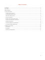
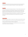
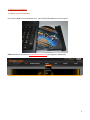
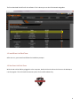
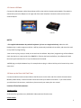
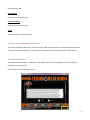
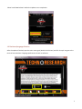
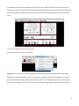
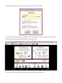
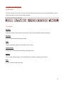
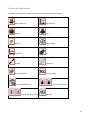
DIRECT LINK FLASH TUNER
Quick Start Guide
This Guide is intended to answer basic Direct Link tuning questions and to act as a Quick Start
Guide. It is not intended to be encyclopedic on the tuning process - only to answer basic
questions about setting up Direct Link.
Table of Contents
Introduction..................................................................................................................................................................... 2
How it Works ................................................................................................................................................................... 2
About this Manual ........................................................................................................................................................... 2
1. Setup and Installation................................................................................................................................................... 3
1.1 Where to get the Software ..................................................................................................................................... 3
1.2 Install Direct Link Flash Tuner ................................................................................................................................. 4
1.3 Run Direct Link Flash Tuner .................................................................................................................................... 4
1.5 Connect USB Cable ................................................................................................................................................. 5
1.6 Power up the Direct Link Flash Tuner...................................................................................................................... 5
1.7 Power up to Automatically Install Drivers ............................................................................................................... 6
1.8 Update the Software .............................................................................................................................................. 6
1.10 Confirm COM Port for Communication ................................................................................................................. 8
1.11 Trouble-shooting COM Port Issues...................................................................................................................... 10
2. Toolbar Icon Descriptions ........................................................................................................................................... 11
2.1 Main Menu .......................................................................................................................................................... 11
2.2 Tab Menu ............................................................................................................................................................ 11
2.3 Direct Link Toolbar Buttons .................................................................................................................................. 12
1
Introduction
The Direct Link Kit will provide the tuner with the tools and necessary data to maximize the potential of the
installed upgrades. The system is designed for Harley-Davidson® Fuel Injection equipped motorbikes.
How it Works
The ECU is basically a calculator that sends signals to the injectors. The sensors include the temperature of the
motor (Harleys head temperature sensor), outside ambient temperature and pressure (altitude), throttle
position (TPS), engine speed (RPM) and load (KPA or MAP, manifold absolute pressure). The newer models,
(2008 and later), also have a narrow band O2 sensor and actually run in ‘closed loop’ when you tell it to.
The ECU combines all data gathered by the above mentioned sensors and compares it to the ‘scribed’ maps that
have been set up at the factory and makes adjustments so that the engine works at its best given the
circumstances.
About this Manual
The Direct Link User’s Quick Start Guide is a simple overview of installing and setting up the Direct Link system.
This manual is organized by chapters to assist novice users with getting started. Many topics covered in this
manual are also covered in the help menus available in the program itself.
This Guide/Manual has been written thinking that not only professionals will use it, but also non-professionals.
That is the reason it is written in a non-technical way.
2
1. Setup and Installation
1.1 Where to get the Software
Insert the CD-ROM from TechnoResearch Inc. into the DVD/CD-ROM drive of the computer…
OR download from our website (www.technoresearch.com, go to Support > Downloads).
3
The first download link will be for the software. This is where you can also find manuals and guides.
1.2 Install Direct Link Flash Tuner
After auto-run, press install and follow the installation prompts.
1.3 Run Direct Link Flash Tuner
With the red or blue USB key plugged in to the computer, double-click on the Direct Link icon on the desktop to
run the program. This will install the necessary driver for the USB hardware key.
4
1.5 Connect USB Cable
Connect the USB computer cable (shown below at left) to the Vehicle Communication Module. The module is
shown below, with the USB port on the right side of the metal endplate. Connect the other end to the PC’s
second USB port.
VCM-TR1
VCM-TR3
NOTES:
• The supplied USB Hardware Key with this software is for use on a single vehicle only. When the USB
Hardware Key is used to program a vehicle, it will be permanently attached to that vehicle, and cannot be used
on any other for programming.
•You can use any key, empty or used, to start and use this software. Only when ‘programming’ will the software
check that the key is empty and lock it to THAT ECU. If the key has been used before, the software will check
that the key will match the ECU. If not, the software will be closed.
•NEVER plug in multiple hardware keys. For example: do not plug in a Direct Link key and a Centurion key at the
same time!
1.6 Power up the Direct Link Flash Tuner
Connect the Vehicle Communication Cable to the DB-15 port on the other end of the Vehicle Communication
Module (shown below). Connect the other end to the motorcycle’s data link connector. If you cannot locate
your bike’s data link connector, see below or please consult your motorcycle user manual.
Location of Data link connector:
Touring models:
Underneath the right side cover. (2008-2012 Underneath the left side cover)
Softail models:
5
Underneath the seat.
Dyna models:
Underneath the left side cover.
Sportster models:
Underneath the left side cover.
VRSC:
Underneath the front side neck cover.
1.7 Power up to Automatically Install Drivers
The VCM is powered by the battery of the motorcycle. Make sure the ignition is ON and the RUN switch is ON.
The light on the VCM should be lit. This will cause the software to search for and install the cable drivers.
1.8 Update the Software
After the Direct Link software is installed, run the updater to get the latest program versions including the
calibrations and the manuals.
Click ‘Updater’ in the bottom right corner:
6
Select ‘Install New Release’ and let the Updater run to completion.
1.9 Disclaimer/Language Selection
After the update is finished, open the main menu again (double-click DL Icon) and click ‘Accept’ to agree to the
terms of use and select a language preference to launch to software.
7
The software will open to the Programming screen. This screen is where you will do a lot of your work. You
should ‘play’ with this screen and practice opening and closing editing tables and connecting to the motorcycle.
Each table you edit will change something on the motorcycle and you will always program the ECU from this
screen.
1.10 Confirm COM Port for Communication
Under ‘Communication’, select ‘Port Setting’.
Important: If the Direct Link hardware (VCM) is not powered, then the correct COM Port will not appear
(indicated by an illuminated LED). To rectify, press ‘Cancel’ and power the Direct Link hardware by turning on
the ignition switch and making sure the engine stop/run switch is in the RUN position. Once the LED light is on,
the Direct Link hardware is on, select ‘Communication’ and ‘Port Setting’ again to select the correct COM Port.
8
Either select the COM Port manually using the arrows or click the box to use USB:
Click ‘OK’ and then test connection by clicking ‘ECU Info’ on the programming screen. If connection is successful,
the ECU Info section will populate with the bike’s current information:
If connection fails, see the next step for trouble-shooting COM port connection issues.
9
1.11 Trouble-shooting COM Port Issues
If the COM port cannot be selected and checking the USB box does not allow connection, it means that the
driver for it was not correctly installed when installing the software. Go to the computers Control Panel, select
‘Hardware and Sound’, select ‘Device Manager’. Expand ‘Other Devices’ or ‘COM Ports’ to locate the serial
converter or key. If the COM port is not showing, the yellow triangle icon will appear:
IMPORTANT: This means that the driver was not correctly installed when installing the Centurion U/UE/M/S
software. When you right click and select ‘Update Driver Software’, you can manually browse and point the
search at your CD/DVD drive if the software CD is in, OR search automatically and the files should be pulled.
After the correct device driver is installed or updated, the window will look like this:
Go back to the ‘Port Setting’ window in the software and make sure the corresponding number is selected—in
this case, COM14 OR check the box for USB. Test for connection again by selecting ‘ECU Info’.
10
2. Toolbar Icon Descriptions
2.1 Main Menu
The Direct Link main menu offers a variety of commands. Below the main menu are the Toolbar Buttons, which
offer quick access to the most often used commands.
2.2 Tab Menu
File Menu:
Commands to open, export, backup or save a file, close an active window, and quit the program
Edit-Table:
Access to editable tables and engine settings
View:
Contains commands related to what mode you are viewing
Communication:
Commands for connecting, disconnecting, and programming
Options:
Trace and data record settings, access to Mobile Dyno, settings to change units and colors
Help:
Displays a variety of help commands
11
2.3 Direct Link Toolbar Buttons
The toolbar buttons allow one-click access to the most frequently used commands.
Open Calibration
Open Data Log
Save As…
Print
Reflash
Gauges/Meters
Strip Chart
PVI
Connect
Disconnect
Recording ON/OFF
Channels/Mode
Auto map/Mobile Dyno
Front & Rear Spark Table
Front & Rear Fuel Table
AFR Table
12