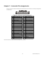
1
C
C
C
MODEL USB-CTR-15
USER MANUAL
FILE: MUSB-CTR-15.A1c
Notice
The information in th is document is provided for reference only. Portwell does not assume any liability arising out of
the applica tion or use of the inform ation or products d escribed herein. This document may contain or reference
information and prod ucts protected by copyrights or patents and does not co nve y any license unde r the paten t rights
of Portwell, nor the rights of others.
IBM PC, PC/XT, and PC/AT are registered trademarks of the International Business Machines Corporation.
Printed in US A. C opyright 20 05, 2006 by Portwell I/O P rodu cts Inc. All rights reserved.
WARNING!!
ALWAYS CONNECT AND DISCONNECT YOUR FIELD CABLING WITH THE
COMPUTER POWER OFF. ALWAYS TURN COMPUTER POW ER OFF
BEFORE INSTALLING A CARD. CONNECTING AND DISCONNECTING
CABLES, OR INSTALLING CARDS INTO A SYSTEM W ITH THE COMPUTER
OR FIELD POWER ON MAY CAUSE DAMAGE TO THE I/O CARD AND WILL
VOID ALL WARRANTIES, IMPLIED OR EXPRESSED.
2
Manual USB-CTR-15
Warranty
Prior to ship me nt, Portwell equipment is tho roughly inspected and tested to ap plica ble spe cifica tions. How ever, should
equipment failure occur, Portwell assures its customers that prompt service and support will be available. All
equipment originally manufactured by Portwell which is found to be defective w ill be repaired or replaced subject to
the following considerations.
Terms and Conditions
If a unit is suspected of failure, contact Portwell' Customer Service department. Be prepared to give the unit model
num ber, serial num ber, and a description of the failure sym ptom (s). W e m ay su gge st som e sim ple tes ts to confirm
the failure. We will assign a Return Material Authorization (RMA ) number which must appear on the outer label of the
return package. All units/components should be properly packed for handling and returned with freight prepaid to the
Portwell designated Service Center, and will be returned to the customer's/user's site freight prepaid and invoiced.
Coverage
First Three Years: Returned unit/part will be repa ired and/o r replaced at Portwell option with no charge for labor or
parts not exclud ed b y wa rranty. Wa rranty com me nce s with equ ipm ent shipm ent.
Following Years: Throughout you r equipment's lifetim e, Portwell stands ready to provide on-site or in-plant service
at reasonable rates similar to those of other manu facturers in the industry.
Equipment Not Manufactured by Portwell
Equipment provided but not manufactured by Portwell is warranted and will be repaired according to the terms and
conditions of the respective equipme nt manu facturer's warranty.
General
Under this Warranty, liability of Portwell is limited to replacing, repairing or issuing credit (at Portwell discretion) for any
prod ucts which are proved to be defective during the warranty period. In no case is Portwell liable for consequential
or special da ma ge a rriving from u se or misuse of our prod uct. The cu stomer is resp onsible for all charges caused
by modifications or additions to Portwell equipment not approved in writing by Portwell or, if in Portwell opinion the
equipment has be en sub jected to ab normal us e. "A bnorm al us e" for purposes of th is warranty is defined as any use
to wh ich th e equipment is exposed other than that use specified or intended as evidenced by purchase or sales
representation. Other than the above, no other warranty, expressed or implied, shall apply to any and all such
equipment furnished or sold by Portwell.
3
Manual USB-CTR-15
Table of Contents
Chapter 1: Introduction . . . . . . . . . . . . . . . . . . . . . . . . . . . . . . . . . . . . . . . . . . . . . . . . . . . . . 5
Specifications . . . . . . . . . . . . . . . . . . . . . . . . . . . . . . . . . . . . . . . . . . . . . . . . . . . . . . . . . . . . . . . . . . 7
Chapter 2: Installation . . . . . . . . . . . . . . . . . . . . . . . . . . . . . . . . . . . . . . . . . . . . . . . . . . . . . . 9
Hardware Installation . . . . . . . . . . . . . . . . . . . . . . . . . . . . . . . . . . . . . . . . . . . . . . . . . . . . . . . . . . . . 9
Chapter 3:
Chapter 4:
Chapter 5:
Chapter 6:
Hardware Specifications . . . . . . . . . . . . . . . . . . . . . . . . . . . . . . . . . . . . . . . . . 10
USB Address Information . . . . . . . . . . . . . . . . . . . . . . . . . . . . . . . . . . . . . . . . 13
Programming . . . . . . . . . . . . . . . . . . . . . . . . . . . . . . . . . . . . . . . . . . . . . . . . . . . 14
8254 Counter/Timer . . . . . . . . . . . . . . . . . . . . . . . . . . . . . . . . . . . . . . . . . . . . . . 16
Operational Modes . . . . . . . . . . . . . . . . . . . . . . . . . . . . . . . . . . . . . . . . . . . . . . . . . . . . . . . . . . . . . 16
Chapter 7: Connector Pin Assignments . . . . . . . . . . . . . . . . . . . . . . . . . . . . . . . . . . . . . . 18
List of Figures
Figure 1-1: Block Diagram . . . . . . . . . . . . . . . . . . . . . . . . . . . . . . . . . . . . . . . . . . . . . . . . . . . . . . . . . . . . . . . . . . . . 8
Figure 3-1: Option Selection Map . . . . . . . . . . . . . . . . . . . . . . . . . . . . . . . . . . . . . . . . . . . . . . . . . . . . . . . . . . . . . . 10
List of Tables
Tab le 7-1: 50-P in Co nne ctor P in As signme nts . . . . . . . . . . . . . . . . . . . . . . . . . . . . . . . . . . . . . . . . . . . . . . . . . . . 18
4
Manual USB-CTR-15
Chapter 1: Introduction
Features
•
Fifteen 16-bit Counter-Timers (5 x 8254)
•
Hig h-speed US B 2.0 device, US B 1.1 backw ards co mpatible
•
User Wiring Adaptor card provided for flexible yet easy counter concatenation
•
Standard Configuration Adaptor pre-configured for event counting, frequency measurem ent, pulse
•
Po we r provide d via US B cable
width measurement, or frequency generation
•
Resettable fused +5VDC output
•
Standard 50pin IDC type connector with key
•
Screw Terminal board enables quick connection of signals prior to cable harnessing
•
PC /104 size (3 .550 by 3.7 75 in.)
•
Rug ged ind ustrial enclosure
FUNCTIONAL DESCRIPTION
This USB board is an ideal solution for adding portable, easy-to-install counter-timer capabilities to any
computer w ith a US B port. The board is a U SB 2.0 high spe ed device , offering the fastest spe ed ava ilable
with the USB bus. It is fully compatible with both USB 1.1 and USB 2.0 ports. The card is plug-and-play
allow ing quick c onn ect/discon nec t whene ver yo u ne ed a ddition al I/O o n your USB port.
The board features 5 fully-undedicated industry standard 82C54 counters. The I/O wiring con nections are via
an industry standard 50-pin connector or via a terminal block adapter board. For external circuits, fused
+5VDC powe r is av ailable at the co nnector. The resettable fuse is rated at 0.5A . In addition to + 5V p owe r,
a 10MH z output signal provides a reliable timebase for many applications.
The board is designed to be used in rugged industrial environme nts but is sm all eno ugh to fit nicely o nto any
desk or testing station. The card is PC/104 size - including the proper mounting holes - and ships inside a
steel pow der-c oate d en closu re with an a nti-skid bottom.
MODEL OPTIONS
Options:
-P
-OEM
-E
external power and AC/DC adapter
board only version (no enclosure)
no screw term inal acce ssory
Included with your board
The following components are included with your shipment. Please take the time now to ensure that no
items are damaged or missing.
1.
USB-CTR -15 (installed in enclosure, if not -OEM Option)
2.
Screw Terminal Accessory (not included with the -E Option)
3.
Software Master CD
4.
USB I/O Quick-Start Guide
5.
6 foot USB cable
6.
User Wiring Adaptor
5
Manual USB-CTR-15
7.
Standard Configuration Adaptor
Optional Accessories
The following accessories are provided for the -P Option
1.
9V AC /DC Powe r Su pply
6
Manual USB-CTR-15
Specifications
Counter/Timers
•
Type:
82C 54-10 program ma ble interval counters
•
Ou tput D rive:
2.0 VDC min., source 32 mA
•
Max imum Input Frequency:
0.55 VDC max., sink 64 mA
10MHz
•
Input Gate:
TTL/CM OS com patible (10k S Pull-up)
•
Clock:
On-board, 10 MHz crystal-controlled clock
•
Active Count Edge:
Negative edge (10k S Pull-up)
•
Minimum Clock Pulse Width:
(input characteristic) 30 ns high, 40 ns low
•
Minim um Divisor:
divide-by-2
•
Ma ximu m D ivisor:
divide-by-6 5536 (16-bits, load va lue “0")
•
Timer Range:
16 b its
Bus Type
•
USB 2.0 high-speed (480 Mb/s)
•
circa 4000 transactions per second
Power
•
Basic unit: 60mA typical (no load); 12mA with max counter transitions
•
+5 VDC from the USB bus or external power supply depending on user configuration. The USB
bus is specified to provide 500 mA to most desktop environments. This gives you 440 mA
available (500mA -60mA = 440mA ). If using more than a total of 500mA, use optional 9 VDC (on
board voltage regulator outputs +5 VDC to card) external power supply and remove VUSB jumper
and place jum per on VE XT . Then plug in ex ternal po we r before plug ging into U SB port . This
option will give you a total of 1000mA available.
•
+5V resettable fu se at 0.5A locate d on connec tor.
Environmental
•
Operating Temperature Range: 0 °C. to 70 °C.
•
Storage Temperature Range:
-40 °C. to +85 °C.
•
Hum idity:
0 to 90% RH, non-condensing.
•
Board Dimension:
3.550 x 3.775 inches.
•
Box Dimension:
4.00 x 4.00" x 1.25 inches.
7
Manual USB-CTR-15
Figure 1-1: Block Diagram
Note: Gate and Clock inputs are pulled up through 10k S resistors.
8
Manual USB-CTR-15
Chapter 2: Installation
Software CD Installation
These paragraphs are intended to detail the software installation steps as we ll as describe what is being
installed.
The software provided with this board is contained on one CD and m ust be installed onto your hard disk prior
to use. To do this, perform the following steps as appropriate for your software format and operating system.
Substitute the app ropriate drive letter for your CD-ROM or disk drive where you see d: in the examples
below.
WIN95/98/Me/NT/2000/XP/2003
a.
b.
Place the CD into your CD-ROM drive.
The CD sho uld autom atically ru n the ins tall program . If the in stall program does not click START |
c.
RUN and type d:install, click OK or press K .
Follow the on-screen prompts to install the software for this board.
1.
Please refer to linux.htm on the CD -ROM for information on installing under linux.
LINUX
Hardware Installation
The boa rd can be installed in an y US B 2.0 or U SB 1.1 port.
Please install the software package before plugging the hardware into the system.
9
Manual USB-CTR-15
Chapter 3: Hardware Specifications
Option Selections
Refer to the setup programs on the CD provided with the board. Also, refer to the Block Diagram and the
Op tion Selection Map wh en reading this se ction of the manual.
Figure 3-1: Option Selection Map
10
Manual USB-CTR-15
USB CONNECTOR
The USB connector is a Type B USB connector and mates with the cable provided. The USB port provides
communication signals along with +5 VDC power. The board can be powered from the USB port or, if needed for
higher current applications, an external power supply can be used.
LED
The LED on the front of the enclosure is used to indicate power and data transmissions. When the LED is in an
illuminated steady green state, this signifies that the board is successfully connected to the computer and has
been detected and configured by the operating system. When the LED flashes continuously, this signifies that
there is data being transmitted over the USB bus.
DC POWER JACK (OPTIONAL)
Pleas e note, no t all boards w ill contain this option. Th is is an option for high current application s wh en m ore
current is needed than what your computer can provide on the USB port (typically 500 mA). The DC jack has a
2.00 mm post on board and is des igned to be used w ith the 9 VD C A C/D C external powe r supply tha t ships with
this op tion. Th e voltage regu lator on boa rd reg ulates the 9 VD C and p rovides 5 VD C to the onbo ard circuitry.
When using external power, switch the jumper located near the USB connector to VEXT, otherwise when the
jump er is in the VU SB position cu rrent is draw n from the US B po rt (please co nsult the op tion selection map for a
visual referen ce).
50 PIN BOX HEADER
The 50 pin box heade r has standard .100" spa cing betw een pins a nd is k eyed to preve nt improp er conne ctions . It
can be used with standard IDC type ribbon cables or the screw terminal board that plugs directly into the box
head er.
As shown in the Option Selection drawing, this board contains two 50-pin connectors P2 and P3.
The right-angle connector, called "P2", is designed to connect to your field cabling. This connector fits through the
aperture in the standard enclosure, and is therefore available cleanly from outside the steel enclosure.
The other 50-pin header, called "P3", has an identical pinout, but is not designed for cables. Rather, it is intended
that P 3 will be used to interco nne ct the v arious onboa rd counte rs.
USER CONFIGURATION ADAPTOR
To a ssist yo u in w iring the counters together a sm all PC B is provided, called th e "U ser C onfiguration Adap tor".
This Adaptor is for you to wire the counter arrangement you need. As shown in the following drawing, two
through-hole 0.1" spacing sold er pads are provided for each sign al from each cou nter, along with a m ating 50-pin
head er.
By connecting wires between holes you can
create a permanent wiring adaptor "plug"
that installs into P3, and creates the counter
wiring sch em e yo ur applicatio n needs. This
User Configuration Adaptor eliminates the
need for complex wiring harnesses at P2,
and increases the reliability of your system.
11
Manual USB-CTR-15
DEFAULT CONFIGURATION ADAPTOR
In addition to the User Configuration Adaptor, a pre-wired "Default Configuration
Adaptor" is also provided. This small PCB does not include room for user wiring
connections; instead, it comes pre-wired into a very efficient counter scheme,
wherein each 8254 (three counters) is configured for
common counter-timer tasks. The drawing to the
right sho ws the bloc k dia gram for this Default
Con figuration Ad aptor.
Much of the software provided assumes this default configuration
adaptor has been installed at P3.
12
Manual USB-CTR-15
Chapter 4: USB Address Information
Use the provided driver to access the USB board. This driver will allow you to determine how many supported
US B de vices are currently installed, an d eac h dev ice’s type. This information is returned as a V endo r ID (VID ),
Product ID (PID) and Device Index.
The boa rd’s V ID is “0x16 05", a nd its P ID is “0x80 20".
The Device Index is determined by how many of the device you have in your system, and provides a unique
identifier allowin g yo u to acc ess a s pecific board at will.
13
Manual USB-CTR-15
Chapter 5: Programming
This boa rd contains Five 82 54 chips. Eac h 82 54 conta ins 3 1 6-bit co unte r/timers and a single c ontro l register.
This effectively provides 15 individual 16-bit down-counter/timers, but only 5 control registers. Because of this, the
counters are referenced by two methods: 8254 number + counter index, or counter number. In the software you
will norm ally use 82 54 nu mb er+co unter inde x, but its usua lly more co nven ient to use c ounter num ber for hard ware
and wiring considerations. The following table shows the mapping between these two num ber schemes.
8254 number
0
0
0
1
1
1
2
2
2
3
3
3
4
4
4
counter index
0
1
2
0
1
2
0
1
2
0
1
2
0
1
2
counter number
0
1
2
3
4
5
6
7
8
9
10
11
12
13
14
Pins
1-3
4-6
7-9
10 -12
13 - 15
16 - 18
19 - 21
22 - 24
25 - 27
28 - 30
31 - 33
34 - 36
37 - 39
40 - 42
43 - 45
The driver software provided with the board uses a 32-bit .dll front end compatible with any Windows programming
language. Samples provided in Borland C++ Builder, Borland Delphi, Microsoft Visual Basic, and Microsoft Visual
C+ + dem onstrate the use of the driver.
The following functions are provided by the driver in Windows.
These functions will allow you to operate the counter-timer functionality and board-level functions.
For detailed inform ation on each function refer to the .html Driv er M anual loca ted in the Win32 directory for this
board.
unsigned long GetDevices(void )
unsigned long QueryDeviceInfo(DeviceIndex, pPID, pNam e, pDIOBytes, pCounters)
unsigned long DIO_Configure(DeviceIndex, bTristate, pOutMask, pData)
unsigned long CTR_8254Mode(DeviceIndex, BlockIndex, CounterIndex, Mode)
unsigned long CTR_8254ModeLoad(DeviceIndex, BlockIndex, CounterIndex,Mode, LoadValue)
unsigned long CTR_8254ReadModeLoad(DeviceIndex, BlockIndex, CounterIndex, Mode, LoadValue ,
pReadValue)
unsigned long CTR_8254Read(DeviceIndex, BlockIndex, CounterIndex, pReadValue)
unsigned long CTR_StartOutputFreq(DeviceIndex, CounterIndex, pHz)
—P lease note, CTR_StartOutputFreq assumes the “Standard Configuration Adaptor” is installed, and may
therefore not be useful in your application.
14
Manual USB-CTR-15
Low Level Reference:
Please note, this information is very low-level, and is generally only of use when writing code for
operating s ystems for w hich w e do not yet provid e a h igh-le vel driver. Feel free to skip the re st of th is
chapter if it doesn’t apply to your application.
In addition to the Windows driver provided above, the USB bus provides a lower-level alternative method of
interfacing with the board.
US B defines sev eral stan dard operations, one of wh ich (“Ve ndor R equest”) is use d by this board to co ntrol all
Counter related functionality. Each USB vend or request has two word-size parameters, Value and Index, plus a
lengthed data buffer that can be written to the board or read from the board. The following Vendor Request Codes
are used by this board:
Vendor Request 20h: Counter Read
This req uest rea ds the current value in the specified cou nter.
Value: The low byte is the index of the 8254, from 00h to 04h. The high byte is the index of the counter, from 00h
to 02h. Note that the high byte is not a mode control byte.
Index: Reserved, use 0000h.
Data Read: 2 bytes, the current value in the counter.
Vendor Request 21h: Counter Mode
This request puts a counter in the specified mode, but does not load a load value. This can be useful for setting
the outpu t value of the c oun ter, without actually ma king it coun t. (Mode 0 sets th e ou tput low , mo de 1 sets it high.)
Value: The low byte is the inde x of th e 8254, from 00h to 04h. The high byte is the mode co ntrol byte (see table
abov e).
Index: Reserved, use 0000h.
Data : None.
Vendor Request 22h: Counter Load
Value: The low b yte is the index of the 825 4, from 00h to 04h. Th e high byte is a m ode control byte, but on ly bit 7
and 6 are significant - this function will ignore the other bits).
Index: The load value, from 0 to 65535
Data Read: None.
Vendor Request 23h: Counter Mode/Load or Read/Mode/Load
This request puts a counter in the specified mode, then loads it with the specified load value. It can optionally read
the current value in the counter before moding it. See the chapter on the 8254 counter/timer for details on the
various m ode s; the b its sho wn in the table below as “1" nee d to rema in set.
Value: The low byte is the inde x of th e 8254, from 00h to 04h. The high byte is the mode co ntrol byte (see table
below ).
Index: The load value, from 0 to 65535
Data Read: Either none, or 2 bytes. If 2 bytes are read as part of the request, they will be set to the current value
of the counter before the mode.
Bit
Content
7
6
Counter Index,
0-2
Tab le: Co unte r Mo de C ontro l Byte
5
4
3
1
1
15
2
Counter Mode,
0-5
1
0
0
Manual USB-CTR-15
Chapter 6: 8254 Counter/Timer
This board contains five 82C54 counter(s) that each include three 16-bit cou nter/timers. The default
configuration adaptor comes configured in an optimal modu le for us e as event counte rs, frequ enc y output,
pulse width, and frequency measurement (See Block Diagram). Each counter can be programmed to any
count as low as 1 or 2, and up to 65,536 , depen ding on the m ode c hose n. For thos e interested in more
detailed informa tion, a full description ca n be fou nd in the Intel (or equivalen t man ufacturer's) data sheet,
prov ided in the /chipdocs directo ry on the S oftware M aster CD .
Refer to Chapter 5: Programming, and the .html Driver Manual document installed by the Software Master CD
for inform ation on using the installed software driver for this board. The following data is provided only for
reference, as it is unlikely to be needed when using the provided driver. Please note the block diagram
description of how the 9 pins associated with 8254 counters are configured into an optimum counter-timer
module on this board.
In addition, the driver and firmware on the board requires a fu ll 16-b it load opera tion; do not se lect “low -byte
only” o r “high-byte only” m ode s for the counters.
Additional low-level information on the 82C54 can be found on the Software Master C D in the /chipdocs
directory.
Operational Modes
The 8254 modes of operation are described in the following pa ragra phs to fam iliarize you with the versa tility
and pow er of this device . For those interested in m ore detailed informa tion, a full description of the 8254
programmable interva l timer can be found in the Intel (or equivalent manufacturers') data sheets. The
follow ing co nve ntions apply for use in d escribing o pera tion of the 82 54 :
Clock:
Trigger:
Counter Loading:
A positive pulse into the counter's clock input
A rising edge input to the counter's gate input
Programming a binary count into the counter
Mode 0: Pulse on Terminal Count
After the cou nter is loa ded, the output is s et low a nd will re main low until the counter decrements to zero. The
output then go es high and rem ains high until a new coun t is loaded into the coun ter. A trigger enables the
cou nter to start de crem enting.
Mode 1: Retriggerable One-Shot
The output go es low on the clock pulse following a trigger to begin the one-shot pulse and goes high when
the cou nter reaches zero. Additional triggers result in reloading the co unt and starting th e cyc le ove r. If a
trigger occurs before the counter decrements to zero, a new count is loaded. This forms a retrig gerable
one-shot. In mode 1, a low output pulse is provided with a period equal to the counter count-down time.
Mode 2: Rate Generator
This mode provides a divide-by-N capability where N is the count loaded into the counter. When triggered,
the counter output goes low for one clock period after N counts, reloads the initial cou nt, and the cycle starts
over. This mode is periodic, the same sequence is repeated indefinitely until the gate input is brought low.
This mode also works well as an alternative to mode 0 for event counting.
16
Manual USB-CTR-15
Mode 3: Square Wave Generator
This mode operates like mode 2. The output is h igh for half of the count and low for the other half. If the count
is even, then the output is a symmetrical square wave. If the count is odd, then the output is high for (N +1)/2
cou nts and low for (N-1)/2 counts. Periodic triggering or frequency synthesis are two possible applications
for this mode. Note that in this mode, to achieve the square wave, the counter decrements by two for the total
loaded coun t, then re loads and de crem ents by tw o for the second part of the w ave form .
Mode 4: Software Triggered Strobe
This mode se ts the output high and, w hen the co unt is loaded, the counte r beg ins to coun t dow n. When the
counter reaches zero, the output will go low for one input period. The counter must be reloaded to repeat the
cycle. A low gate inpu t will inhibit the counter.
Mode 5: Hardware Triggered Strobe
In this mode, the co unter w ill start counting after the rising edge of the trigger input and will go low for one
clock period when the terminal count is reached. The counter is retriggerable. The output will not go low until
the full count after the rising edg e of the trigger.
17
Manual USB-CTR-15
Chapter 7: Connector Pin Assignments
A 50-pin connector provided on the back plate o f these boa rds for I/O co nne ctions . Conne ctor pin ass ignm ents
are listed be low.
Table 7-1: 50-Pin Connector Pin Assignments
Pin
1
3
5
7
9
11
13
15
17
19
21
23
25
27
29
31
33
35
37
39
41
43
45
47
49
Function
Tim er 0 C lock In put*
Timer 0 Output
Tim er 1 G ate Input*
Tim er 2 C lock In put*
Timer 2 Output
Tim er 3 G ate Input*
Tim er 4 C lock In put*
Timer 4 Output
Tim er 5 G ate Input*
Tim er 6 C lock In put*
Timer 6 Output
Tim er 7 G ate Input*
Tim er 8 C lock In put*
Timer 8 Output
Tim er 9 G ate Input*
Tim er 10 Cloc k Input*
Timer 10 Output
Tim er 11 Ga te Input*
Tim er 12 Cloc k Input*
Timer 12 Output
Tim er 13 Ga te Input*
Tim er 14 Cloc k Input*
Timer 14 Output
Output From Inverter
+5V DC, 0.5A Fused
Pin
2
4
6
8
10
12
14
16
18
20
22
24
26
28
30
32
34
36
38
40
42
44
46
48
50
Function
Tim er 0 G ate Input*
Tim er 1 C lock In put*
Timer 1 Output
Tim er 2 G ate Input*
Tim er 3 C lock In put*
Timer 3 Output
Tim er 4 G ate Input*
Tim er 5 C lock In put*
Timer 5 Output
Tim er 6 G ate Input*
Tim er 7 C lock In put*
Timer 7 Output
Tim er 8 G ate Input*
Tim er 9 C lock In put*
Timer 9 Output
Tim er 10 Ga te Input*
Tim er 11 Cloc k Input*
Timer 11 Output
Tim er 12 Ga te Input*
Tim er 13 Cloc k Input*
Timer 13 Output
Tim er 14 Ga te Input*
Input To Inverter
Ground
10MHz Signal Output
*Note: Gate and Clock inputs are pulled up through 10k S resistors.
18
Manual USB-CTR-15
Customer Comments
If you expe rience an y problem s with this m anu al or just want to give us som e feedba ck, ple ase em ail us at:
[email protected]. Please detail any errors you find and include your mailing address so that we can send
you any manual updates.
19
Manual USB-CTR-15