1
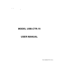
10623 Roselle Street, San Diego, CA 92121 y (858) 550-9559 y Fax (858) 550-7322
[email protected] y www.accesio.com
USB 16-CHANNEL ANALOG INPUT
MODULE
MODEL USB-AI12-16x
USER MANUAL
File: MUSB-AI12-16x.B1a
Notice
The information in this document is provided for reference only. ACCES does not assume any liability arising
out of the application or use of the information or products described herein. This document may contain or
reference information and products protected by copyrights or patents and does not convey any license
under the patent rights of ACCES, nor the rights of others.
IBM PC, PC/XT, and PC/AT are registered trademarks of the International Business Machines Corporation.
Printed in USA. Copyright 2008 by ACCES I/O Products, Inc. 10623 Roselle Street, San Diego, CA 92121.
All rights reserved.
WARNING!!
ALWAYS CONNECT AND DISCONNECT YOUR FIELD CABLING WITH
THE COMPUTER POWER OFF. ALWAYS TURN COMPUTER POWER OFF
BEFORE INSTALLING A BOARD. CONNECTING AND DISCONNECTING
CABLES, OR INSTALLING BOARDS INTO A SYSTEM WITH THE
COMPUTER OR FIELD POWER ON MAY CAUSE DAMAGE TO THE I/O
BOARD AND WILL VOID ALL WARRANTIES, IMPLIED OR EXPRESSED.
2
Manual USB-AI12-16x
Warranty
Prior to shipment, ACCES equipment is thoroughly inspected and tested to applicable specifications.
However, should equipment failure occur, ACCES assures its customers that prompt service and support will
be available. All equipment originally manufactured by ACCES which is found to be defective will be repaired
or replaced subject to the following considerations.
Terms and Conditions
If a unit is suspected of failure, contact ACCES' Customer Service department. Be prepared to give the unit
model number, serial number, and a description of the failure symptom(s). We may suggest some simple
tests to confirm the failure. We will assign a Return Material Authorization (RMA) number which must appear
on the outer label of the return package. All units/components should be properly packed for handling and
returned with freight prepaid to the ACCES designated Service Center, and will be returned to the
customer's/user's site freight prepaid and invoiced.
Coverage
First Three Years: Returned unit/part will be repaired and/or replaced at ACCES option with no charge for
labor or parts not excluded by warranty. Warranty commences with equipment shipment.
Following Years: Throughout your equipment's lifetime, ACCES stands ready to provide on-site or in-plant
service at reasonable rates similar to those of other manufacturers in the industry.
Equipment Not Manufactured by ACCES
Equipment provided but not manufactured by ACCES is warranted and will be repaired according to the
terms and conditions of the respective equipment manufacturer's warranty.
General
Under this Warranty, liability of ACCES is limited to replacing, repairing or issuing credit (at ACCES
discretion) for any products which are proved to be defective during the warranty period. In no case is
ACCES liable for consequential or special damage arriving from use or misuse of our product. The customer
is responsible for all charges caused by modifications or additions to ACCES equipment not approved in
writing by ACCES or, if in ACCES opinion the equipment has been subjected to abnormal use. "Abnormal
use" for purposes of this warranty is defined as any use to which the equipment is exposed other than that
use specified or intended as evidenced by purchase or sales representation. Other than the above, no other
warranty, expressed or implied, shall apply to any and all such equipment furnished or sold by ACCES.
3
Manual USB-AI12-16x
TABLE OF CONTENTS
Chapter 1: Introduction..................................................................................................................................... 5
Features .......................................................................................................................................................... 5
Applications.................................................................................................................................................... 5
Functional Description .................................................................................................................................. 5
Figure 1-1: Block Diagram........................................................................................................................... 6
Analog Inputs.............................................................................................................................................. 7
A/D Start ...................................................................................................................................................... 7
Oversample ................................................................................................................................................. 8
Calibration................................................................................................................................................... 8
Figure 1-2: System Calibration Utility screenshot 1 (setup)........................................................................ 9
Figure 1-3: System Calibration Utility screenshot 2 (range select) ............................................................. 9
Figure 1-4: System Calibration Utility screenshot 3 (offset)...................................................................... 10
Figure 1-5: System Calibration Utility screenshot 4 (gain) ........................................................................ 10
Figure 1-6: System Calibration Utility screenshot 5 (confirmation) ........................................................... 11
Figure 1-7: System Calibration Utility screenshot 6 (finish and save)....................................................... 11
Digital I/O................................................................................................................................................... 11
Counter/Timer ........................................................................................................................................... 11
Ordering Guide............................................................................................................................................. 12
12-Bit Models ............................................................................................................................................ 12
16-Bit Models ............................................................................................................................................ 12
Model Options .............................................................................................................................................. 12
Included with your board ............................................................................................................................ 12
Optional accessories................................................................................................................................... 12
Chapter 2: Installation..................................................................................................................................... 13
Software CD Installation.............................................................................................................................. 13
Hardware Installation................................................................................................................................... 13
Chapter 3: Hardware Details........................................................................................................................... 14
Option Selection........................................................................................................................................... 14
Figure 3-1: Option Selection Map.............................................................................................................. 14
USB Connector (P1)..................................................................................................................................... 15
Embedded USB Connector (P4) ................................................................................................................. 15
LED ................................................................................................................................................................ 15
DC Power Jack (Optional) ........................................................................................................................... 15
68-PIN I/O CONNECTOR (J1) ...................................................................................................................... 15
Chapter 4: USB Address Information ............................................................................................................ 16
Chapter 5: Programming ................................................................................................................................ 17
Sample Programs......................................................................................................................................... 17
Figure 5-1: DIO Sample screenshot 1....................................................................................................... 17
Figure 5-2: DIO Sample screenshot 2....................................................................................................... 18
Figure 5-3: Analog Input Sample screenshot............................................................................................ 18
Chapter 6: Connector Pin Assignments ....................................................................................................... 19
Chapter 7 Specifications................................................................................................................................. 20
Analog Inputs ............................................................................................................................................... 20
Digital I/O ...................................................................................................................................................... 20
Counter/Timer............................................................................................................................................... 21
Environmental .............................................................................................................................................. 21
Appendix A: Counter/Timer........................................................................................................................... 22
Operational Modes....................................................................................................................................... 22
Customer Comments ...................................................................................................................................... 24
4
Manual USB-AI12-16x
Chapter 1: Introduction
This USB based Data Acquisition Module is an ideal solution for adding portable, easy-to-install
high-speed analog input and digital I/O capabilities to any computer with a USB port. The unit is a
USB 2.0 high-speed device and requires a USB 2.0 port to function.
Features
z
z
z
z
z
z
z
z
z
z
z
z
z
z
z
z
High-speed USB 2.0 device
12-bit resolution
Sampling rate
USB-AI12-16A
500Ksamples/sec (maximum aggregate)
USB-AI12-16
250Ksamples/sec (maximum aggregate)
USB-AI12-16E
100Ksamples/sec (maximum aggregate)
16 single-ended or 8 differential analog inputs (software selectable)
System Calibration Program provided to calibrate entire system
Calibration Hardware
USB-AI12-16A
Calibrated real-time output for offset/gain errors
USB-AI12-16
NONE
USB-AI12-16E
NONE
Ranges of 0-1V, 0-2V, 0-5V, 0-10V, ±1V, ±2V, ±5V, ±10V (software selectable per channel)
A/D Start sources: Software, Timer, and External Trigger (rising or falling edge; software
selectable)
A/D Modes: Single Channel or Scan
Noise reduction with Channel Oversampling
Over-voltage protection of -40V to +55V
16 high-current Digital I/O lines
16-bit programmable counter/timer
PC/104 module size and mounting compatibility
Small (4" x 4" x 1.25") rugged industrial enclosure
Miniature USB connector for embedded applications
Applications
z
z
z
z
Equipment monitoring
Environmental measurements
Embedded data acquisition
Education/Laboratory
Functional Description
This product is a USB-based Analog to Digital converter board with 16 single-ended or 8
differential analog inputs. Inputs can either be voltages or optionally 4-20mA. The board is
capable of sampling speeds up to 500K, 250K or 100K samples/sec (depending on model).
Sampling can be enabled/disabled via an I/O connector pin by an external signal. Analog input
channels are enabled as a consecutive set by software. Each channel within the set is
independently configured by software to accept one of eight different analog input ranges.
Analog to digital conversion starts or “A/D starts” are issued one of three ways: Software Start,
Timer Start, or External Trigger Start. A/D starts are software configured to be either rising or
falling edge. Additionally, A/D starts are software configured to be Single Channel or Scan. Single
Channel samples data once from the next consecutive channel within the enabled set. A Scan
samples data from all channels within the set at the fastest possible rate. To minimize noise, the
board implements a technique called Oversampling. High accuracy is achieved with a real-time
5
Manual USB-AI12-16x
internal calibration system (or software calibration, depending on model) which allows the card to
adjust for offset/gain errors at runtime, giving a more precise reading.
Also provided are 16 Digital I/O lines in 2 groups of 8 lines. Both Digital I/O bytes are individually
software selectable as input or output.
A fully programmable 8254 16-bit counter is provided with a maximum input frequency of 10MHz.
The clock, gate (inputs) and output can be accessed externally for extended functionality.
The complete unit is designed for use in rugged industrial environments but is compact enough to
fit nicely onto any desk or testing station. The board is PC/104 sized (3.550 by 3.775 inches) with
mounting capability and ships standard inside a steel powder-coated enclosure with an anti-skid
bottom.
Figure 1-1: Block Diagram
6
Manual USB-AI12-16x
Analog Inputs
There are a total of 16 single-ended or 8 differential analog inputs on this board. A consecutive
set of channels are enabled/disabled by software. This set of channels is constructed by a start
and end channel. Sampling begins on the start channel and continues through every successive
channel until the end channel is sampled. Once the end channel has been sampled, the process
repeats again from the start channel. If only one channel is being sampled, the start and end
channels would be the same. Each channel within the set is individually software configured as
either single-ended or differential. This board allows a mix of both single-ended and differential
inputs. One must note, however, that a differential signal requires a pair of channels. Thus,
when channel 0 is programmed as a differential input, both channels 0 and 8 are used and not
available as singled-ended inputs. Refer to the connector pin assignment chapter for singleended and differential pair inputs.
Optionally, resistors can be factory installed on selected channels to allow for 4-20mA or 1050mA analog inputs. Again, a mix of single-ended and differential inputs are possible but they
are factory configured as static (hardware dependent) and cannot be changed by software.
8 input ranges, 4 bipolar and 4 unipolar, are selectable by software for each individual channel.
This channel-by-channel flexibility allows for up to 8 different input ranges being acquired on a
single board. The unipolar ranges are 0-1V, 0-2V, 0-5V, and 0-10V. The bipolar ranges are ±1,
±2V, ±5V, and ±10V.
Each channel input has a slight positive bias to facilitate measurement of signals close to analog
ground (no signal information is lost due to negative offset of the ADC).
Each channel input has an over-voltage protection of -40V to +55V.
A/D Start
This board offers three software selectable sources for A/D Start: Software Start, Timer Start,
and External Start Trigger. Software Start generates an A/D Start every time the software
command is issued. The maximum frequency for a Software Start is roughly 4KHz. Timer Start
uses the on-board timer to generate an A/D Start. Frequencies ranging from 2.33 * 10-3Hz to
500KHz are possible with Timer Start. External Start Trigger uses the External Trigger pin on the
connector to generate an A/D Start. Frequencies up to 500KHz are allowed for External Start
Trigger.
A/D Start is also software configured as rising or falling edge. Furthermore, it can be disabled by
driving the A/D Start Enable pin on the connector low. By default, this signal is pulled high and
A/D Start is enabled. If A/D Start Enable goes low during a conversion, the current channel (plus
any oversampling; refer to the Oversample section) will complete all its conversions before A/D
Start is disabled. Once A/D Start Enable returns high, conversions will begin on the next
successive channel within the enabled set upon the following A/D Start.
An A/D Start can be one of two software selectable types for this board: Single Channel or
Scan. A/D Starts that are Single Channel sample one channel within the enabled set per A/D
Start. This allows for total control over the time skew between channels.
Scan, on the other hand, will sample all the channels within the enabled set per A/D Start.
Channels are sampled at 500KHz, 250KHz, or 100KHz (depending on model) to minimize the
time skew between channels.
7
Manual USB-AI12-16x
Oversample
Oversampling is a technique which continuously samples a channel multiple times at the
maximum A/D speed of your particular model. Quickly taking several samples from the same
channel allows the signal to be averaged. Averaging a signal can greatly reduce the noise
injected by both the signal and the board/system.
The oversample range is from 0 to 255 (software selectable) and applies to every channel within
the enabled set. A channel is always sampled once plus the number of oversamples that was
configured. Therefore an oversample of 0 will sample a channel once (initial sample plus 0
oversamples), oversample of 1 will sample a channel twice (initial sample plus 1 oversample), up
to an oversample of 255 which will sample a channel 256 times (initial sample plus 255
oversamples).
Each channel's oversamples are taken before sampling begins on the next consecutive channel
within the enabled set.
Calibration
All ADC's suffer from offset and gain errors. To account for this, the board implements calibration
methods to adjust for the offset/gain errors. This is particularly helpful as aging occurs and/or
operating temperature changes.
There are two methods available to calibrate: Board Calibration and System Calibration. Board
Calibration uses two on-board known reference voltages that are accessible by software. The
first reference voltage measures analog ground while the second reference voltage measures
slightly below 10V (refer to the specification for exact values). The results of sampling both
reference voltages can then be used to compare against the known values specified for each
reference. Differences between the sampled value and the known value provides offset/gain error
information for correcting these errors in hardware.
System Calibration uses the System Calibration program provided with the board. The System
Calibration program is methodically the same as Board Calibration except that the reference
voltages are supplied by the user on analog input channel 0. The advantage of System
Calibration over Board Calibration is the ability to calibrate out offset, gain, and other errors for the
entire system. The system can include such devices as sensors, signals conditioners, etc. These
components contribute to errors in the system. Calibrating using the System Calibration program
accounts for the gain/offset errors of the board AND the errors from the system it is connected to.
Only “A” models contain hardware to calibrate the output of the ADC. This hardware can be
used by both Board Calibration and System Calibration. Either method creates a file containing
offset, gain, and other errors (refer to the software reference manual for the file format). This
calibrated information within the file is then loaded onto the board and used by calibration
hardware. At this point, the ADC output is real-time with respect to the last time either Board or
System Calibration was run.
There also exists a function in software that, when called, will automatically run Board Calibration
and store the calibrated information onto the board.
For optimum calibrated data, calibration should be repeated anytime the temperature or
environment changes. Board Calibration can be performed in milliseconds and is recommended
to be performed periodically.
8
Manual USB-AI12-16x
Figure 1-2: System Calibration Utility screenshot 1 (setup)
Figure 1-3: System Calibration Utility screenshot 2 (range select)
9
Manual USB-AI12-16x
Figure 1-4: System Calibration Utility screenshot 3 (offset)
Figure 1-5: System Calibration Utility screenshot 4 (gain)
10
Manual USB-AI12-16x
Figure 1-6: System Calibration Utility screenshot 5 (confirmation)
Figure 1-7: System Calibration Utility screenshot 6 (finish and save)
Digital I/O
There are 16 Digital I/O lines (DIO0 to DIO15) available on this board. Both the low byte
(DIO0-DIO7) and high byte (DIO8-DIO15) can be individually software configured as inputs or
outputs. Each DIO line is buffered and capable of sourcing 32mA or sinking 64mA. Be sure
to consult the Power section for total power limitations before operation. By default the DIO
lines are pulled up with a 10KΩ resistor to 5V. DIO lines can also be factory configured as
pulled down.
Counter/Timer
A fully programmable 8254 16-bit counter is provided with the Counter Gate, Counter Clock,
and Counter Output signals brought out to the connector. All three signals are buffered and
capable of sourcing 32mA or sinking 64mA. Be sure to consult the Power section for total
11
Manual USB-AI12-16x
power limitations before operation. The Counter Gate, Counter Clock, and Counter Output
are pulled up with a 10KΩ resistor to 5V.
The clock input is software selectable between an internal 10MHz clock and the external
Counter Clock. The maximum allowed frequency for the clock is 10MHz.
The highly versatile 8254 contains three independent counter/timers. Counter 0 is available for
general purpose use as described above. Counters 1 and 2 are dedicated for use in timing A/D
starts.
Ordering Guide
This manual primarily describes the 12-Bit versions of this family. 16-Bit models are described in
their own manual, however, they are listed here for your reference.
12-Bit Models
•
•
•
USB-AI12-16A - Full feature version, 12-Bit 500kHz A/D, with real-time-calibration
USB-AI12-16 - Standard version, 12-Bit 250kHz, with software calibration
USB-AI12-16E – Economy version, 12-Bit 100kHz, with software calibration
16-Bit Models
•
•
USB-AI16-16A - Full feature version, 16-Bit 500kHz, with real-time-calibration
USB-AI16-16E - Economy version, 16-Bit 250kHz, with software calibration
Model Options
•
•
•
•
•
-P
-OEM
-DIN
-T
-S0x
External AC/DC adapter (power jack/regulator installed)
Board only (no enclosure)
DIN rail mounting provision
Extended Temperature Operation (-40° to +85°C)
“x” = special number designator (contact factory)
4-20mA or 10-50mA inputs
16 current inputs when factory configured as single-ended
8 current inputs when factory configured as differential
DIO lines can be configured with pull down resistors
Included with your board
The following components are included with your shipment. Please take time now to ensure
that no items are damaged or missing.
1.
2.
3.
4.
USB-AI12-16x (unit installed in labeled enclosure)
6’ USB cable
Software Master CD (PDF user manual installed with product package)
Printed USB I/O Quick-Start Guide
Optional accessories
•
•
•
C68PS18L - 68-Pin SCSI 18” shielded cable with one-touch latches
STB-68 - Screw Terminal Board (mounted on standoffs)
CUSB-MINI – 6’ USB Cable with type A connector and mini “OTG” connector for
embedded applications (mates with P4 on the board)
12
Manual USB-AI12-16x
Chapter 2: Installation
Software CD Installation
The software provided with this board is contained on one CD and must be installed onto
your hard disk prior to use. To do this, perform the following steps as appropriate for your
operating system. Substitute the appropriate drive letter for your drive where you see D: in
the examples below.
WIN98/Me/2000/XP/2003
a.
b.
c.
Place the CD into your CD-ROM drive.
The CD should automatically run the install program. If the install program does
not run, click START | RUN and type BGLQR?JJ, click OK or press -.
Follow the on-screen prompts to install the software for this board.
LINUX
a.
Please refer to linux.htm on the CD-ROM for information on installing under linux.
Hardware Installation
Please install the software package before plugging the hardware into the system.
The board can be installed in any USB 2.0 port. Please refer to the USB I/O Quick Start
Guide which can be found on the CD, for specific, quick steps to complete the hardware
and software installation.
13
Manual USB-AI12-16x
Chapter 3: Hardware Details
Option Selection
You may also refer to the setup program installed from the CD provided with the board. The only
user selectable hardware option available is VUSB vs. VEXT which selects between USB powered
or Externally powered.
Figure 3-1: Option Selection Map
14
Manual USB-AI12-16x
USB Connector (P1)
The USB connector available via the outside of the enclosure is a Type B and mates with the six
foot cable provided. The USB port provides communication signals along with +5 VDC power. The
board can be powered from the USB port or an optional external power supply can be used.
Embedded USB Connector (P4)
In applications where the OEM (board only, no enclosure) version of this board is used, it may be
desirable to use the miniature USB connector onboard, which is next to and in parallel with the
Type B connector.
LED
The LED on the front of the enclosure is used to indicate power and data transmissions. When the
LED is in an illuminated steady green state, this signifies that the board is successfully connected
to the computer and has been detected and configured by the operating system. When the LED
flashes continuously, this signifies that there is data being transmitted over the USB bus.
DC Power Jack (Optional)
Please note, not all boards will contain this option. This is an option for high current applications
when more current is needed than what your computer can provide on the USB port (typically 500
mA). The DC jack has a 2.00mm post on board and is designed to be used with the 9 VDC AC/DC
external power supply that ships with this option. The voltage regulator on board regulates the 9
VDC and provides 5 VDC to the onboard circuitry. When using external power, switch the jumper
located near the USB connector to VEXT, otherwise when the jumper is in the VUSB position
current is drawn from the USB port (please consult the option selection map for a visual reference).
68-PIN I/O CONNECTOR (J1)
The I/O is accessed via a 68-pin female SCSI Pin in Socket type connector with one-touch lock
latches. Detailed pin assignments are listed in chapter 6, as well as a handy reference of pin
functions printed on the enclosure label.
15
Manual USB-AI12-16x
Chapter 4: USB Address Information
Use the provided driver to access the USB board. This driver will allow you to determine how
many supported USB devices are currently installed, and each device’s type. This information is
returned as a Vendor ID (VID), Product ID (PID) and Device Index.
The board’s VID is “0x1605", and its PID is “0x8040".
The Device Index is determined by how many of the device you have in your system, and can
provide a unique identifier* allowing you to access a specific board at will.
*
See the Software Reference Manual, installed on your system along with the board
support package, for more information.
16
Manual USB-AI12-16x
Chapter 5: Programming
The driver software provided with the board uses a 32-bit .dll front end compatible with any
Windows programming language. Samples provided in Borland C++Builder, Borland
Delphi, Microsoft Visual Basic, and Microsoft Visual C++ demonstrate use of the driver.
Many functions are provided by the driver in Windows.
These functions will allow you to read or write to the board. In addition, counter-timer functionality
and board-level functions complete the driver package.
For detailed information on each function refer to the .html Driver Manual located in the Win32
directory for this board.
unsigned long GetDevices(void )
unsigned long QueryDeviceInfo(DeviceIndex, pPID, pName, pDIOBytes, pCounters)
Sample Programs
Sample programs are useful to check out initial operation of the board as well as aiding
in the understanding of the programming techniques used as source code is always
provided.
This first screenshot illustrates what controls and indicators are provided for the digital
I/O portion of the board. The + indicates the bit is high, or a 1. You would read a high
on the associated connector pin with a voltage meter..
Figure 5-1: DIO Sample screenshot 1
17
Manual USB-AI12-16x
This screenshot shows Port A (DIO bits 0 through 7) has been selected as Outputs, with
even numbered bits being controlled low (sinking current), as indicated by the black O.
Figure 5-2: DIO Sample screenshot 2
Figure 5-3: Analog Input Sample screenshot
18
Manual USB-AI12-16x
Chapter 6: Connector Pin Assignments
The I/O connector is a 68-pin Type 2 SCSI female, right-angle type with quick-release “one-touch”
locking latches, which protrudes through a cutout in the module’s enclosure.
Pin
Signal Name
Description
Pin
Signal Name
Description
1
Ch0(SE)/Ch0+(DIFF)
Channel 0 Singled-ended or
Channel 0 differential non-inverting input
35
Ch8(SE)/Ch0-(DIFF)
Channel 8 Single-ended or
Channel 0 differential inverting input
2
AGND
Analog Ground
36
AGND
Analog Ground
3
Ch1(SE)/Ch1+(DIFF)
Channel 1 Singled-ended or
Channel 1 differential non-inverting input
37
Ch9(SE)/Ch1-(DIFF)
Channel 9 Single-ended or
Channel 1 differential inverting input
4
AGND
Analog Ground
38
AGND
Analog Ground
5
Ch2(SE)/Ch2+(DIFF)
Channel 2 Singled-ended or
Channel 2 differential non-inverting input
39
Ch10(SE)/Ch2-(DIFF)
Channel 10 Single-ended or
Channel 2 differential inverting input
6
AGND
Analog Ground
40
AGND
Analog Ground
7
Ch3(SE)/Ch3+(DIFF)
Channel 3 Singled-ended or
Channel 3 differential non-inverting input
41
Ch11(SE)/Ch3-(DIFF)
Channel 11 Single-ended or
Channel 3 differential inverting input
8
AGND
Analog Ground
42
AGND
Analog Ground
9
Ch4(SE)/Ch4+(DIFF)
Channel 4 Singled-ended or
Channel 4 differential non-inverting input
43
Ch12(SE)/Ch4-(DIFF)
Channel 12 Single-ended or
Channel 4 differential inverting input
10
AGND
Analog Ground
44
AGND
Analog Ground
11
Ch5(SE)/Ch5+(DIFF)
Channel 5 Singled-ended or
Channel 5 differential non-inverting input
45
Ch13(SE)/Ch5-(DIFF)
Channel 13 Single-ended or
Channel 5 differential inverting input
12
AGND
Analog Ground
46
AGND
Analog Ground
13
Ch6(SE)/Ch6+(DIFF)
Channel 6 Singled-ended or
Channel 6 differential non-inverting input
47
Ch14(SE)/Ch6-(DIFF)
Channel 14 Single-ended or
Channel 6 differential inverting input
14
AGND
Analog Ground
48
AGND
Analog Ground
15
Ch7(SE)/Ch7+(DIFF)
Channel 7 Singled-ended or
Channel 7 differential non-inverting input
49
Ch15(SE)/Ch7-(DIFF)
Channel 15 Single-ended or
Channel 7 differential inverting input
16
AGND
Analog Ground
50
AGND
Analog Ground
17 to 21
Not used
51 to 55
Not used
22
GND
Digital Ground
56
GND
Digital Ground
23
DIO14
Digital I/O Bit 14 (pulled-up)
57
DIO15
Digital I/O Bit 15 (Msb; pulled-up)
24
DIO12
Digital I/O Bit 12 (pulled-up)
58
DIO13
Digital I/O Bit 13 (pulled-up)
25
DIO10
Digital I/O Bit 10 (pulled-up)
59
DIO11
Digital I/O Bit 11 (pulled-up)
26
DIO8
Digital I/O Bit 8 (pulled-up)
60
DIO9
Digital I/O Bit 9 (pulled-up)
27
DIO6
Digital I/O Bit 6 (pulled-up)
61
DIO7
Digital I/O Bit 7 (pulled-up)
28
DIO4
Digital I/O Bit 4 (pulled-up)
62
DIO5
Digital I/O Bit 5 (pulled-up)
29
DIO2
Digital I/O Bit 2 (pulled-up)
63
DIO3
Digital I/O Bit 3 (pulled-up)
30
DIO0
Digital I/O Bit 0 (Lsb; pulled-up)
64
DIO1
Digital I/O Bit 1 (pulled-up)
31
GND
Digital Ground
65
GND
Digital Ground
32
Counter Output
Output from 8254 ctr/tmr (pulled-up)
66
GND
33
Counter Clock
8254 counter/timer clock input (pulled-up)
67
A/D Start Enable
34
Counter Gate
8254 counter/timer gate input
(pulled-up; active-high)
68
External Trigger
19
Digital Ground
Enable Analog to Digital Conversion
Starts (pulled-up; active-high)
External Analog to Digital Conversion
Start Trigger (pulled-up; software
selectable rising/falling edge )
Manual USB-AI12-16x
Chapter 7 Specifications
Analog Inputs
ADC Type
Sampling rate
USB-AI12-16A
USB-AI12-16
USB-AI12-16E
Resolution
Number of channels
Bipolar ranges
Unipolar ranges
4-20mA
10-50mA
Board Calibration
System Calibration
Calibration Hardware
USB-AI12-16A
USB-AI12-16
USB-AI12-16E
Input impedance
A/D Start Sources
A/D Start Enable
A/D Start Types
Channel Oversampling
Overvoltage protection
Crosstalk
Successive approximation
500Ksamples/sec (maximum aggregate)
250Ksamples/sec (maximum aggregate)
100Ksamples/sec (maximum aggregate)
12-bit
16 single-ended or 8 differential (software selectable)
±1V, ±2V, ±5V, ±10V (software selectable)
0-1V, 0-2V, 0-5V, 0-10V (software selectable)
Factory installed (optional)
Factory installed (optional)
VREF LOW: AGND
VREF HIGH: 9.90V ± 0.0299V
Program provided to calibrate entire system
Calibrated real-time output for offset/gain errors
NONE
NONE
1MΩ
Software Start, Timer Start, and External Start Trigger
(rising or falling edge; software selectable)
Externally supplied (pulled-up; active-high )
Single Channel or Scan (software selectable)
0-255 consecutive samples/channel (software selectable)
-40 to +55V
No crosstalk present below 400KHz
-60dB @ 500KHz
Digital I/O
Lines
Input voltage
Input current
Output voltage
Output current
16, programmable as inputs or outputs in groups of 8 (pulled-up)
Logic low:
0V(min) to 0.8V(max)
Logic high:
2V(min) to 5V(max)
±20μA (max)
Logic low:
0V(min) to 0.55V(max)
Logic high:
2V(min) to 5V(max)
Logic low
64mA(max) sink
Logic high
32mA(max) source
20
Manual USB-AI12-16x
Counter/Timer
Type
Available Counters
Input Frequency
Counter size
Clock
Clock Period
Clock Pulse Width High
Clock Pulse Width Low
Gate
Output
82C54 programmable interval counter
Counter 0
10MHz (max)
16-bit
Internal 10MHz or Externally supplied
(software selectable; pulled-up)
100ns (min)
30ns (min)
40ns (min)
Externally supplied (pulled-up; active-high)
External (pulled-up)
Input/Output
Voltage/Current
Same as Digital I/O
Environmental
Operating Temperature
Storage Temperature
Humidity
Board Dimensions
0° to +70°C, optional -40° to +85°C
-40° to +105°C
5% to 90% RH, without condensation
PC/104 format, 3.550” by 3.775” and mounting holes
Power required
+5V at 330mA typ1
1
USB 2.0 spec defines a device in terms of a unit load. A unit load is defined to be 100mA.
Devices drawing an absolute maximum of one unit load is considered to be low-powered and
devices drawing an absolute maximum of five unit loads is considered to be high-powered.
Because this spec is not strictly adhered to, it is best to verify the USB port's power capabilities
before operation. This card, according to the USB 2.0 spec, is a high powered device. An
optional external power supply can be ordered if the USB port cannot support high powered
devices.
If using more than a total of 500mA, use optional 9 VDC (on board voltage regulator outputs +5
VDC to card) external power supply and remove VUSB jumper and place jumper on VEXT. Then
plug in external power before plugging into USB port . This option will give you a total of 1000mA
available.
21
Manual USB-AI12-16x
Appendix A: Counter/Timer
This board contains a 82C54 16-bit counter/timer. It can be programmed to any count as low as 1
or 2, and up to 65,536, depending on the mode chosen. For those interested in more detailed
information, a full description can be found in the Intel (or equivalent manufacturer's) data sheet,
provided in the /chipdocs directory on the Software Master CD.
In addition, the driver and firmware on the board requires a full 16-bit load operation; do not select
“low -byte only” or “high-byte only” modes for the counters.
Additional low-level information on the 82C54 can be found on the Software Master CD in the
/chipdocs directory.
Operational Modes
The 8254 modes of operation are described in the following paragraphs to familiarize you with the
versatility and power of this device. For those interested in m ore detailed information, a full
description of the 8254 programmable interval timer can be found in the Intel (or equivalent
manufacturers') data sheets. The following conventions apply for use in describing operation of the
8254 :
Clock: A positive pulse into the counter's clock input
Trigger: A rising edge input to the counter's gate input
Counter Loading: Programming a binary count into the counter
Mode 0: Pulse on Terminal Count
After the counter is loaded, the output is set low and will remain low until the counter decrements
to zero. The output then goes high and remains high until a new count is loaded into the counter. A
trigger enables the counter to start decrementing.
Mode 1: Retriggerable One-Shot
The output goes low on the clock pulse following a trigger to begin the one-shot pulse and goes
high when the counter reaches zero. Additional triggers result in reloading the count and starting
the cycle over. If a trigger occurs before the counter decrements to zero, a new count is loaded.
This forms a retriggerable one-shot. In mode 1, a low output pulse is provided with a period equal
to the counter count-down time.
Mode 2: Rate Generator
This mode provides a divide-by-N capability where N is the count loaded into the counter. When
triggered, the counter output goes low for one clock period after N counts, reloads the initial count,
and the cycle starts over. This mode is periodic, the same sequence is repeated indefinitely until
the gate input is brought low. This mode also works well as an alternative to mode 0 for event
counting.
22
Manual USB-AI12-16x
Mode 3: Square Wave Generator
This mode operates like mode 2. The output is high for half of the count and low for the other half.
If the count is even, then the output is a symmetrical square wave. If the count is odd, then the
output is high for (N+1)/2 counts and low for (N-1)/2 counts. Periodic triggering or frequency
synthesis are two possible applications for this mode. Note that in this mode, to achieve the square
wave, the counter decrements by two for the total loaded count, then reloads and decrements by
two for the second part of the wave form.
Mode 4: Software Triggered Strobe
This mode sets the output high and, when the count is loaded, the counter begins to count down.
When the counter reaches zero, the output will go low for one input period. The counter must be
reloaded to repeat the cycle. A low gate input will inhibit the counter.
Mode 5: Hardware Triggered Strobe
In this mode, the counter will start counting after the rising edge of the trigger input and will go low
for one clock period when the terminal count is reached. The counter is retriggerable. The output
will not go low until the full count after the rising edge of the trigger.
23
Manual USB-AI12-16x
Customer Comments
If you experience any problems with this manual or just want to give us some feedback, please
email us at: [email protected]. Please detail any errors you find and include your mailing
address so that we can send you any manual updates.
10623 Roselle Street, San Diego CA 92121
Tel. (858)550-9559 FAX (858)550-7322
www.accesio.com
24
Manual USB-AI12-16x