1
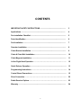
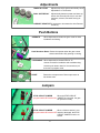
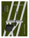
APOLLO
Gate Operators, Inc.
Model
7300
Model
7300ETL
Residential & Heavy Duty Commercial Slide Gate Operator
INSTALLATION MANUAL
04/07
CONTENTS
IMPORTANT SAFETY INSTRUCTIONS ..........................................................
3
Applications ....................................................................................................
4
Pre-Installation Checklist ................................................................................
5
Parts Identification ..........................................................................................
6
Pad Installation ................................................................................................
7
Operator Installation ........................................................................................
8
Chain Bracket Installation ...............................................................................
9
Chain & Chain Bolt Installation .......................................................................
10
Chain Magnets Installation ..............................................................................
11
Left or Right Hand Operation ……………………………………………………..
12
Quick Release Operation ..................................................................................
13
Programming Instructions …………………………………………………………. 14
Control Board Connections .............................................................................
15
Siren Connection …………………………………………………………………….
22
Radio Receiver Options …………………………………………………………….
23
Warranty ...........................................................................................................
24
2
IMPORTANT SAFETY INSTRUCTIONS
WARNING - To reduce the risk of injury or death:
•
•
•
•
•
•
READ AND FOLLOW ALL INSTRUCTIONS.
Installation should be performed by a professional installer.
Required welding should be performed by a qualified welder.
Should electricity be required, use a certified electrician only.
Any device that requires 120 Volts AC should be U.L. approved.
Review with the owner all safety concerns including:
⇒
⇒
⇒
⇒
⇒
⇒
⇒
•
•
•
•
•
•
•
•
Do not operate the gate unless area around gate is in full view.
Never let children operate or play with gate controls. Keep the remote control
away from children.
Always keep people and objects away from the gate. NO ONE SHOULD CROSS
THE PATH OF THE MOVING GATE.
Periodically test the obstruction sensitivity to assure safe and proper
operation. Do not test sensitivity by standing between the gate and the hinge or
stop post.
The “CAUTION AUTOMATIC GATE” signs should be clearly visible from both
sides of the gate.
Always insure that the gate has closed securely before leaving area.
Arrange with local fire and law enforcement for emergency access.
Use the emergency release only when the gate is not moving.
A secondary entrapment device such as loop detectors, edge switches, and beam
detectors are highly recommended and required to meet the UL325 standard.
Install control devices such as keypads far enough away (5 feet or further) from any
moving parts of the operator and gate to prevent possible injury.
Do not install control box where the gate can come in contact with person using the
push button on side of control box.
Always disconnect the battery or power source when making adjustments or repairs to
any part of the gate or operator.
All rollers should be covered to prevent injury.
KEEP GATES PROPERLY MAINTAINED. Read the owner’s manual. Have a qualified
service person make repairs to gate hardware.
The entrance is for vehicles only. Pedestrians must use separate entrance.
Test the gate operator monthly. The gate MUST reverse on contact with a rigid object or
stop when an object activates the non contact sensors. After adjusting the force or limit of
travel, retest the gate operator. Failure to adjust and retest the gate operator properly can
increase the risk of injury or death.
SAVE THESE INSTRUCTIONS.
3
APPLICATIONS
The Apollo Model 7300ETL Slide Gate Operator is designed to handle a slide gate
up to 32 feet in total length (30 foot gate with 3 foot tail) and 1,000 lbs. A professional
fence or gate dealer is recommended to assure proper installation. Apollo Gate
Operators are available only through qualified dealers with an outstanding reputation
in the fence and gate industry. These dealers will be able to recommend the proper
equipment for particular applications. Apollo Gate Operators are 12 Volt DC (Direct
Current) powered. A 12 Volt sealed battery (33 ampere hour minimum) is
recommended. There are several advantages with 12 Volt DC systems:
•
•
•
Low voltage virtually eliminates risk of electrical shock.
Battery powered operators provide up to 200 operations in the event of
power outages.
The battery may be recharged with a trickle charger or by solar energy
(Electrical battery chargers should have a class 2 transformer rating).
If a trickle charger is used and a standard electrical outlet is not readily available, a
licensed electrician will be required for proper electrical hook up.
The following table should be used as a guide for capacity of operation of operators
only, additional options may reduce the the daily usage. Please note that the charge
capability of solar panels will vary with different geographical locations. All solar panels and battery chargers are designed for use with a 12 volt battery.
Daily Cycles
1-10
5 watt solar panel
1-20 1-40
1-60
1-80
80+
*
10 watt solar panel
*
20 watt solar panel (requires 5310 regulator)
30 watt solar panel (requires 5310 regulator)
*
*
40 watt solar panel (requires 5310 regulator)
*
1.5 amp battery charger
*
10 amp battery charger
*
Note: Double the amount of solar panels for Dual Gate Operators.
4
PRE-INSTALLATION CHECKLIST
The following checklist should be used before beginning installation:
Verify that the proper operator has been selected for this application.
Verify proper installation and operation of the gate.
1. Are all rollers covered with a protective housing?
2. Are the rollers servicable?
3. Does the gate roll free and level?
4. Will the gate require a locking device?
5. Are the main posts sturdy enough to handle the gate & operator?
Determine the general location of the operator, chian brackets, and solar
panel (if used).
1. Is there a suitable location for the operator?
2.Can the solar panel (if used) be mounted in an unobstructed area facing
south?
3. Will additional solar panel cable be required?
4. Is electricity available (if required)?
Consider safety and access options. Recommend if needed.
1. Will there be chidren or animals in the area?
2. Are safety loops, edge switches, or photo beam detectors required?
3. How can the gate be opened in emergencies?
4. How will visitors enter and exit?
5. Will vehicles (and trailers) have sufficient room off roadway to operate any
control devices such as keypads?
5
PARTS IDENTIFICATION
Chain Brackets (2)
Operator
Chain Bolts with hardware (2 each)
Master Chain Links (2 each)
5/16 Washers, Lock
Nuts, & Nuts (8 each)
Magnetic Chain Limits
with hardware (2 each)
5/16 U Bolts (4 each)
Tie Wraps (4 each)
#40 Roller Chain (35 feet)
#201
5 Watt Solar Panel & Bracket
(optional)
#404C
Automatic Battery Charger (optional)
6
#273G
CAUTION Signs (2 each)
PAD INSTALLATION
Direction of Opening
5”
12”
24”
24”
Driveway
PadPad
Location
Location
Fig. A
Fig. B
Conduit requirements should be considered in the planning stage. If electrical power is required, a
separate conduit should be installed for electrical only. A certified electrician should be consulted for
the proper conduit material (Figure C & D).
14”
3”
5”
Fig. C
AREA FOR CONDUIT
ENTRY
Fig. D
7
OPERATOR INSTALLATION
Four 1/2” anchor bolts (not supplied) are
recommended to mount the chassis. The
holes should be drilled with a 1/2”
concrete drill bit.
STEP 1. Set the operator on the pad as shown. Align the sprockets 3 to 5 inches from the inside
surface of the gate.
STEP 2. Mark the four mounting holes on the pad.
STEP 3. Remove the operator and drill the holes according to the anchor bolt manufacturers instructions.
STEP 4. Replace the operator and fasten to the pad.
3”-5”
Chain path
(Make sure
the chain
path clears
all posts and
obstacles).
Mounting Holes
(4)
TOP VIEW
8
CHAIN BRACKET INSTALLATION
STEP 1. Assemble chain bracket with 5/16” U-bolt & hardware to each end of the gate as shown.
Do not tighten at this time.
STEP 2. Align the left chain
bracket slot with the top teeth
of the idler sprocket.
TIP: If welding equipment is
available, tack weld the chain
bracket to the gate on each
end to prevent slippage.
Idler Sprocket
Main Sprocket
STEP 3. Align the right
chain bracket slot with the
bottom teeth of the main
sprocket.
STEP 4. Tighten all hardware.
9
CHAIN & CHAIN BOLT INSTALLATION
STEP 1. Position the gate so that the operator is in the center of the
gate. Connect chain bolt to the chain bracket as shown on both ends of
the gate.
STEP 2. Attach the chain to the chain bolt using the master chain link. Do not
tighten the chain bolts .
Note: A chain breaking tool may
be required to reduce the chain to
the proper length.
10
CHAIN MAGNETS INSTALLATION
1. Align each magnet with the corresponding switch on the operator.
2. Connect the battery and adjust the magnets for proper open & close limits.
WARNING : Always disconnect battery prior to relocating the magnet.
Limit Switch
Magnet
TIP: If the gate automatically
opens after the close timer
expires, reverse the red &
black motor wires and reverse
the orange & white limit wires.
11
Left or Right Hand Operation
Apollo’s line of slide gate operators are pre-wired to open the gate to the right and close the gate to the
left (looking from the inside of the property).
If the operator is to be installed on the left side of the drive, use wiring diagram B
B
L
A
C
K
R
E
D
BB
LL
R AA R
E CC E
D KK D
R
E
D
O
R
A
N
G
E
B
L
A
C
K
G
R
E
E
N
B
L
A R
C E
K D
Factory Hookup
W
H
I
T
E
B
L
A
C
K
A
R
E
D
BB
LL
R AA R
E CC E
D KK D
W
H
I
T
E
B
Gate in closed position
Gate in closed position
operator
operator
12
G
R
E
E
N
O
R
A
N
G
E
QUICK RELEASE OPERATION
Engaged
Engaged
Pull & turn 1/2 inch to disengage
13
STEP 7
Programming Current Sensing
The 835/836 control boards incorporate a safety feature that will put the operator into a hard shutdown mode if the control board detects a current sense
two consecutive times during a cycle. This hard shutdown condition can only
be reset by shorting the FIREBOX or UL connectors on the left side of the
control board to ground. This condition may also be reset by pressing the
HARD SHUTDOWN RESET button located toward the upper right hand corner of the control board. If a firebox is used in the installation, The firebox
door (optional) should be opened and closed to reset the control board.
The following instructions must be followed at installation for proper safety assurance.
All limits should be set before beginning this procedure.
This new procedure applies to revision 31 or higher firmware.
1. Press and hold the LED ENABLE button for five seconds. The STOP LED will blink
indicating that the board is in learn mode.
3. Cycle gate for 3 full cycles. The STOP LED will stop blinking indicating that the board
is now ready for normal operation
4. Test the auto reverse sensitivity to ensure maximum safety protection. The current
sensitivity adjustment pot may be adjusted to decrease or increase sensitivity.
COUNTER CLOCKWISE
CLOCKWISE
More sensitivity
Less sensitivity
Gate is easy to current
sense
Gate is harder to
current sense
8. Refer to the 835/836 Operator Control Board Manual to set other options such as
program switch options and close timer adjustments.
Installation is now complete.
Note: Program switch #9 is no longer functional and the current sense may be readjusted
at any time.
14
APOLLO
Gate Operators, Inc.
835/836 Gate Control Board
Firmware Version 31 and up
Rev F
07/15/2005
15
PROGRAMMING INSTRUCTIONS
Once the operator is installed or if the control board is replaced, you will need to program
the control board for proper current sensing. The operator should be functional and the
open and close limits set.
1. Push and hold the LED ENABLE button for five seconds.
The “STOP” LED will blink indicating the board is in learn mode.
2. Cycle the gate three full times (must read open and close limit switches each cycle).
The “STOP” LED will now stay illuminated.
3. Adjust the current sensitivity pot to insure safe operation
The current sensitivity may be readjusted at any time without relearning the board.
Periodically check the current sensitivity for safe operation.
16
835/836 Control Board Parts Identification
Program Switches
Timer To Close Dual Gate Delay Current Sensitivity Adjustments
Microprocessor
GateLink Connector
Hard Shutdown Reset
Operate Push Button
Remote Monitor Outputs
and Photo Eye
Optional Device Inputs
LED Enable & Learn
Mode Push Button
Stop Circuit Jumper
Control Board Reset
Fire & ETL Inputs
Optional Device Input
Emergency Bypass
Actuator Connector
(Slave)
Reverse Battery Polarity
Indicators
17
Actuator Connector
(Master)
Actuator Connector
7
5
8
3
6
1
4
2
Board Actuator
Cable
Function
Pin 1
Pin 2
Pin 3
Pin 4
Pin 5
Pin 6
Pin 7
Pin 8
Open Limit
Close Limit
Motor (positive on open, negative on close)
Motor (negative on open, positive on close)
Common for both limit switches
Feedback from intelligent actuator(816E/816EX)
Battery Negative
Battery Positive
Orange
White
Black
Red
Green
Yellow
Black
Red
EMERGENCY BYPASS (open only)
Applies battery voltage directly to motor to open gate if
control board fails. User must unplug before gate opens
to maximum travel or 15 amp fuse will open. Fuse
should be checked before returning gate to service.
Remote Outputs and Photo Eye Hookup
12V
Supplied battery voltage
MAS
Master Operator Indicator (indicates master side of gate is closed)
+12V when on closed limit. Ground when off of closed limit.
Slave Operator Indicator (indicates slave side of gate is closed)
+12V when on closed limit. Ground when off of closed limit.
Battery supplied ground
SLV
GND
SIREN Connect to siren +
applies +12V when gate(s) are running, or in hard shutdown
GND
Battery supplied ground
LOCK
Connect to lock + (optional) Magnetic or Solenoid type locks (Dip Switch #6 Selectable)
Photo Eye Hookup
Photo eye / safety loop wiring. Connect the positive power wire of the accessory to
12V. Connect the ground wire of the accessory to MAS (upper right area of the
835/836 board). Connect the relay wires of the accessory as normal: COM to GND.
NO to SAFETY (#14) (for a safety device). When the gate operator begins opening
(comes off of the closed limits) the MAS terminal will become a ground and will
complete the flow of power to the accessory. This will power the accessory up and it
will work as normal until the gate gets closed and the MAS terminal switches and the
device will power down.
18
Adjustments
TIMER TO CLOSE
Adjusts time before gate automatically closes
Adjustable 5 to 70 seconds.
DUAL GATE DELAY
Adjusts delay between master and slave operation 0-4 seconds (836 only for use with
magnetic, solenoid, and other locking de
vices)
CURRENT SENSITIVITY Increases or decreases the Auto Reverse
sensitivity.
Push Buttons
OPERATE
When depressed, activates the gate. Used for initial
installation and testing.
Hard Shutdown Reset Resets the operator when the gate current
senses twice before fully opening or closing.
LED ENABLE When depressed, activates LEDs for 15
minutes to assist in installation and troubleshooting.
Hold the push button down for five seconds to put
the board in program mode.
RESET
Resets the microprocessor. Returns processor to
last known state.
Jumpers
STOP CIRCUIT JUMPER
When the STOP CIRCUIT
program switch #5 must be ON JUMPER is connected, the gate
will operate normally.
STOP CIRCUIT JUMPER
When a 3-button station is conprogram switch #5 must be OFF nected to the board, the STOP
CIRCUIT JUMPER must be removed.
19
Program Switches
OFF
ON
1 TIMER TO CLOSE
Gate does not automatically close.
Gate automatically closes.
2 TIMER TO CLOSE OPT.
Gate automatically closes from
any position after opening.
Gate automatically closes only when completely
open (open limit engaged).
3 SLAVE DISABLE
Enables slave side (dual gate use).
Disables slave side. (single gate use)
4 SIREN DELAY
Siren (optional) active when gate is
moving.
Siren (optional) starts 5 seconds before gate moves.
5 ‘STOP’ CIRCUIT ENABLE
Must hold down open or close
buttons to move gate. Gate stops
when button released.
Normal operation
Momentary open or close input runs gate to limit.
6 LOCK TYPE
For 12V mechanical (solenoid) locks.
(+12V for 4 seconds on open cycle)
For 12V magnetic locks.
(+12V when on close limit)
7 COAST ENABLE
Gate will stop immediately when at
Open or Close limit
Gate will coast (minimally) when it reaches limits.
Recommended for 7500 slide operator only.
8 FREE EXIT OPT.
A free exit input will open gate from
closed position or after a close cycle
only.
A free exit input will open gate from any
position after an open or close cycle.
9 DUAL GATE SYNC
Both gates operate at normal
Speed (slave slower than
Master).
This feature will control the master gate to open
or close at the same speed as the slave gate.
10 SMART ACT.
Off for 416E & 416EX actuators,
slide gates, 3500 or when slow down
feature is not desired.
Used for 816E & 816EX actuators only
(soft start & stop).
20
Optional Device Inputs
GND
Supplied Battery Ground
INP
Activate Gate (Push button activation when momentarily shorted to ground)
12V
Supplied Battery Voltage (Protected with 3 Amp fuse)
GND
Supplied Battery Ground
INP
Activate Gate (Push button activation when momentarily shorted to ground)
12V
Supplied Battery Voltage (Protected with 3 Amp fuse)
EDGE
Reverse edge input. When grounded, will stop and reverse gate if closing, resets close timer if gate is open.
EDGE
Reverse edge input. When grounded, will stop and reverse gate if closing, resets close timer if gate is open.
GND
Supplied Battery Ground
GND
Supplied Battery Ground
STOP
Stop input from a 3 button station (must remove STOP CIRCUIT JUMPER) Normally closed
CLOSE Close input from a 3 button station (see program switch #5 for options)
OPEN
Open input from a 3 button station (see program switch #5 for options)
GND
Supplied Battery Ground
GND
Supplied Battery Ground
FREE EXIT
GND
Supplied Battery Ground
SHADOW
GND
SAFETY
Opens gate if closed, stops and reverses gate if closing, resets close timer if gate is open.
Resets close timer when gate is open (also referred to as under gate loop)
Supplied Battery Ground
Resets close timer if gate is open, stops and reverses if gate is closing. (Does not open a closed gate)
GND
Supplied Battery Ground
FIRE
When grounded, opens gate and holds gate open until released.
Clears “Hard Shutdown” mode of software.
When grounded, opens gate and holds gate open until released.
Clears “Hard Shutdown” mode of software.
UL
GND
Supplied Battery Ground
INP
Activate Gate (Push button activation when momentarily shorted to ground)
12V
Supplied Battery Voltage (Protected with 3 Amp fuse)
21
APOLLO Gate Operators, Inc.
911 Siren
The 911 Siren is included with all Apollo ETL Gate Operators.
Mount siren in an area that will produce maximum performance (additional wire may be required).
Connect the red wire to the SIREN connector on the Remote Monitor Output Connector block.
Connect the black wire to the GND connector on the Remote Monitor Output Connector block.
Red
Black
Set Program Switch # 4 as preferred:
ON - Upon activation, Siren will start for 5 seconds before gate(s) begin moving.
OFF - Siren and gate(s) start immediately upon activation.
22
APOLLO
RECEIVER OPTIONS
Gate Operators
Do not confuse the receiver code switches with the red program switches on the gate control board.
Never set all code switches to the same position. Transmitters must match code switches for proper operation.
If power is taken directly from battery or connected as shown below, receiver should be configured for 12VDC
Multi-Code/Digi-Code
black
gray
gray
red
Allstar
white
black
red
Lift-Master*
1
2
3
4
Heddolf
black
white
yellow
red
Linear
white/silver
common
n/o
white/gold
* Lift-Master will require that the 12/24 jumper be set to 12 and the C/M (constant/momentary) jumper be set to C
23
APOLLO
Gate Operators, Inc.
LIMITED TWO-YEAR WARRANTY
Apollo Gate Operators are warranted against defects for a period of
24 months from the date of purchase, providing recommended installation
procedures are followed. This warranty is in lieu of all other warranties
expressed or implied (some states do not allow limitations on how long an
implied warranty lasts, so this limitation may not apply to you) and shall be
considered void if damage was due to improper installation or use,
connection to improper power source, or if damage was caused by fire,
flood, or lightning. The manufacturer will not be responsible for any labor
charges incurred in the removal or replacement of defective parts.
In case of failure due to defective material or workmanship during the
warranty period, the defective part will be repaired or replaced at the
manufacturer’s option at no charge if returned freight prepaid. New or factory
rebuilt replacements may be used. Replacement parts are warranted for the
remaining portion of the original warranty period. The manufacturer will pay
standard ground freight on the return of repaired or replaced items in
warranty.
24