1
UGP 712 Manual_Layout 1 2/5/2014 4:56 PM Page 1
UGP712
UGP 712 Manual_Layout 1 2/5/2014 4:56 PM Page 2
UGP 712 Manual_Layout 1 2/5/2014 4:56 PM Page 3
Installation Instructions & Safety Information Manual
TA BLE OF CONTENTS
Gate Operator Class Categories & Example ....................................................4
Protection Against Entrapment
....................................................6
Use & Application
.................................................7-8
Important Safety Instructions
....................................................9
Maintenance Instructions
....................................................10
Intended Use
....................................................7
Types of Installations
..............................................11-12
Limit Switch Set Up
...................................................13
Control Box
..................................................14
Electrical
..................................................15
Primary/Secondary Connections
..................................................16
Warning Placards
Loop Rack
..................................................17
Accessory Connections
.............................................18-21
Selectable Features
.............................................22-23
Solar Installation
.................................................24
Parts Diagram
..................................................25
TECHNICAL SUPPORT: (909) 259-6001
UGP712
3
UGP 712 Manual_Layout 1 2/5/2014 4:56 PM Page 4
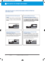
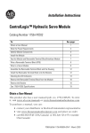
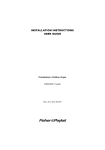
Gate operator class categories and examples
READ AND FOLLOW ALL INSTRUCTIONS MANUAL BEFORE ATTEMPTING
ANY INSTALLATION
Residential Vehicular Gate Operator
Class I
Commercial/General Access
Vehicular Gate Operator Class II
A vehicular gate operator (or system) intended
for use in a home of one-to four single family
dwelling, or a garage or parking area associated
therewith.
A vehicular gate operator (or system) intended
for use in a commercial location or building such
family units), hotel, garages, retail store, or other
building servicing the general public.
HOTEL
Industrial/Limited Access Vehicular
Gate Operator Class III
Restricted Access Vehicular Gate
Operator Class IV
A vehicular gate operator (or system) intended for
use in an industrial location or building such as
a factory or loading dock area or other locations
not intended to service the general public.
A vehicular gate operator (or system) intended
for use in a guarded industrial location or building
such as an airport security area or other restricted
access locations not servicing the general public,
in which unauthorized access is prevented via
supervision by security personnel.
FACTORY
HANGAR 00
DOCK
4
UGP712
TECHNICAL SUPPORT: (909) 259-6001
UGP 712 Manual_Layout 1 2/5/2014 4:56 PM Page 5
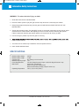
Information Safety Instructions
WARNING – To reduce the risk of injury or death:
1. READ AND FOLLOW ALL INSTRUCTIONS.
2. Never let children operate or play with gate controls. Keep the remote control away from children.
3. Always keep people and objects away from the gate. NO ONE SHOULD CROSS THE PATH OF THE
MOVING GATE.
4. Test the gate operator monthly. The gate MUST reverse on contact with a rigid object or stop when an object
activates the non-contact sensors. After adjusting the force or the limit of travel, retest the gate operator.
Failure to adjust and retest the gate operator properly can increase the risk of injury or death.
5. Use the emergency release only when the gate is not moving.
repairs to gate hardware.
7. The entrance is for vehicles only. Pedestrians must use separate entrance.
8. SAVE THESE INSTRUCTIONS
SPECIFICATIONS
Maximum Gate Weight:
Maximum Gate Length:
Opening Time:
Maximum Opening Angle:
Power Requirements:
Main Power:
Operating Temperature:
700 lbs.
12 feet
90° opening in 16-21 seconds
110°
120 VAC Single Phase at 2 Amps or 220 VAC Single Phase at 1 Amp
Power Input: 100-240 VAC
Select 115 /230 VAC Single Phase
Built-in 24VDC battery backup (7AmpHr 12VDC x 2)
-20°C (-4°F) to 70°C (158°F)
TECHNICAL SUPPORT: (909) 259-6001
UGP712
5
UGP 712 Manual_Layout 1 2/5/2014 4:56 PM Page 6
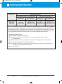
PROTECTION AGAINST ENTRAPMENT
Usage Class
Gate Operator Category
Horizontal Slide, Vertical lift, and Vertical Pivot
Vehicular I and II
Vehicular III
Vehicular IV
Swing and Vertical Barrier (arm)
Primary Type*
Secondary Type*
Primary Type*
Secondary Type*
A
A, B1, or B2
A, B1, B2, or D
B1, B2, or D
A, B1, B2, D, or E
A, B1, B2, D, or E
A, or C
A, B1, B2, or C
A, B1, B2, C, or D
B1, B2, C, or D
A, B1, B2, C, D, or E
A, B1, B2, C, D, or E
Note - The same type of device shall not be utilized for both the primary and the secondary entrapment
protection means. Use of a single device to cover both the opening and closing directions is in accordance with
the requirement; however, a single device is not required to cover both directions. A combination of one Type
B1 for one direction and one Type B2 for the other direction is the equivalent of one device for the purpose of
complying with the requirements of either the primary or secondary entrapment protection areas.
a
Entrapment protection Types:
Type A: Inherent entrapment protection system.
Type B1: Provision for connection of, supplied with, a non-contact sensor (photoelectric sensor
or the equivalent).
Type B2: Provision for connection of, or supplied with, a contact sensor (edge device or the equivalent)
Type C: Inherent adjustable clutch or pressure relief device.
Type D: Provision for connection of, or supplied with, an actuating device requiring continuous pressure to
maintain opening or closing motion of the gate.
Type E: An audio alarm.
6
UGP712
TECHNICAL SUPPORT: (909) 259-6001
UGP 712 Manual_Layout 1 2/5/2014 4:56 PM Page 7
Use and Application
The model is intended for Class I and Class II (Residential/Light Commercial) up to
10 units usage on a vehicular swing gate application.
a) Install the gate operator only when:
1) The operator is appropriate for the construction of the gate and the usage Class of the gate,
2) All exposed pinch points are eliminated or guarded.
b) The operator is intended for installation only on gates used for vehicles. Pedestrians must be supplied with a
separate access opening. The pedestrian access opening shall be designed to promote pedestrian usage. Locate the gate such that persons will not come in contact with the vehicular gate during the entire path of travel
of the vehicular gate.
c) The gate must be installed in a location so that enough clearance is supplied between the gate and adjacent
structures when opening and closing to reduce the risk of entrapment. Swinging gates shall not open into
public access areas.
d) The gate must be properly installed and work freely in both directions prior to the installation of the gate operator. Do not over-tighten the operator clutch or pressure relief valve to compensate for a damaged gate.
e) For gate operators utilizing Type D protection:
1) The gate operator controls must be placed so that the user has full view of the gate area when the gate is
moving,
2
The placard equivalent to the following: “To reduce the risk of electric shock the operator power is to be
provided from a weatherproof outlet in the case of attachment plug connection or weatherproof junction
box in the case of permanent wiring according to the National Electrical Code, NFPA 70.” shall be placed
adjacent to the controls,
3) An automatic closing device (such as a timer, loop sensor, or similar device) shall not be employed, and
4) No other activation device shall be connected.
f)
Controls intended for user activation must be located at least six feet (6’) away from any moving part of the
gate and where the user is prevented from reaching over, under, around or through the gate to operate the
controls. Outdoor or easily accessible controls shall have a security feature to prevent unauthorized use.
g) The Stop and/or Reset button must be located in the line-of-sight of the gate. Activation of the reset control
shall not cause the operator to start.
h) A minimum of two (2) WARNING SIGNS shall be installed, one on each side of the gate where easily visible.
TECHNICAL SUPPORT: (909) 259-6001
UGP712
7
UGP 712 Manual_Layout 1 2/5/2014 4:56 PM Page 8
Use and Application
tion:
i)
For gate operators utilizing a non-contact sensor:
1) See instructions on the placement of non-contact sensors for each Type of application,
2) Care shall be exercised to reduce the risk of nuisance tripping, such as when a vehicle, trips the sensor
while the gate is still moving, and
3) One or more non-contact sensors shall be located where the risk of entrapment or obstruction exists,
such as the perimeter reachable by a moving gate or barrier.
j)
For a gate operator utilizing a contact sensor:
1) One or more contact sensors shall be located where the risk of entrapment or obstruction exists, such as
at the leading edge, trailing edge, and post mounted both inside and outside of a vehicular horizontal slide
gate.
2) One or more contact sensors shall be located at the bottom edge of a vehicular vertical lift gate.
3) One or more contact sensors shall be located at the pinch point of a vehicular vertical pivot gate.
4) A hardwired contact sensor shall be located and its wiring arranged so that the communication between
the sensor and the gate operator is not subjected to mechanical damage.
5) A wireless device such as one that transmits radio frequency (RF) signals to the gate operator for entrapment protection functions shall be located where the transmission of the signals are not obstructed or
impeded by building structures, natural landscaping or similar obstruction. A wireless device shall function
under the intended end-use conditions.
6) One or more contact sensors shall be located on the inside and outside leading edge of a swing gate.
Additionally, if the bottom edge of a swing gate is greater than 6 inches (152 mm) above the ground at any
point in its arc of travel, one or more contact sensors shall be located on the bottom edge.
7) One or more contact sensors shall be located at the bottom edge of a vertical barrier (arm).
8
UGP712
TECHNICAL SUPPORT: (909) 259-6001
UGP 712 Manual_Layout 1 2/5/2014 4:56 PM Page 9
Important Safety Instructions
WARNING – To reduce the risk of injury or death:
1. READ AND FOLLOW ALL INSTRUCTIONS.
2. Never let children operate or play with gate controls. Keep the remote control away from children.
3. Always keep people and objects away from the gate. NO ONE SHOULD CROSS THE PATH OF THE
MOVING GATE.
4. Test the gate operator monthly. The gate MUST reverse on contact with a rigid object or stop when an object
activates the non-contact sensors. After adjusting the force or the limit of travel, retest the gate operator.
Failure to adjust and retest the gate operator properly can increase the risk of injury or death.
5. Use the emergency release only when the gate is not moving.
.((3*$7(63523(5/<0$,17$,1('5HDGWKHRZQHU¶VPDQXDO+DYHDTXDOL¿HGVHUYLFHSHUVRQPDNH
repairs to gate hardware.
7. The entrance is for vehicles only. Pedestrians must use separate entrance.
8. SAVE THESE INSTRUCTIONS
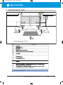
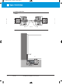
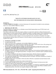
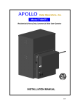
Overall Dimensions
Important Safety Instructions
1.375" Electrical hole
Drain Opening
2.24"
16.61"
Approx .
0.59"
6.61"
9.375"
9.3/8"
Top View
Side View
TECHNICAL SUPPORT: (909) 259-6001
UGP712
9
UGP 712 Manual_Layout 1 2/5/2014 4:56 PM Page 10
Maintenance Instructions
Maintenance instructions of UGP 712 performed by a qualified gate operator technician
Installation, all connections, programming, repair and modifications must be done by a
qualified professional
gate operator
installer.
services need
to be
periodically
performed:
The following
• Check and adjust the gate operator for force, speed, and sensitivity.
• Make sure all power (AC/DC ) connections are corrosion free.
• Check all batteries for proper voltage of the intended use. A fully charged battery must be 26
VDC minimum.
&KHFNWKHLQFRPLQJOLQHYROWDJHDQGFRQ¿UPLWLVZLWKLQRILWVUDWLQJRUYROWV
• Verify battery backup functionally by turning off the power source (115 VAC and 230 VAC).
Don’t forget to restore power after testing.
• Check gate hinges and operator/arm mounting brackets and lubricate them with heavy-duty,
high-performance lubricant and avoid spillage.
• Test (use caution) all contact and non-contact sensors, all vehicle detectors, keypad, telephone
entry system or other control devices applicable.
• Test the manual release feature on the operator/arm.
Maintenance instructions of UGP 712 performed by the end user/home owner
,QVWDOODWLRQDOOFRQQHFWLRQVSURJUDPPLQJUHSDLUDQGPRGL¿FDWLRQVPXVWEHGRQHE\DTXDOL¿HGSURIHVVLRQDO
JDWHRSHUDWRULQVWDOOHU(QGXVHUVKRPHRZQHUVPXVWFDOODTXDOL¿HGSURIHVVLRQDOJDWHRSHUDWRULQVWDOOHUIRU
SURJUDPPLQJFKDQJHVUHSDLUVDQGPRGL¿FDWLRQV
Although all Platinum Access Systems’ gate operators are virtually maintenance free to an end user/home owner
minimal maintenance is recommended to ensure a smooth operation of this unit.
End users/home owners:
10
•
Perform maintenance every six months, or when strenuous noise from gate hinges and/or opera
tor/arm mounting brackets is detected. Lubricate them with heavy-duty, high-performance lubricant
and avoid spillage.
•
DO NOT take the cover off the operator/arm and/or the electrical control box to perform maintenance.
•
Make sure there are no cars in the path of the gate while performing maintenance.
•
Make sure the person performing maintenance is the only person in control of all control devices
in order to avoid possible involuntary activation of the gate operator.
•
Keep spraying water hoses and sprinkler systems away from the gate, gate operator/arm and the
electrical control box at all times. Keep that general area as clean as humanly possible.
•
Test (use caution) all non-contact sensors, all vehicle detectors, keypad, telephone entry system or
other control devices applicable.
UGP712
TECHNICAL SUPPORT: (909) 259-6001
UGP 712 Manual_Layout 1 2/5/2014 4:56 PM Page 11
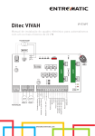
Types of Installations
4.
STANDARD INSTALLATION
2
3
5
4x0.5 mm²
RX - 4x0.5 mm²
TX - 4x0.5 mm²
7
7
6
3x1.5 mm²
2x1.5 mm²
6
*
*
7
7
A
TX - 4x0.5 mm²
RX - 4x0.5 mm²
4
1
* 3x0,75 mm² + 1x1,5 mm² [CUBIC6]
2x1,5 mm² [CUBIC6H]
R
Ref.
1
2
Description
115
7
i
NOTE: the given operating and performance features can only be guaranteed with the use of DITEC
accessories and safety devices.
TECHNICAL SUPPORT: (909) 259-6001
UGP712
11
UGP 712 Manual_Layout 1 2/5/2014 4:56 PM Page 12
Types of Installations
5.
Examples applications
UGP712
max 110°
2 5/8”
3”
8”
Concrete
Soil Drainage
12
UGP712
TECHNICAL SUPPORT: (909) 259-6001
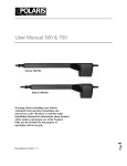
UGP 712 Manual_Layout 1 2/5/2014 4:56 PM Page 13
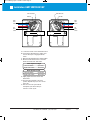
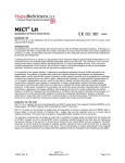
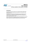
Installation: LIMIT SWITCH SET-UP
Limit Switch Cam
Limit Switch Cam
Limit Disc
Limit Disc
Right
Limit
Switch
Right
Limit
Switch
Drive
Arm
Drive
Arm
Left
Limit
Switch
Left
Limit
Switch
A. Loosen the screws on the Limit Switch Cams.
B. Remount the articulated arm, making sure
the cam wheel pin is engaged with the
clutch.
C. Move the gate manually to the closed position.
D. Move the Limit Switch Cams on the Cam
Wheel to actuate each limit switch.
Gate Opens to Right
Left Limit Switch
Open limit
Right Limit Switch
Close limit
Gate Opens to Left
Left Limit Switch
Close limit
Right Limit Switch
Open limit
E. Slightly tighten the screw on the Limit
Switch Cam.
F. Move the gate manually to the open
position. Repeat steps a, b and c for the
other cam.
G. Run the unit 2 full cycles without
interruption (from limit to limit) to
execute a “Learn Cycle.”
TECHNICAL SUPPORT: (909) 259-6001
UGP712
13
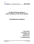
UGP 712 Manual_Layout 1 2/5/2014 4:56 PM Page 14
I
Installation: Control Box
The control box MUST be mounted within
5 feet of the gate operator. Mount the
control box as high as possible for best radio
reception. Make sure the control box is level.
The control unit weight is approximately
28 lbs. with supplied batteries.
1.
Remove the screws and open the control
box.
14.5"
2.
Disconnect the connector from the Main
Board.
15.5"
3.
Position the control box into the desired
place and mark the mounting holes.
4.
Depth: 6.5"
Select the mounting holes and remove the
knockouts using a screwdriver and hammer.
5.
Secure the control box to mounting surface.
Mounting Fastener
(not supplied)
Sealed Washer
(not supplied)
Control Box
Mounting Surface
14
UGP712
TECHNICAL SUPPORT: (909) 259-6001
UGP 712 Manual_Layout 1 2/5/2014 4:56 PM Page 15
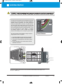
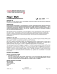
Installation: ElecTrical
power cable to the board. USE MIN. 14 AWG WIRE. FOLLOW ALL LOCAL ELECTRICAL CODES.
Black
To help protect the equipment from lightning and power
surges and to protect persons from shock hazard the
Operator must be grounded. The earth ground rod
must be located within 3 feet from the gate operator.
Use the proper type earth ground rod for your local
area. The ground wire must be a single, whole piece of
wire. Never splice two wires for the ground wire. If you
cut the ground wire too short, break it, or destroy
its integrity, replace it with a single wire length.
Prevent unnecessary turns or loops in ground wires.
The gate operator and the battery charger require a
single phase AC line to operate.
Green
Red
White
Power Harness
1. Turn off the breaker for the circuit you are using.
2. Select the proper voltage on the power board.
3. Connect the incoming power wires to the proper
terminals.
4. Turn on the breaker and check that AC ON and
CHARGE LED are lit.
To Power Harness
+ (White)
- (Green)
Earth Ground
Ground Rod
Earth Ground (Green/Yellow)
Neutral (White)
Hot (Black)
The power receptacle has been left unconnected till the installer decides what voltage to use.
Connect to 120VAC only
TECHNICAL SUPPORT: (909) 259-6001
UGP712
15
UGP 712 Manual_Layout 1 2/5/2014 4:56 PM Page 16
Installation: Primary/Secondary Connections
The control board provides a connector for the secondary actuator unit and automatically synchronizes
the secondary unit with the primary unit.
Outside
White Lg.
Black Sm.
Red Sm.
White Sm.
Red Lg.
Green Sm.
Black Lg.
Inside
White Lg.
Red Sm.
Black Sm.
White Sm.
Red Lg.
Green Sm.
Primary Unit
Black Lg.
Secondary Unit
Simply connect the Secondary arm to its applicable position, IN for open inside or OUT for open outside.
16
UGP712
TECHNICAL SUPPORT: (909) 259-6001
UGP 712 Manual_Layout 1 2/5/2014 4:56 PM Page 17
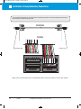
Installation: Loop Rack
Loop Rack (#GOC-LDR)
Safety
Gnd
Exit
Gnd
Center
Gnd
28V
Gnd
Center
Outside
Twist Wire Outside the
Loop 6 Twists/Foot
Until Its Connection
to the Loop Rack
Exit
Outside Safety
Loop
Safety
Safety
Center
Loop
Exit
Center
Inside Safety
Loop
Exit
Loop
Control Board
Connector
Inside
Loop Connector
TECHNICAL SUPPORT: (909) 259-6001
UGP712
17
UGP 712 Manual_Layout 1 2/5/2014 4:56 PM Page 18
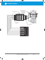
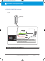
Installation: Accessory Connections
ACCESSORY CONNECTIONS:
To decrease the possibility of vehicle entrapment on the gate, vehicle loop detectors
need to be installed. The edge sensor and the photo-electric beam can be used for
secondary entrapment protection on every installation to prevent pedestrian or
animal entrapment. These accessories must be UL325 compliant devices.
Open
Commands
Safety Connections
Photo
Beam
Edge Sensor
Keypad
Fire
Override
TX
Center
Loop
Detector
Safety
Loop
Detector
Reopen Photo Beam
Note: Installing the photo beam in this way,
allows the gate to re-open all the way upon
obstruction of the photo-beam.
TX
Photo
Beam
The optional PBD connector provides a
controlled power supply for Photo Beam.
The power will be turned off when gate is
in close position to save battery.
Outside
Inside
18
UGP712
TECHNICAL SUPPORT: (909) 259-6001
Option for
Solar Power
Input ONLY
UGP 712 Manual_Layout 1 2/5/2014 4:56 PM Page 19
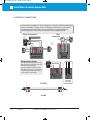
Installation: Accessory Connections
ACCESSORY CONNECTIONS (continued):
Radio Receiver
Need to verify the proper connections before connecting the Radio Receiver.
The maximum voltage that the control board / battery can provide is about 28V
for external accessories. If there is an electrical shot in the power to the
accessories, the control board will protect itself by shutting down and will
remain shut down until the short is fixed.
Two modes of operation that a radio receiver
can control the gate:
MS-109950
Receiver
Open-Close
By having the radio receiver connected as
illustrated and with the Timer OFF:
Every command of the radio transmitter
will control the gate as follow:
A. First command opens the gate
B. Second command CLOSE the gate if at
open position
C. Third command OPEN the gate
D. Any subsequent commands will continue
in the same order to control the gate.
This type of configuration is not recommended for a commercial installations.
RED
GRAY
GRAY
BLACK
Open Only
By having the radio receiver connected as
illustrated and with the Timer ON:
Each command of the radio transmitter is
ALWAYS AN OPEN COMMAND to the gate.
Linear MS-109950
Installation Diagram
TECHNICAL SUPPORT: (909) 259-6001
UGP712
19
UGP 712 Manual_Layout 1 2/5/2014 4:56 PM Page 20
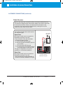
Installation: Accessory Connections
ACCESSORY CONNECTIONS (continued):
Solenoid Connection
The solenoid power connection must be
provided an external power source. This will
prevent damage to the battery in the event of
a line power failure.
Guard Station
This will control the gate operator to Open,
Stop, and Close the gate. The switches for
Open and Close must be normally open
type. The switch for Stop must be normally
close type. They all can be using the same
common ground. The control switch box
should be within sight of the gate, out of
reach of children, and away from moving
parts of the gate.
If no guard station or STOP switch is
installed, a jumper must be inserted between
“STOP(NC)” and “GND” pins.
20
UGP712
TECHNICAL SUPPORT: (909) 259-6001
OPEN
CLOSE
STOP
GND
OPEN
CLOSE
STOP
UGP 712 Manual_Layout 1 2/5/2014 4:56 PM Page 21
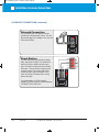
Installation: Accessory Connections
ACCESSORY CONNECTIONS (continued):
Locks
Magnetic Lock
(#PA-MAG13)
(Supplied with Lock Kit)
(Supplied with
Lock Kit)
Green
Black
White
24VDC
Red
The Magnetic Lock power connection must be provided an
external power source. This will prevent damaging the battery
in the event of line power failure.
OPTIONAL ACCESSORY- part # (PA-MAG13).
TECHNICAL SUPPORT: (909) 259-6001
UGP712
21
UGP 712 Manual_Layout 1 2/5/2014 4:56 PM Page 22
Installation: Selectable Features
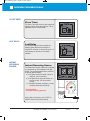
ADVANCING LOCK SELECT:
ADV MLOK
To set the maglock to be engaged before the
gate reaches the close or open position:
Select the DIP switch to ADV MLOK position.
OPEN ON POWER FAIL:
The Auto-Open feature in Platinum Access Systems Gate Operators enables the following
functionality in the event of power failure:
a. Open the gate in case of power failure (120 or 220 VAC).
b. Keep the gate at the open position as long as the there is no power.
c. Resume to normal operation when the power has been restored.
All accessories and safety devices are functional. The only function disabled is the close command.
Auto-Open
To enable the Auto-Open feature: Select the
DIP switch to AUTO OP position.
22
UGP712
TECHNICAL SUPPORT: (909) 259-6001
UGP 712 Manual_Layout 1 2/5/2014 4:56 PM Page 23
Installation: Selectable Features
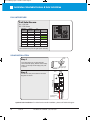
CLOSE TIMER:
Close Timer
The Close Timer will close the gate a set time
after the vehicle clears the gate area. This is
adjustable from 3 to 60 seconds.
LEAF DELAY:
Leaf Delay
An Overlap Delay has been provided for
biparting gates that have an emblem or
maglock for example. It will provide up to a 3
second delay on primary or secondary
operator.
INSTANT
REVERSING
SENSOR:
Instant Reversing Sensor
The Obstruction Sensor needs to be adjusted
to compensate for the installation and gate
weight. The overload adjustment is provided
to set the gate sensitivity.
a) If the gate reverses by itself or stops in
midcycle, it is too sensitive.
b) If the gate hits an object and does not
reverse or stop, it is not sensitive
enough.
c) Clockwise increases sensitivity, counterclockwise decreases sensitivity.
Test and adjust
for proper reversing pressure
(Note: When unit alarms, push “STOP” or
“RESET” button will clear the alarm)
TECHNICAL SUPPORT: (909) 259-6001
UGP712
23
UGP 712 Manual_Layout 1 2/5/2014 4:56 PM Page 24
Installation: Selectable Features & Solar Installation
FAIL SAFE/SECURE:
Fail Safe/Secure
On = Fail Safe
Off = Fail Secure
Fail/Safety
Battery
AC
(Input)
ON
Detection
Normal
Detection
Normal
Secure
ON
Normal
OFF
Fail Safe
ON
ON
Low/OFF
Low/OFF
Normal
OFF
Fail Safe
Fail Safe
OFF
OFF
Normal
Normal
Normal
OFF
Secure
Fail Secure
OFF
Low/OFF
Normal
Fail Secure
OFF
Low/OFF
OFF
Fail Secure
Output
Note: When the output is "Fail Safe", there is
less resistance to push the gate open manually.
SOLAR INSTALLATION:
12 VDC
Panels
Step 1
24 VDC
Panel
A 24V solar panel or two 12V solar panels with
minimum 80 watts capacity, Maximum Power Voltage
(VPM) > 31V and Open Circuit Voltage (VOC) >38V
is required.
+
–
+
–
Connect To Solar
Regulator Input
From Solar
Panel
Step 2
Connect the solar panel cables to the Solar
Regulator as shown.
BLACK
RED
GOC-REG24V-A
To Power Supply
(Pre-wired)
Optional Solar Installation: For Solar Panel controller installation, please call Technical Support.
24
UGP712
TECHNICAL SUPPORT: (909) 259-6001
UGP 712 Manual_Layout 1 2/5/2014 4:56 PM Page 25
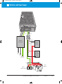
Batteries and Power Supply
- (Green)
+ (White)
- +
White
Outlet &
Receptacle
White
Reset
Switch
Red
Red
Red
+
Black
Hot
(Black)
Neutral
(White)
Solar
Regulator
“Out”
Earth Ground
(Green/Yellow)
Green
+
Black
Red
Power
Harness Plug
TECHNICAL SUPPORT: (909) 259-6001
+
24V
Batteries
UGP712
25
UGP 712 Manual_Layout 1 2/5/2014 4:56 PM Page 26
UGP 712 Manual_Layout 1 2/5/2014 4:56 PM Page 27
UGP 712 Manual_Layout 1 2/5/2014 4:56 PM Page 28
PLATINUM ACCESS SYSTEMS™
1725 E. Grevillea Court, Ontario, CA 91761
Phone: (855) 466-8686 I Fax: (909) 923-7890
www.PlatinumASI.com
© 2013 Platinum Access Systems, Inc. All Rights Reserved.